EP0991840B1 - Türantrieb - Google Patents
Türantrieb Download PDFInfo
- Publication number
- EP0991840B1 EP0991840B1 EP98942460A EP98942460A EP0991840B1 EP 0991840 B1 EP0991840 B1 EP 0991840B1 EP 98942460 A EP98942460 A EP 98942460A EP 98942460 A EP98942460 A EP 98942460A EP 0991840 B1 EP0991840 B1 EP 0991840B1
- Authority
- EP
- European Patent Office
- Prior art keywords
- door
- actuating
- fuse
- fastening
- fire
- Prior art date
- Legal status (The legal status is an assumption and is not a legal conclusion. Google has not performed a legal analysis and makes no representation as to the accuracy of the status listed.)
- Expired - Lifetime
Links
- 239000002184 metal Substances 0.000 claims abstract description 22
- 229910052751 metal Inorganic materials 0.000 claims abstract description 22
- 239000000463 material Substances 0.000 claims abstract description 16
- 239000000155 melt Substances 0.000 claims description 17
- 238000002844 melting Methods 0.000 claims description 17
- 230000008018 melting Effects 0.000 claims description 14
- 238000013016 damping Methods 0.000 claims description 7
- 239000004020 conductor Substances 0.000 claims description 4
- 230000009970 fire resistant effect Effects 0.000 claims 1
- 150000002739 metals Chemical class 0.000 abstract 1
- 239000010720 hydraulic oil Substances 0.000 description 6
- 239000003921 oil Substances 0.000 description 6
- 230000005540 biological transmission Effects 0.000 description 3
- 238000010438 heat treatment Methods 0.000 description 3
- 239000011810 insulating material Substances 0.000 description 3
- 238000000034 method Methods 0.000 description 3
- RYGMFSIKBFXOCR-UHFFFAOYSA-N Copper Chemical compound [Cu] RYGMFSIKBFXOCR-UHFFFAOYSA-N 0.000 description 2
- 229910000831 Steel Inorganic materials 0.000 description 2
- 230000009172 bursting Effects 0.000 description 2
- 229910052802 copper Inorganic materials 0.000 description 2
- 239000010949 copper Substances 0.000 description 2
- 230000003111 delayed effect Effects 0.000 description 2
- 238000004146 energy storage Methods 0.000 description 2
- 239000010959 steel Substances 0.000 description 2
- 238000010792 warming Methods 0.000 description 2
- 101100000858 Caenorhabditis elegans act-3 gene Proteins 0.000 description 1
- HEFNNWSXXWATRW-UHFFFAOYSA-N Ibuprofen Chemical compound CC(C)CC1=CC=C(C(C)C(O)=O)C=C1 HEFNNWSXXWATRW-UHFFFAOYSA-N 0.000 description 1
- 239000010425 asbestos Substances 0.000 description 1
- 239000000919 ceramic Substances 0.000 description 1
- 239000002131 composite material Substances 0.000 description 1
- 230000008878 coupling Effects 0.000 description 1
- 238000010168 coupling process Methods 0.000 description 1
- 238000005859 coupling reaction Methods 0.000 description 1
- 230000000694 effects Effects 0.000 description 1
- 239000012530 fluid Substances 0.000 description 1
- 239000011521 glass Substances 0.000 description 1
- 230000020169 heat generation Effects 0.000 description 1
- 238000009413 insulation Methods 0.000 description 1
- 238000004519 manufacturing process Methods 0.000 description 1
- 239000000203 mixture Substances 0.000 description 1
- 230000004048 modification Effects 0.000 description 1
- 238000012986 modification Methods 0.000 description 1
- 229920000642 polymer Polymers 0.000 description 1
- 230000000284 resting effect Effects 0.000 description 1
- 238000009420 retrofitting Methods 0.000 description 1
- 229910052895 riebeckite Inorganic materials 0.000 description 1
- 238000003892 spreading Methods 0.000 description 1
Images

Classifications
-
- E—FIXED CONSTRUCTIONS
- E05—LOCKS; KEYS; WINDOW OR DOOR FITTINGS; SAFES
- E05B—LOCKS; ACCESSORIES THEREFOR; HANDCUFFS
- E05B65/00—Locks or fastenings for special use
- E05B65/10—Locks or fastenings for special use for panic or emergency doors
- E05B65/104—Locks or fastenings for special use for panic or emergency doors actuated in response to heat, e.g. with fusible element, bimetal, memory shape or swelling material
-
- E—FIXED CONSTRUCTIONS
- E05—LOCKS; KEYS; WINDOW OR DOOR FITTINGS; SAFES
- E05F—DEVICES FOR MOVING WINGS INTO OPEN OR CLOSED POSITION; CHECKS FOR WINGS; WING FITTINGS NOT OTHERWISE PROVIDED FOR, CONCERNED WITH THE FUNCTIONING OF THE WING
- E05F3/00—Closers or openers with braking devices, e.g. checks; Construction of pneumatic or liquid braking devices
- E05F3/22—Additional arrangements for closers, e.g. for holding the wing in opened or other position
- E05F3/227—Additional arrangements for closers, e.g. for holding the wing in opened or other position mounted at the top of wings, e.g. details related to closer housings, covers, end caps or rails therefor
-
- E—FIXED CONSTRUCTIONS
- E05—LOCKS; KEYS; WINDOW OR DOOR FITTINGS; SAFES
- E05F—DEVICES FOR MOVING WINGS INTO OPEN OR CLOSED POSITION; CHECKS FOR WINGS; WING FITTINGS NOT OTHERWISE PROVIDED FOR, CONCERNED WITH THE FUNCTIONING OF THE WING
- E05F3/00—Closers or openers with braking devices, e.g. checks; Construction of pneumatic or liquid braking devices
- E05F3/22—Additional arrangements for closers, e.g. for holding the wing in opened or other position
- E05F2003/228—Arrangements where the end of the closer arm is sliding in a track
-
- E—FIXED CONSTRUCTIONS
- E05—LOCKS; KEYS; WINDOW OR DOOR FITTINGS; SAFES
- E05Y—INDEXING SCHEME ASSOCIATED WITH SUBCLASSES E05D AND E05F, RELATING TO CONSTRUCTION ELEMENTS, ELECTRIC CONTROL, POWER SUPPLY, POWER SIGNAL OR TRANSMISSION, USER INTERFACES, MOUNTING OR COUPLING, DETAILS, ACCESSORIES, AUXILIARY OPERATIONS NOT OTHERWISE PROVIDED FOR, APPLICATION THEREOF
- E05Y2800/00—Details, accessories and auxiliary operations not otherwise provided for
- E05Y2800/40—Physical or chemical protection
- E05Y2800/414—Physical or chemical protection against high or low temperatures
- E05Y2800/416—Physical or chemical protection against high or low temperatures against fire
-
- E—FIXED CONSTRUCTIONS
- E05—LOCKS; KEYS; WINDOW OR DOOR FITTINGS; SAFES
- E05Y—INDEXING SCHEME ASSOCIATED WITH SUBCLASSES E05D AND E05F, RELATING TO CONSTRUCTION ELEMENTS, ELECTRIC CONTROL, POWER SUPPLY, POWER SIGNAL OR TRANSMISSION, USER INTERFACES, MOUNTING OR COUPLING, DETAILS, ACCESSORIES, AUXILIARY OPERATIONS NOT OTHERWISE PROVIDED FOR, APPLICATION THEREOF
- E05Y2900/00—Application of doors, windows, wings or fittings thereof
- E05Y2900/10—Application of doors, windows, wings or fittings thereof for buildings or parts thereof
- E05Y2900/13—Type of wing
- E05Y2900/132—Doors
- E05Y2900/134—Fire doors
Definitions
- the invention relates to a door drive with the features of the preamble of Claim 1.
- door drives with closing spring as energy storage and hydraulically damped closing movement in which the closing spring with a hydraulic piston-cylinder unit cooperates.
- the piston-cylinder unit and the shutter spring are arranged in a housing and act via a rack and a pinion or via a cam gear with a rotatably mounted in the housing closer shaft, which is connected directly or via a force-transmitting linkage with the door.
- the energy storage is charged and subsequently discharged again when closing the door automatically.
- Opening and closing movement of the door is controlled by the operation of the piston Hydraulic medium exchanged between the two piston working spaces.
- One Such constructed manual door closer is for example from DE 36 38 353 A1 known.
- electro-hydraulic door drives are known, similar to the just described door closers are constructed, but in addition a have electric hydraulic pump for motor opening, such. in the DE 40 02 747 A1 describes.
- the object of the invention is to develop a door drive, the Fire doors can be used and heat generated by Fire releases early from the door.
- Flammable media can z. B. in transmissions, clutches, damping devices.
- This inflammable medium may be a hydraulic oil hydraulic damping device, a hydraulic transmission or a Hydraulic coupling act as well as other flammable media, the Use in such facilities are suitable.
- the use of the highly thermally conductive attachment member ensures that the fuse in case of fire with appropriate heat development melts and that the drive housing from the door or the Door frame can solve automatically, e.g. drops.
- plastic is used for Execution of the fuse used. It can, however low melting point metal are used, e.g. with melting temperature less than 300 ° C.
- the attachment member which is made of highly thermally conductive and not or only at high temperature greater than 300 ° C, in particular greater than 500 ° C melting Material is formed of metal, especially copper or steel be educated.
- the high heat conduction of the attachment member ensures that in case of fire the heat transfer from the hot door to the fuse is high, i. much Heat is quickly transported to the fuse quickly and safely melt.
- the fuse secures a frictional connection between the drive housing and the door leaf, or the door frame.
- the plastic begins to melt. This also dissolves the attachment of the drive housing.
- the desired Melting temperature can be determined by selecting the appropriate plastic or by appropriate variation of its composition.
- the drive housing and / or a mounting plate of the drive housing made of weak heat-conducting Material is formed, e.g. made of plastic, asbestos or substitutes, ceramics, Glass or composites of these materials to ensure that the Drive housing located medium, e.g. Oil, in case of fire little and slow is heated. This is a heating of the oil and bursting of the drive housing at least delayed, preferably prevented, as long as the drive housing is mounted on the fire in the hot door.
- the fastening device of the sliding or pivot bearing in which the power transmitting linkage is supported on the door frame or door leaf, should be solved advantageously in a fire. This is done e.g. by automatic Unhook the connection to the drive housing as soon as the drive housing detached from the door or door frame or preferably by its own Fuse of the sliding or pivot bearing. Drive housing and linkage fall in the event of fire together and early on the ground before it warms up of the door closer or door closer housing and of the oil. Without the direct contact with the hot door surface is no longer a danger that Hydraulic oil ignites.
- a first condition for carrying out the invention is that attachment member, with which the drive housing and the sliding or pivot bearing is mounted on the door leaf, or the door frame, is made of metal.
- the fuse comprises sleeves Plastic, which in mounting holes of the drive housing or the Rotary or sliding bearing are added.
- the outer diameter of the sleeves is larger than the diameter of the screw head the respective fastening screw, so that the holes in the drive housing or pass the screw heads in the rotary or slide bearing, as soon as the pods melt in case of fire.
- the mounting plates are in turn attached to the door, or door frame.
- the high thermally conductive material existing mounting screws of the drive housing or rotary or plain bearing engage only in the mounting plate, but not in door frames or door wings. If in case of fire the mounting plates in the Area of highly heat-conductive screws melt lose drive housing or rotary or plain bearings their hold and fall to the ground.
- the drive housing and / or the force-transmitting linkage and / or the rotary or plain bearings wholly or partly from high heat-insulating and / or low melting material, e.g. Be made of plastic.
- high heat-insulating and / or low melting material e.g. Be made of plastic.
- this Case may be on other heat-insulating and / or low-melting mounting plates or the like can be dispensed with. It results from the use of plastic for housing and linkage a good thermal insulation for in the Fire trap hot door out, so that a heating of located in the drive housing Medium at most very slowly.
- the housing of the drive can be made of heat-insulating material, but also, in particular then if a mounting plate made of heat-insulating material used will be formed of metal.
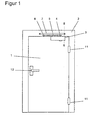
- FIG. 1 shows a schematic front view of a stop pivot door.
- the door has a door leaf 1, which is pivotally mounted on a vertical edge in bands 11 on the stationary door frame 2.
- the door leaf 1 is equipped with a sliding arm door closer 3 mounted on the floor.
- the Gleitarmtsch user 3 consists of a door closer housing 31, in the a closer shaft 4 is rotatably mounted. With the closer shaft 4 is rotatably on Sliding arm 5 is connected, which has at its free end a slider 6 which in a guide rail 7 is guided displaceably and rotatably.
- a closing spring not shown in the figures and a Damping device arranged, which cooperate with the closer shaft 4.
- the Gleitarmtsch Strukturer 3 may be a conventional built door closer act 3, z. B. a hydraulic door closer 3, as described in DE 36 38 353 A1.
- Such a door closer 3 works so that when manually opening the door 1 by the case resulting forced movement of the linkage and the closer shaft 4 the closer spring is tense.
- the closing process is carried out automatically under effect the closing spring. About hydraulic channels and valves while hydraulic medium exchanged between two piston working chambers of the piston-cylinder system.
- the so-called blade assembly that is Door closer housing 31 mounted on the door leaf 1.
- the slide 7 is on mounted on the frame 2.
- the so-called head assembly the door closer housing 31 is on the frame 2 mounted, and the slide rail 7 on the door leaf 1.
- the mounting can be both on the band side, as shown in Figure 1, as well as on the tape opposite side done.
- Door closers or door drives 3 for use on fire and fire doors had to be constructed in such a way that even with strong warming of the door closer, or door drive 3 no hydraulic fluid leaks.
- the surface temperature of the door can also be on the side away from the fire reach these places 300 ° to 400 ° C. Leaks through a leak Hydraulic oil would ignite immediately and favor an extension of the fire.
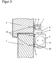
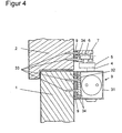
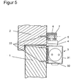
- FIGS. 2 to 5 each show a section along line II-II in FIG. 1.
- Figure 2 shows a cross section in the region of the fastening device of a hydraulic door closer 3 according to the prior art.
- the output shaft 4 of the door closer 3 is guided via a Gleitarmgestlinde 5 with a sliding body 6 in a mounted on the frame slide 7.
- the slide rail 7 is screwed at its axial ends with fastening screws 33 on the frame 2.
- the mounted on the door drive housing 31 is at its two front ends each equipped with a mounting foot 32.
- Each of the two mounting feet 32 has two holes for receiving fastening screws 33, which serve the attachment of the drive housing 31 on the door leaf 1.
- the fastening screws 33 of the drive housing 31 are made of plastic manufactured and designed as fuses. At temperatures above of 300 ° C, such as in the case of fire on the side facing away from the fire a fire door occur, the plastic melts and loses its Load capacity. Due to their own weight, the slide rail 7 and then release the door drive housing 31 including the linkage 5, 6, 7 from the door frame 2, or door 1 and fall to the ground. Without direct contact to the hot Door surface is on the side facing away from the fire The door now no danger that any escaping hydraulic oil ignites. On the fire side, it is quite possible that even on the door closer 3 lying on the floor is caught by the fire. This means, however safety-wise no danger, since in this case no spreading of the fire can take place on the brand-facing side of the door 1.
- Figure 3 shows a modification of Figure 2.
- the holes for receiving the mounting screws 33 in the slide rail 7 and in the mounting feet 32 of the drive housing 31 are each provided with plastic sleeves 8.
- the plastic sleeves 8 in turn take the mounting screws 33 and serve as a fuse.
- the sleeve diameter is chosen larger than the diameter of the respective screw head.
- the fastening screws 33 are made of highly thermally conductive material, for example metal, in particular copper or steel, which conduct heat in the event of a fire sufficiently quickly and to the plastic sleeves designed as a fuse.
- FIG. 4 shows a further alternative embodiment, which is particularly suitable for retrofitting existing door closers 3.
- both the slide rail 7 and the drive housing 31 are mounted on mounting plates 9 made of highly heat-insulating and low-slip plastic on the door frame 2 and the door 1.
- Sliding rail 7 and drive housing 31 are fastened by means of highly thermally conductive, non-melting metal mounting screws 34 on the mounting plate 9.
- the mounting screws 34 engage only in the respective mounting plate 9, but not in the door frame 2 and the door 1.
- the mounting plates 9 are in turn screwed with mounting screws 33 made of metal on the door frame 2, or door 1. In case of fire, the mounting plates 9 serve as fuses.
- the mounting screws 34 for mounting the drive housing 31 and slide 7 lose their grip when melting the mounting plate 9, and then as already described in Figure 2 fall the slide 7 and the door drive housing 31 including the linkage 5, 6, 7 to the ground. The reliable and complete melting of the fuse link is ensured by the high heat conduction of the screws.
- both the slide rail 7 and the mounting feet of the door drive housing 31 are made of plastic and bolted in a conventional manner with metallic screws 33 on the door frame 2, and the door leaf 1.
- the slide 7 and the mounting feet 32 act as a fuse.
- the slide 7 and the door drive housing 31 including the linkage 5, 6, 7 to the ground as soon as slide rail 7 and mounting feet 32 melt due to the heat and the fastening screws 33 thereby lose their hold.
- the highly thermally conductive and non-fusible screws ensure that the fuse in the area of the screws melts reliably and quickly.
- the fastening device with the fuse proves itself in all drives, when working with a flammable medium when using Fire and fire doors in a corresponding manner advantageous.
- Media can be hydraulic oil as described above, but also other media are conceivable.
- the media can be used to dampen the wing movement as described above in a damping device z. B. with piston-cylinder system be used.
- embodiments are also possible which have hydraulic clutches or hydraulic transmissions or clutches or gear with other flammable media.
Landscapes
- Business, Economics & Management (AREA)
- Emergency Management (AREA)
- Special Wing (AREA)
- Lock And Its Accessories (AREA)
- Power-Operated Mechanisms For Wings (AREA)
- Elevator Door Apparatuses (AREA)
Description
- Figur 1
- eine schematische Frontansicht einer Anschlagschwenktür mit einem aufliegend montierten Gleitarmtürschließer;
- Figur 2
- einen Schnitt entlang Linie II - II in Figur 1 mit einer Befestigung des Türschließers über Kunststoffschrauben gemäß dem Stand der Technik;
- Figur 3
- einen Schnitt entlang Linie II - II in Figur 1 mit einer Sicherung der Befestigung des Türschließers über Kunststoffhülsen;
- Figur 4
- einen Schnitt entlang Linie II - II in Figur 1 mit einer Montage des Türschließers auf Montageplatten aus Kunststoff;
- Figur 5
- einen Schnitt entlang Linie II - II in Figur 1 eines Türschließers mit Kunststoffgehäuse und Kunststoffgleitschiene.
- 1
- Türflügel
- 11
- Türband
- 12
- Türgriff
- 2
- Türrahmen
- 3
- Türschließer, Türantrieb
- 31
- Antriebsgehäuse
- 32
- Montagefuß
- 33
- Befestigungsschraube, erste Befestigungsmittel
- 34
- Montageschraube, zweite Befestigungsmittel
- 4
- Abtriebswelle, Schließerwelle
- 5
- Gleitarm
- 6
- Gleitkörper, Gleiter
- 7
- Gleitschiene
- 8
- Kunststoffhülse, Hülse
- 9
- Montageplatte
Claims (11)
- Türantrieb für den Türflügel (1) einer Brand- oder Feuerschutztür, mit einem Antriebsgehäuse (31),wobei das Dreh- oder Gleitlager (7) am Türflügel (1) oder an einem ortsfesten Türrahmen (2) und das Antriebsgehäuse (3) am ortsfesten Türrahmen (2) bzw. am Türflügel (1) über eine Befestigungsvorrichtung befestigt ist, wobei eine Schmelzsicherung (8, 9, 32) vorgesehen ist, die bei entsprechender Wärmeentwicklung im Brandfall schmilzt und die Befestigung des Antriebsgehäuses (31) am Türflügel (1) bzw. am Türrahmen (2) löst,mit einer in dem Antriebsgehäuse (31) angeordneten, motorischen Antriebsvorrichtung mit Fremdenergie zum Öffnen bzw. Schließen des Türflügels (1) und/oder mit einer in dem Antriebsgehäuse (31) angeordneten Rückstellvorrichtung, welche beim Öffnen des Türflügels (1) beaufschlagt wird und als Energiespeicher zum selbsttätigen Schließen des Türflügels (1) ausgebildet ist,mit einer in dem Antriebsgehäuse (31) angeordneten Dämpfungsvorrichtung zum Dämpfen der Schließ- und/oder Öffnungsbewegung des Türflügels,mit einem mit der motorischen Antriebseinrichtung und/oder der Rückstellvorrichtung und/oder der Dämpfungsvorrichtung zusammenwirkenden, im Antriebsgehäuse (31) gelagerten Abtriebsglied (4),mit einem kraftübertragenden Gestänge (5), welches einerseits mit dem Abtriebsglied (4) verbunden ist und andererseits in einem Dreh- oder Gleitlager (7) abgestützt ist,
dadurch gekennzeichnet, dassdass die Befestigungsvorrichtung des Antriebsgehäuses (31) am Türflügel (1) bzw. am Türrahmen (2) ein hoch wärmeleitendes, nicht, oder nur bei Temperaturen größer als 500°C schmelzendes Metallbefestigungsglied aufweist, welches im Bereich der Schmelzsicherung (8, 9, 32) zur Herstellung der Befestigung des Antriebsgehäuses am Türflügel bzw. am Türrahmen in die Schmelzsicherung (8, 9, 32) eingreifend angeordnet ist, und im Brandfall derart Wärme zur Schmelzsicherung (8, 9, 32) leitet, dass die Schmelzsicherung (8, 9, 32) im Bereich des Metallbefestigungsglieds schmilzt und dadurch die Befestigung des Antriebsgehäuses (31) am Türflügel (1) bzw. am Türrahmen (2) löst.die Schmelzsicherung (8, 9, 32) als eine im Brandfall schmelzende, separat ausgebildete oder einstückig mit dem Antriebsgehäuse (31) ausgebildete Montageplatte (9) aus schwach wärmeleitendem und/oder bei niedriger Temperatur schmelzendem Material, und/oderals eine im Brandfall schmelzende mit dem Antriebsgehäuse (31) einstückige Montageeinrichtung aus schwach wärmeleitendem Material, und/oderals eine im Brandfall schmelzende Sicherungshülse (8) aus einem bei niedriger Temperatur schmelzenden Material ausgebildet ist, und - Türantrieb nach Anspruch 1, dadurch gekennzeichnet, dass das Metallbefestigungsglied als Metallschraube (33) ausgebildet ist.
- Türantrieb nach Anspruch 2, dadurch gekennzeichnet, dass die Schmelzsicherung (8, 9, 32) eine Sicherungshülse (8) aus einem bei niedriger Temperatur schmelzenden Material aufweist, wobei die Sicherungshülse (8) in einer Befestigungsbohrung des Antriebsgehäuses (31) aufgenommen ist, und wobei der Außendurchmesser der Hülse (8) größer ist, als der Durchmesser des Schraubenkopfes der jeweiligen Metallschraube (33).
- Türantrieb nach Anspruch 1, dadurch gekennzeichnet, dass die Schmelzsicherung (8, 9, 32) eine Montageplatte (9) aus einem schwach wärmeleitenden und/oder bei niedriger Temperatur schmelzenden Material aufweist,
wobei die Montageplatte (9) auf dem Türflügel (1) bzw. Türrahmen (2) über erste Befestigungsmittel (33) mit einem hoch wärmeleitenden Metallbefestigungsglied befestigt wird und das Antriebsgehäuse (31) auf der Montageplatte (9) über zweite Befestigungsmittel (34) mit einem hoch wärmeleitenden Metallbefestigungsglied befestigt wird,
und wobei die zweiten Befestigungsmittel (34) zur Befestigung des Antriebsgehäuses (31) auf der Montageplatte (9) lediglich in die Montageplatte (9) und nicht in den Türflügel (1) bzw. den Türrahmen (2) eingreifen. - Türantrieb nach Anspruch 1, dadurch gekennzeichnet, dass das Antriebsgehäuse (31) des Türantriebs (3) zumindest teilweise aus einem schwach wärmeleitenden und/oder bei niedriger Temperatur schmelzenden Material besteht.
- Türantrieb nach Anspruch 1, dadurch gekennzeichnet, dass die Befestigungsvorrichtung des Dreh- oder Gleitlagers (7) am Türrahmen (2) bzw. am Türflügel (1) ein hoch wärmeleitendes, nicht, oder nur bei Temperaturen größer als 500°C schmelzendes Metallbefestigungsglied aufweist, welches im Bereich einer Schmelzsicherung (8, 9, 32) angeordnet ist, welche im Brandfall bei entsprechender Wärmeentwicklung schmilzt und die Befestigung des Dreh- oder Gleitlagers (7) am Türrahmen (2) bzw. am Türflügel (1) löst.
- Türantrieb nach Anspruch 6, dadurch gekennzeichnet, dass das Metallbefestigungsglied als Metallschraube ausgebildet ist.
- Türantrieb nach Anspruch 7 , dadurch gekennzeichnet, dass die Schmelzsicherung (8, 9, 32) eine Sicherungshülse (8) aus einem bei niedriger Temperatur schmelzenden Material aufweist, wobei die Sicherungshülse (8) in einer Befestigungsbohrung des Dreh- oder Gleitlagers (7) aufgenommen ist,
und wobei der Außendurchmesser der Hülse (8) größer ist, als der Durchmesser des Schraubenkopfes der jeweiligen Metallschraube (33). - Türantrieb nach Anspruch 8, dadurch gekennzeichnet, dass die Schmelzsicherung (8, 9, 32) der Befestigungsvorrichtung eine Montageplatte (9) aus einem bei niedriger Temperatur schmelzenden Material aufweist,
wobei die Montageplatte (9) auf dem Türflügel (1) bzw. Türrahmen (2) über erste Befestigungsmittel (33) mit einem hoch wärmeleitenden Metallbefestigungsglied befestigt wird, und das Dreh- oder Gleitlager (7) auf der Montageplatte (9) über zweite Befestigungsmittel (34) mit einem hoch wärmeleitenden Metallbefestigungsglied befestigt wird,
und wobei die zweiten Befestigungsmittel (34) zur Befestigung des Dreh- oder Gleitlagers (7) auf der Montageplatte (9) lediglich in die Montageplatte (9) und nicht in den Türflügel (1) bzw. den Türrahmen (2) eingreifen. - Türantrieb nach Anspruch 6, dadurch gekennzeichnet, dass das kraftübertragende Gestänge (5, 6) des Türantriebs (3) zumindest teilweise aus einem schwach wärmeleitenden und/oder bei niedriger Temperatur schmelzenden Material besteht.
- Türantrieb nach Anspruch 10, dadurch gekennzeichnet, dass das Dreh- oder Gleitlager (7), in welchem sich das kraftübertragende Gestänge (5, 6) abstützt, zumindest teilweise aus einem schwach wärmeleitenden und/oder bei niedriger Temperatur schmelzenden Material besteht.
Applications Claiming Priority (3)
| Application Number | Priority Date | Filing Date | Title |
|---|---|---|---|
| DE19726741A DE19726741A1 (de) | 1997-06-24 | 1997-06-24 | Türantrieb |
| DE19726741 | 1997-06-24 | ||
| PCT/DE1998/001727 WO1998059141A1 (de) | 1997-06-24 | 1998-06-24 | Türantrieb |
Publications (3)
| Publication Number | Publication Date |
|---|---|
| EP0991840A1 EP0991840A1 (de) | 2000-04-12 |
| EP0991840B1 true EP0991840B1 (de) | 2005-03-30 |
| EP0991840B2 EP0991840B2 (de) | 2012-11-07 |
Family
ID=7833465
Family Applications (1)
| Application Number | Title | Priority Date | Filing Date |
|---|---|---|---|
| EP98942460A Expired - Lifetime EP0991840B2 (de) | 1997-06-24 | 1998-06-24 | Türantrieb |
Country Status (7)
| Country | Link |
|---|---|
| US (1) | US6363575B1 (de) |
| EP (1) | EP0991840B2 (de) |
| CN (1) | CN1265171A (de) |
| AT (1) | ATE292228T1 (de) |
| AU (1) | AU9060898A (de) |
| DE (4) | DE19726741A1 (de) |
| WO (1) | WO1998059141A1 (de) |
Families Citing this family (18)
| Publication number | Priority date | Publication date | Assignee | Title |
|---|---|---|---|---|
| SG122774A1 (en) * | 2002-12-16 | 2006-06-29 | Malaysia Woodworking Pte Ltd | Mounting of laminates to fire doors |
| DE102004052283B3 (de) * | 2004-10-27 | 2005-12-22 | Dorma Gmbh + Co. Kg | Gleitschiene |
| US20060192395A1 (en) * | 2005-02-25 | 2006-08-31 | Mccabe Francis J | Releasable, resettable latch mechanism |
| ES2320068B1 (es) * | 2006-10-24 | 2010-02-26 | Rubio Carpinteria Metalica Y Cerrajeria S.L. | Dispositivo interruptor de calor para puerta cortafuegos. |
| WO2012119397A1 (zh) * | 2011-08-18 | 2012-09-13 | 华为技术有限公司 | 机房及其消防天窗 |
| CA2801443A1 (en) * | 2012-01-10 | 2013-07-10 | Stoebich Brandschutz Gmbh | Fire and smoke protection system |
| DE102012111539A1 (de) * | 2012-11-28 | 2014-05-28 | Dorma Gmbh + Co. Kg | Türbetätiger |
| WO2016113431A1 (de) * | 2015-01-18 | 2016-07-21 | Assa Abloy Sicherheitstechnik Gmbh | Türantriebseinrichtung mit hauptantrieb und hilfsantrieb |
| DE102015102919A1 (de) * | 2015-03-02 | 2016-09-08 | Dorma Deutschland Gmbh | Anordnung für eine Tür |
| DE102015102914A1 (de) * | 2015-03-02 | 2016-09-22 | Dorma Deutschland Gmbh | Feststellanordnung sowie Türbetätiger mit Feststellanordnung |
| CN105804442A (zh) * | 2016-03-15 | 2016-07-27 | 成都爆米花信息技术有限公司 | 一种散热机房系统 |
| CN106761111B (zh) * | 2017-01-03 | 2018-01-16 | 苏州市富尔达科技股份有限公司 | 一种活动式闭窗器 |
| DE102017201809B4 (de) * | 2017-02-06 | 2022-06-09 | Geze Gmbh | Antrieb für einen tür- oder fensterflügel |
| CN110259352A (zh) * | 2019-07-03 | 2019-09-20 | 湖南坚致幕墙安装设计有限公司 | 强制归零式防火窗 |
| EP3926137B1 (de) * | 2020-06-15 | 2025-08-06 | dormakaba Deutschland GmbH | Montagekonsole für einen türbetätiger |
| EP3943697B1 (de) * | 2020-07-20 | 2025-03-19 | dormakaba Deutschland GmbH | Anordnung umfassend einen türbetätiger und und eine brandschutzbefestigungseinrichtung |
| US12385309B2 (en) | 2020-09-07 | 2025-08-12 | Dormakaba Deutschland Gmbh | Linkage for a door actuator |
| EP4012141B1 (de) * | 2020-12-14 | 2025-03-19 | dormakaba Deutschland GmbH | Montagekonsole für einen türbetätiger |
Family Cites Families (21)
| Publication number | Priority date | Publication date | Assignee | Title |
|---|---|---|---|---|
| DE33565C (de) † | J. A. HOUSE in Bridgeport, County of Fairfield, State of Connecticut, V. St. A | Selbstthätiger Feuerlöschapparat | ||
| DE29294C (de) † | M. RUTHENBURG in Cincinnati, Ohio, Amerika | Neuerung im Verfahren und an Apparaten zum Feuerlöschen | ||
| US1520750A (en) † | 1920-02-28 | 1924-12-30 | Executrix Emma A Hodgman | Fusible link |
| US1539311A (en) † | 1922-02-11 | 1925-05-26 | Executrix Emma A Hodgman | Fusible link |
| US1934279A (en) † | 1929-06-19 | 1933-11-07 | Rockwood Sprinkler Co Massachusetts | Fusible link |
| CH281690A (de) * | 1950-05-25 | 1952-03-31 | Gmbh Hs Murbach | Türschliesser. |
| DE1559617A1 (de) † | 1965-12-14 | 1969-10-16 | Ceag Concordia Elek Zitaets Ag | Schmelzlotglied fuer die automatische Ausloesung von Brandloesch- und Feuerschutzvorrichtungen |
| US3759556A (en) * | 1971-04-05 | 1973-09-18 | A Wright | Emergency releasing safety apparatus |
| US4161804A (en) | 1977-12-21 | 1979-07-24 | Rixson-Firemark, Inc. | Heat-actuated door latch |
| US4265051A (en) * | 1978-01-12 | 1981-05-05 | Williams Clarence E | Door having improved closing and latching systems |
| JPS58178777A (ja) * | 1982-04-12 | 1983-10-19 | 千蔵工業株式会社 | スイングドアの自動開閉装置 |
| DE3411576C1 (de) * | 1983-08-17 | 1985-02-07 | Dieter 2875 Ganderkesee Schmidt | Sicherheitsventil |
| DE3638353C3 (de) * | 1985-07-05 | 1997-06-19 | Geze Grundstueck Beteiligung | Türschließer |
| US4805261A (en) * | 1987-10-08 | 1989-02-21 | Safe-Air Of Illinois, Inc. | Resettable fire link |
| US4851979A (en) * | 1988-06-16 | 1989-07-25 | Cooper Industries, Inc. | Light diffuser mounting system |
| DE4002747C3 (de) * | 1990-01-31 | 2002-09-05 | Geze Gmbh | Elektrohydraulische Antriebseinheit |
| KR930001035Y1 (ko) * | 1990-07-31 | 1993-03-08 | 주식회사 동광 | 유압도어 클로우져 |
| US5121950A (en) * | 1991-04-23 | 1992-06-16 | The Stanley Works | Heat activated spring loaded locking bolt for hinged doors and door assemblies employing same |
| US5529148A (en) * | 1993-08-24 | 1996-06-25 | O'leary; Thomas M. | Automatic brake and hold mechanism for sliding rods |
| GB2315808B (en) * | 1994-04-25 | 1998-09-02 | Schlage Lock Co | Door closer for the non-fire side of a fire-door safety installation |
| CA2147584C (en) * | 1994-04-25 | 2001-08-14 | Rex H. Lasson | Door closer for the non-fire side of a fire-door safety installation |
-
1997
- 1997-06-24 DE DE19726741A patent/DE19726741A1/de not_active Withdrawn
-
1998
- 1998-06-24 DE DE59812693T patent/DE59812693D1/de not_active Expired - Lifetime
- 1998-06-24 EP EP98942460A patent/EP0991840B2/de not_active Expired - Lifetime
- 1998-06-24 CN CN98807492A patent/CN1265171A/zh active Pending
- 1998-06-24 DE DE29880074U patent/DE29880074U1/de not_active Expired - Lifetime
- 1998-06-24 DE DE19880777T patent/DE19880777D2/de not_active Expired - Lifetime
- 1998-06-24 WO PCT/DE1998/001727 patent/WO1998059141A1/de not_active Ceased
- 1998-06-24 AT AT98942460T patent/ATE292228T1/de active
- 1998-06-24 US US09/446,716 patent/US6363575B1/en not_active Expired - Fee Related
- 1998-06-24 AU AU90608/98A patent/AU9060898A/en not_active Abandoned
Also Published As
| Publication number | Publication date |
|---|---|
| WO1998059141A1 (de) | 1998-12-30 |
| DE29880074U1 (de) | 2000-04-20 |
| ATE292228T1 (de) | 2005-04-15 |
| EP0991840A1 (de) | 2000-04-12 |
| US6363575B1 (en) | 2002-04-02 |
| DE59812693D1 (de) | 2005-05-04 |
| AU9060898A (en) | 1999-01-04 |
| EP0991840B2 (de) | 2012-11-07 |
| DE19880777D2 (de) | 2000-06-15 |
| CN1265171A (zh) | 2000-08-30 |
| DE19726741A1 (de) | 1999-01-07 |
Similar Documents
| Publication | Publication Date | Title |
|---|---|---|
| EP0991840B2 (de) | Türantrieb | |
| EP0662185B1 (de) | Schwenktürantrieb | |
| DE19515169C2 (de) | Türschließer für eine Brandschutz-Sicherheitstür | |
| EP0141902A2 (de) | Vorrichtung zur Regelung der Schliessfolge von zweiflügeligen Türen | |
| EP3916183A1 (de) | Türbetätiger zum öffnen und/oder schliessen einer tür | |
| DE19538482C1 (de) | Hydraulischer Servotürschließer | |
| EP1431497B1 (de) | Freilaufvorrichtung für den Antrieb eines Flügels einer Tür oder eines Fensters | |
| DE19545401A1 (de) | Schließfolgesteuerung für eine zweiflügelige Tür | |
| EP1231346B1 (de) | Scharniergelenk | |
| DE19532262B4 (de) | Vorrichtung zur Schließfolgeregelung für zweiflügelige Türen | |
| DE2754779A1 (de) | Nockengetriebener feder-rueckholmechanismus, dessen ausgangsmoment eine funktion des nockenprofils ist, sowie verfahren zu seiner herstellung | |
| EP1801336A1 (de) | Schliessfolgeregelung | |
| DE2658149C2 (de) | Feuerschutzvorrichtung | |
| EP1473431A1 (de) | Türschliessvorrichtung für Notfälle mit Freilauf-Normalbetrieb | |
| DE102005062051B4 (de) | Vorrichtung zur Schließfolgeregelung für zweiflügelige Drehtüren | |
| DE8808393U1 (de) | Vorrichtung zum automatischen Verschließen eines Rohres | |
| DE2512931B2 (de) | Absperrventil | |
| DE19543664A1 (de) | Spindeltrieb zum Ausstellen eines Flügels | |
| DE102019209262B4 (de) | Antrieb für einen tür- oder fensterflügel | |
| WO2025219441A1 (de) | Brandschutzverglasung mit einer sicherheitseinrichtung | |
| DE102020206544B4 (de) | Gestänge für einen Türschließer oder Türantrieb, Türschließer oder Türantrieb sowie Tür | |
| DE102019209260B4 (de) | Antrieb für einen tür- oder fensterflügel | |
| EP0782657B2 (de) | Feuerschutz-tür | |
| DE102017201809B4 (de) | Antrieb für einen tür- oder fensterflügel | |
| EP1764451B1 (de) | Beschlag für eine Feuerschutz-Toranlage |
Legal Events
| Date | Code | Title | Description |
|---|---|---|---|
| PUAI | Public reference made under article 153(3) epc to a published international application that has entered the european phase |
Free format text: ORIGINAL CODE: 0009012 |
|
| 17P | Request for examination filed |
Effective date: 20000121 |
|
| AK | Designated contracting states |
Kind code of ref document: A1 Designated state(s): AT CH DE FI FR GB IT LI SE |
|
| 17Q | First examination report despatched |
Effective date: 20040311 |
|
| GRAP | Despatch of communication of intention to grant a patent |
Free format text: ORIGINAL CODE: EPIDOSNIGR1 |
|
| GRAS | Grant fee paid |
Free format text: ORIGINAL CODE: EPIDOSNIGR3 |
|
| GRAA | (expected) grant |
Free format text: ORIGINAL CODE: 0009210 |
|
| AK | Designated contracting states |
Kind code of ref document: B1 Designated state(s): AT CH DE FI FR GB IT LI SE |
|
| REG | Reference to a national code |
Ref country code: GB Ref legal event code: FG4D Free format text: NOT ENGLISH |
|
| REG | Reference to a national code |
Ref country code: CH Ref legal event code: NV Representative=s name: E. BLUM & CO. PATENTANWAELTE Ref country code: CH Ref legal event code: EP |
|
| REG | Reference to a national code |
Ref country code: SE Ref legal event code: TRGR |
|
| GBT | Gb: translation of ep patent filed (gb section 77(6)(a)/1977) |
Effective date: 20050401 |
|
| REF | Corresponds to: |
Ref document number: 59812693 Country of ref document: DE Date of ref document: 20050504 Kind code of ref document: P |
|
| PLBI | Opposition filed |
Free format text: ORIGINAL CODE: 0009260 |
|
| PLAX | Notice of opposition and request to file observation + time limit sent |
Free format text: ORIGINAL CODE: EPIDOSNOBS2 |
|
| 26 | Opposition filed |
Opponent name: DORMA GMBH + CO. KG Effective date: 20051222 |
|
| ET | Fr: translation filed | ||
| PLBB | Reply of patent proprietor to notice(s) of opposition received |
Free format text: ORIGINAL CODE: EPIDOSNOBS3 |
|
| REG | Reference to a national code |
Ref country code: CH Ref legal event code: PFA Owner name: GEZE GMBH Free format text: GEZE GMBH#REINHOLD-VOESTER-STRASSE 21-29#71229 LEONBERG (DE) -TRANSFER TO- GEZE GMBH#REINHOLD-VOESTER-STRASSE 21-29#71229 LEONBERG (DE) |
|
| APAH | Appeal reference modified |
Free format text: ORIGINAL CODE: EPIDOSCREFNO |
|
| APBM | Appeal reference recorded |
Free format text: ORIGINAL CODE: EPIDOSNREFNO |
|
| APBP | Date of receipt of notice of appeal recorded |
Free format text: ORIGINAL CODE: EPIDOSNNOA2O |
|
| APBQ | Date of receipt of statement of grounds of appeal recorded |
Free format text: ORIGINAL CODE: EPIDOSNNOA3O |
|
| APBU | Appeal procedure closed |
Free format text: ORIGINAL CODE: EPIDOSNNOA9O |
|
| PGFP | Annual fee paid to national office [announced via postgrant information from national office to epo] |
Ref country code: FI Payment date: 20120613 Year of fee payment: 15 Ref country code: SE Payment date: 20120621 Year of fee payment: 15 |
|
| PUAH | Patent maintained in amended form |
Free format text: ORIGINAL CODE: 0009272 |
|
| STAA | Information on the status of an ep patent application or granted ep patent |
Free format text: STATUS: PATENT MAINTAINED AS AMENDED |
|
| 27A | Patent maintained in amended form |
Effective date: 20121107 |
|
| AK | Designated contracting states |
Kind code of ref document: B2 Designated state(s): AT CH DE FI FR GB IT LI SE |
|
| REG | Reference to a national code |
Ref country code: CH Ref legal event code: AELC |
|
| REG | Reference to a national code |
Ref country code: DE Ref legal event code: R102 Ref document number: 59812693 Country of ref document: DE Effective date: 20121107 |
|
| PGFP | Annual fee paid to national office [announced via postgrant information from national office to epo] |
Ref country code: IT Payment date: 20120628 Year of fee payment: 15 |
|
| PGFP | Annual fee paid to national office [announced via postgrant information from national office to epo] |
Ref country code: AT Payment date: 20120613 Year of fee payment: 15 |
|
| REG | Reference to a national code |
Ref country code: SE Ref legal event code: ECNC |
|
| PG25 | Lapsed in a contracting state [announced via postgrant information from national office to epo] |
Ref country code: FI Free format text: LAPSE BECAUSE OF FAILURE TO SUBMIT A TRANSLATION OF THE DESCRIPTION OR TO PAY THE FEE WITHIN THE PRESCRIBED TIME-LIMIT Effective date: 20121107 |
|
| PG25 | Lapsed in a contracting state [announced via postgrant information from national office to epo] |
Ref country code: IT Free format text: LAPSE BECAUSE OF NON-PAYMENT OF DUE FEES Effective date: 20130624 |
|
| REG | Reference to a national code |
Ref country code: AT Ref legal event code: MM01 Ref document number: 292228 Country of ref document: AT Kind code of ref document: T Effective date: 20140624 |
|
| PG25 | Lapsed in a contracting state [announced via postgrant information from national office to epo] |
Ref country code: AT Free format text: LAPSE BECAUSE OF NON-PAYMENT OF DUE FEES Effective date: 20140624 |
|
| REG | Reference to a national code |
Ref country code: FR Ref legal event code: PLFP Year of fee payment: 18 |
|
| PGFP | Annual fee paid to national office [announced via postgrant information from national office to epo] |
Ref country code: GB Payment date: 20150618 Year of fee payment: 18 Ref country code: CH Payment date: 20150618 Year of fee payment: 18 |
|
| PG25 | Lapsed in a contracting state [announced via postgrant information from national office to epo] |
Ref country code: SE Free format text: LAPSE BECAUSE OF NON-PAYMENT OF DUE FEES Effective date: 20130625 |
|
| PGFP | Annual fee paid to national office [announced via postgrant information from national office to epo] |
Ref country code: FR Payment date: 20150619 Year of fee payment: 18 |
|
| PGFP | Annual fee paid to national office [announced via postgrant information from national office to epo] |
Ref country code: DE Payment date: 20160630 Year of fee payment: 19 |
|
| REG | Reference to a national code |
Ref country code: CH Ref legal event code: PL |
|
| GBPC | Gb: european patent ceased through non-payment of renewal fee |
Effective date: 20160624 |
|
| REG | Reference to a national code |
Ref country code: FR Ref legal event code: ST Effective date: 20170228 |
|
| PG25 | Lapsed in a contracting state [announced via postgrant information from national office to epo] |
Ref country code: LI Free format text: LAPSE BECAUSE OF NON-PAYMENT OF DUE FEES Effective date: 20160630 Ref country code: CH Free format text: LAPSE BECAUSE OF NON-PAYMENT OF DUE FEES Effective date: 20160630 Ref country code: FR Free format text: LAPSE BECAUSE OF NON-PAYMENT OF DUE FEES Effective date: 20160630 |
|
| REG | Reference to a national code |
Ref country code: DE Ref legal event code: R231 Ref document number: 59812693 Country of ref document: DE |
|
| PG25 | Lapsed in a contracting state [announced via postgrant information from national office to epo] |
Ref country code: GB Free format text: LAPSE BECAUSE OF NON-PAYMENT OF DUE FEES Effective date: 20160624 |
|
| PG25 | Lapsed in a contracting state [announced via postgrant information from national office to epo] |
Ref country code: DE Free format text: LAPSE BECAUSE OF THE APPLICANT RENOUNCES Effective date: 20170530 |