EP0990494A1 - Machine pour fragmenter des blocs d'une matiere organique naturelle ou synthetique, telle que du bois - Google Patents
Machine pour fragmenter des blocs d'une matiere organique naturelle ou synthetique, telle que du bois Download PDFInfo
- Publication number
- EP0990494A1 EP0990494A1 EP99402341A EP99402341A EP0990494A1 EP 0990494 A1 EP0990494 A1 EP 0990494A1 EP 99402341 A EP99402341 A EP 99402341A EP 99402341 A EP99402341 A EP 99402341A EP 0990494 A1 EP0990494 A1 EP 0990494A1
- Authority
- EP
- European Patent Office
- Prior art keywords
- basket
- machine according
- cutting
- channel
- previous
- Prior art date
- Legal status (The legal status is an assumption and is not a legal conclusion. Google has not performed a legal analysis and makes no representation as to the accuracy of the status listed.)
- Granted
Links
Images


Classifications
-
- B—PERFORMING OPERATIONS; TRANSPORTING
- B26—HAND CUTTING TOOLS; CUTTING; SEVERING
- B26D—CUTTING; DETAILS COMMON TO MACHINES FOR PERFORATING, PUNCHING, CUTTING-OUT, STAMPING-OUT OR SEVERING
- B26D7/00—Details of apparatus for cutting, cutting-out, stamping-out, punching, perforating, or severing by means other than cutting
- B26D7/06—Arrangements for feeding or delivering work of other than sheet, web, or filamentary form
- B26D7/0666—Arrangements for feeding or delivering work of other than sheet, web, or filamentary form by screw or rotary spiral conveyors
-
- B—PERFORMING OPERATIONS; TRANSPORTING
- B02—CRUSHING, PULVERISING, OR DISINTEGRATING; PREPARATORY TREATMENT OF GRAIN FOR MILLING
- B02C—CRUSHING, PULVERISING, OR DISINTEGRATING IN GENERAL; MILLING GRAIN
- B02C18/00—Disintegrating by knives or other cutting or tearing members which chop material into fragments
- B02C18/06—Disintegrating by knives or other cutting or tearing members which chop material into fragments with rotating knives
- B02C18/16—Details
- B02C18/22—Feed or discharge means
-
- B—PERFORMING OPERATIONS; TRANSPORTING
- B26—HAND CUTTING TOOLS; CUTTING; SEVERING
- B26D—CUTTING; DETAILS COMMON TO MACHINES FOR PERFORATING, PUNCHING, CUTTING-OUT, STAMPING-OUT OR SEVERING
- B26D1/00—Cutting through work characterised by the nature or movement of the cutting member or particular materials not otherwise provided for; Apparatus or machines therefor; Cutting members therefor
- B26D1/01—Cutting through work characterised by the nature or movement of the cutting member or particular materials not otherwise provided for; Apparatus or machines therefor; Cutting members therefor involving a cutting member which does not travel with the work
- B26D1/12—Cutting through work characterised by the nature or movement of the cutting member or particular materials not otherwise provided for; Apparatus or machines therefor; Cutting members therefor involving a cutting member which does not travel with the work having a cutting member moving about an axis
- B26D1/25—Cutting through work characterised by the nature or movement of the cutting member or particular materials not otherwise provided for; Apparatus or machines therefor; Cutting members therefor involving a cutting member which does not travel with the work having a cutting member moving about an axis with a non-circular cutting member
- B26D1/34—Cutting through work characterised by the nature or movement of the cutting member or particular materials not otherwise provided for; Apparatus or machines therefor; Cutting members therefor involving a cutting member which does not travel with the work having a cutting member moving about an axis with a non-circular cutting member moving about an axis parallel to the line of cut
- B26D1/36—Cutting through work characterised by the nature or movement of the cutting member or particular materials not otherwise provided for; Apparatus or machines therefor; Cutting members therefor involving a cutting member which does not travel with the work having a cutting member moving about an axis with a non-circular cutting member moving about an axis parallel to the line of cut and rotating continuously in one direction during cutting, e.g. mounted on a rotary cylinder
-
- B—PERFORMING OPERATIONS; TRANSPORTING
- B26—HAND CUTTING TOOLS; CUTTING; SEVERING
- B26D—CUTTING; DETAILS COMMON TO MACHINES FOR PERFORATING, PUNCHING, CUTTING-OUT, STAMPING-OUT OR SEVERING
- B26D7/00—Details of apparatus for cutting, cutting-out, stamping-out, punching, perforating, or severing by means other than cutting
- B26D7/06—Arrangements for feeding or delivering work of other than sheet, web, or filamentary form
- B26D7/0641—Arrangements for feeding or delivering work of other than sheet, web, or filamentary form using chutes, hoppers, magazines
-
- B—PERFORMING OPERATIONS; TRANSPORTING
- B27—WORKING OR PRESERVING WOOD OR SIMILAR MATERIAL; NAILING OR STAPLING MACHINES IN GENERAL
- B27L—REMOVING BARK OR VESTIGES OF BRANCHES; SPLITTING WOOD; MANUFACTURE OF VENEER, WOODEN STICKS, WOOD SHAVINGS, WOOD FIBRES OR WOOD POWDER
- B27L11/00—Manufacture of wood shavings, chips, powder, or the like; Tools therefor
- B27L11/002—Transporting devices for wood or chips
-
- B—PERFORMING OPERATIONS; TRANSPORTING
- B27—WORKING OR PRESERVING WOOD OR SIMILAR MATERIAL; NAILING OR STAPLING MACHINES IN GENERAL
- B27L—REMOVING BARK OR VESTIGES OF BRANCHES; SPLITTING WOOD; MANUFACTURE OF VENEER, WOODEN STICKS, WOOD SHAVINGS, WOOD FIBRES OR WOOD POWDER
- B27L11/00—Manufacture of wood shavings, chips, powder, or the like; Tools therefor
- B27L11/005—Tools therefor
-
- B—PERFORMING OPERATIONS; TRANSPORTING
- B27—WORKING OR PRESERVING WOOD OR SIMILAR MATERIAL; NAILING OR STAPLING MACHINES IN GENERAL
- B27L—REMOVING BARK OR VESTIGES OF BRANCHES; SPLITTING WOOD; MANUFACTURE OF VENEER, WOODEN STICKS, WOOD SHAVINGS, WOOD FIBRES OR WOOD POWDER
- B27L11/00—Manufacture of wood shavings, chips, powder, or the like; Tools therefor
- B27L11/02—Manufacture of wood shavings, chips, powder, or the like; Tools therefor of wood shavings or the like
Definitions
- the invention relates to a machine designed for fragment raw blocks of organic matter natural, such as wood, or synthetic, such than a polymer or a derived material.
- fragment here means either any operation consisting in particular of cutting, defibrate, reduce, or calibrate the treated material.
- the products obtained may in particular be presented, as the case may be, under the form of chips, chips, or fibers.
- the machine according to the invention can in particular be used for obtaining fibers for manufacturing particle board, paper, etc.
- the machine according to the invention can be used to treat or recycle certain products, as well as waste.
- Fragmentation of blocks of matter such as wood is made under optimal conditions when the three parameters of speed tangential of cut, the speed of advance of the product and the projection of the cutting blades are controlled.
- the pieces of wood are channeled in a pipe up to a horizontal or vertical disc with blades cutter positioned radially.
- Associated cylinders when driving control the advance of pieces of wood, at a generally adjustable speed that can be constant.
- Machines of this type allow to control two of the parameters that need to be controlled to work in the best conditions. These two parameters are the projection of the cutting blades and the speed of advance of the product.
- the speed of cutting is variable and scalable depending on the distance which separates the considered cutting area from the center of the disc. It is therefore not possible to control the speed tangential cutting. Therefore, this type of machine does not allow to work in the best conditions.
- peripheral basket machines with striker cutting blades are fixed in a static or rotating basket, parallel to its axle, and a central paddle wheel turns at great speed speed inside the trash.
- This type of machine allows you to control the projection cutting blades, as well as the cutting speed.
- the speed of advance of the products introduced in the center of the machine and centrifuged by the blades is random.
- this speed of advance which results from the centrifugal force applied to the processed products, decreases in proportion to the reduction in product volume during the operation of fragmentation.
- the product feed speed is not therefore not under control, nor the energy consumption of main engine. Therefore, this type of machine does not also does not allow working under conditions optimal.
- the subject of the invention is precisely a machine fragmentation of blocks of a material, such as wood, whose original design allows it to work in the best conditions, controlling both the tangential cutting speed, the speed of advance of the product, the projection of the blades of cut and power consumption of the main engine.
- this result is obtained by means of a machine to fragment blocks of a natural or synthetic organic matter, such as wood, characterized in that it further comprises at least one fixed block supply channel to fragment, the first end of which is located the outside of the trash and including a second end opens into the basket in front of the organs cutting, and block advance control means in the channel, capable of conveying said blocks to the cutting elements at a feed speed controlled.
- the machine according to the invention allows to master the times the tangential cutting speed and the speed in advance of the product, which is not the case in any existing machines.
- the machine according to the invention makes it possible to work under conditions optimal.
- the advance control means are suitable advancing the blocks at constant speed. Moreover, they preferably include means for adjusting the speed.
- regulation means sensitive to the energy absorbed by the control means rotation control the advance control means, to ensure a total consumption of energy appreciably constant.
- the means of advance control can take different forms. In the preferred embodiment of the invention, they include an Archimedes screw housed in the supply channel, as well as a motor drive this screw. Alternatively, the means of advance order can also consist of a actuator-pusher assembly.
- the cutting members are mounted on external anvils, integral with the basket, by removable fixing means.
- removable fixing means include preferably, for each cutting member, a corner of internal clamping capable of applying the cutting member against the anvil, under the effect of centrifugal force generated by the rotation of the basket, at least one connecting member connecting the clamping wedge to anvil it with a clearance allowing an assembly and a disassembly of the cutting member, as well as means elastic bands which tighten the clamping wedge the anvil, against the aforementioned game.
- Each link member can then include a screw, screwed in the clamping corner, through freely anvil and provided with a disassembly head accessible from outside the basket. Thanks to this arrangement, the cutting members can be easily disassembled and replaced by applying pressure on the disassembly heads of the corresponding screws.
- Each of the cutting members can in particular include a blade attached to a blade holder, for example by means of screws, positioning fingers or by interlocking.
- said channel comprises advantageously an emptying hatch in a part located outside the trash.
- the feed channel is preferably mobile, for example tilting or sliding, by compared to the trash.
- the feed channel can then be brought into a maintenance position, in which it is totally located outside of the basket.
- the rotating basket can be mounted coaxially inside a static basket including a cylindrical wall, alternately, graters and calibration zones. Percussion irons are then attached to the basket rotating, and mounted between it and the basket static, near the cylindrical wall of this last.
- the rotating basket is generally supported and surrounded by a fixed casing provided with an access hatch allowing replacement cutting members.
- the axis of the rotating basket is substantially horizontal and a single inclined and ascending feed channel leads near the upper generator of this basket.
- the axis of the rotating basket is substantially horizontal and two substantially horizontal supply channels enter the basket on either side of this one.
- the axis of the rotating basket is substantially vertical and multiple inclined and downward feed channels emerge into said basket.
- the machine comprises a frame 10, which rests on the soil 12 above a well 14.
- the frame 10 is provided with means, such as a bearing 16, capable of rotatably supporting a basket 18 in the shape of a drum.
- a bearing 16 capable of rotatably supporting a basket 18 in the shape of a drum.
- the axis 20 of the basket rotary 18 is substantially horizontal.
- Trash rotary 18 is placed above the well 14.
- Des means 22 for controlling the rotation of the basket 18, such as an electric motor carried by the frame 10, are provided to drive the basket 18 in rotation around its axis 20, via a shaft 24 mounted in bearing 16.
- the frame 10 comprises a casing 26 which envelops completely basket 18, except the part low of it located above the well 14.
- the basket 18 includes a flange 28, fixed in its central part to the shaft 24, a cylindrical part of section 30, which will be described in detail below, as well as an annular disc 32, connected to the periphery of the flange 28 by the cylindrical cutting part 30.
- the fragmentation machine further comprises a supply channel 34 whose axis is contained in a plane passing through the axis of rotation 20 from trash 18 and tilted, for example about 45 °, relative to this axis 20.
- the feed channel 34 is arranged in such a way that its lower end, closed, is located outside of basket 18 and of the frame 10, on the side opposite to the means 22 for controlling rotation.
- the high, open end of the supply channel 34 is placed inside the basket 18 and ends up in the latter at close proximity to the highest generator of the cutting region 30.
- the supply channel 34 passes through a formed opening in the casing 26 and it is fixed to the frame 10.
- the channel supply 34 also passes through an opening circular formed in the annular disc 32.
- Advance control means are associated with the supply channel 34, in order to convey at a speed pre-controlled blocks or pieces of the material to be fragmented up to the cylindrical part of section 30 of the basket 18, according to a movement ascending inside channel 34.
- these advance control means comprise a screw Archimedes 36 mounted coaxially in the canal supply 34, as well as a drive motor 38 of the screw 36, such as a regulated electric motor.
- the means advance order can also consist of a push cylinder or by any similar device.
- the blocks or pieces of material to be fragmented are introduced at the bottom of the feed channel 34, at the outside of the casing 26, by a chute or hopper vertical 40 opening directly into the part channel bass.
- the fragmentation machine according to the invention allows control both the speed of advance of the blocks of matter to be fragmented and the tangential speed of cut these blocks. Since the mastery of the protruding cutting blades is no problem particular, the machine according to the invention therefore allows to work in the best possible conditions.
- the advance control means constituted by the Archimedes screw 36 and motor 38 in the mode of shown, are designed so that they can ensure the advance of the blocks of material in the channel 34 at a constant speed.
- means for adjusting this speed are advantageously provided, for example at the engine 38.
- regulation means associated with the motor 38 can ensure consumption total of substantially constant energy on the machine.
- the regulatory means receive signals representative of the energy absorbed by the motor 22 ensuring the rotation control of the basket 18.
- the means of regulation determine, at from these signals, the energy remaining available for motor 38 and this is ordered in result.
- the cylindrical cutting part 30 of the basket 18 (figure 1) is in the form of anvils outside 46, positioned on a certain radius by relative to axis 20 of the basket and spaced circumferentially from each other by a small predetermined distance.
- each of the outer anvils 46 is integral with the basket 18 and its ends are fixed respectively to the flange 28 and to the annular disc 32 (figure 1).
- each of the anvils 46 includes an interchangeable cutting member 44.
- each anvil 46 has a recess 48 with a section approximately in form of V.
- each of the recesses 48 has a front flank 50 inclined at an angle ⁇ to a direction radial, as well as a rear flank 52 oriented radially.
- the front flank 50 of each of the recesses 48 has a recessed portion 54 whose shape is. complementary to that of the cutting member 44 and in which is housed this organ. More precisely, the cutting member 44 comprises a blade holder 56 which is housed in the bottom of the hollow part 54, as well as a cutting blade 58, fixed to the blade holder 56 and flush with the front flank 50 when the section 44 is placed in the recessed portion 54. The edge of cutting 60 of cutting blade 58 then protrudes forward and inward, over distances predetermined, respectively with respect to the anvil 46 and relative to a wear shoe 62 mounted at the inside of the anvil 46, on a clamping wedge interior 64.
- the wear shoe 62 is carried by the corner of internal tightening 64, whose shape is complementary that of the recess 48, in the form of a V and an angle a.
- the clamping wedge 64 is mounted in the recess 48 and connected to the anvil 46 by one or more organs of binding, such as screws 66. More specifically, each screw 66 is screwed into a tapped hole 68, machined in the clamping corner 64, and passes freely through a hole 70 practiced in anvil 46.
- the head 72 of the screw 66 located outside of anvil 46, is supported on the latter by by means of elastic means constituted, by example, by a stack of Belleville 74 washers.
- a washer 76 is advantageously interposed between the head 72 of the screw and the Belleville washers 74.
- the arrangement is such that the axes of the screws 66 are oriented substantially radially with respect to the axis from the trash.
- the clamping wedge interior 64, the connecting members constituted by the screw 66, as well as the elastic means constituted by the Belleville 74 washers form means of removable fixing of the cutting member 44.
- the section 44 can be easily disassembled and replaced by applying pressure to the head 72 of each of the screws 66. Under the effect of this pressure, the stack of Belleville 74 washers are compressed and the assembly constituted by the tightening corner 64, the wear shoe 72 and the screws 66 is moved radially towards the interior by sliding along the rear flank 52. The clearance of the screw 66 relative to the anvil 46 is determined such that the clamping wedge 64 and the wear shoe 62 are then spaced from the sidewall before 50 of the recess 48 over a sufficient distance to allow the extraction of the cutting member 44 out of the recessed portion 54.
- the elastic means constituted in this case by the stack of Belleville 74 washers, sufficient force to hold the cutting member 44 in the recessed portion 54.
- mounting the cutting blade 58 on the blade holder 56 can be made of different manners, without departing from the scope of the invention.
- the blade of section 58 can be fixed to the blade holder 56 by a or more screws 78.
- the blade 58 on the blade holder 56 can be ensured by interlocking.
- the blade holder 56 may in particular have one or more projections 80 who force fit into housing additional 82 machined in blade 58.
- the attachment of the blade 58 to the blade holder 56 is provided by positioning fingers 84 which are force-fitted into machined holes 86 and 88 respectively in the blade holder 56 and in the blade 58.
- a hatch (not shown) may be provided on the casing 26, opposite the cylindrical part of section 30 of basket 18.
- the supply channel 34 and the means of advance order associated with it can also be movably mounted on the frame 10. A pivoting or sliding the channel then allows completely clear the basket 18. This can thus be replaced by another basket equipped with example of new or resharpened cutters and rules.
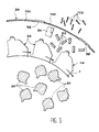
- the rotating basket 18 comprises, at the outside of the anvils 46, percussion irons 94 also oriented parallel to the axis of the basket.
- the number of percussion irons 94 is generally lower than that of anvils 46.
- a static basket 96 is interposed between the rotating basket and the casing 26 ( Figure 1) of the machine.
- This static basket 96 is fixed to the machine frame 10, near the irons of percussion 94. It essentially comprises a wall cylindrical which alternately includes, in the direction circumferential, 98 rasps and sizing zones 100.
- the rasps 98 are turned inwards and the calibration zones 100 are formed for example of grids or perforated plates, so as to form calibrated section passages.
- the inserts or chips 92 formed outside the anvils 46 are rotated by the irons of percussion 94 so as to be applied against graters 98 from the static basket 96.
- the fibers 102 thus formed pass through the calibration zones 100 when their section is small enough.
- the fragmented products collected in the well 14 of the machine are no longer pads or chips 92 as in the first mode embodiment described, but section fibers calibrated 102, which can in particular be used in the manufacture of particle board or paper.
- the invention is not limited to embodiments which have just been described in title of examples.
- the orientation of the axis of rotation 20 of the basket 18 as well as the number and orientation of supply channels 34 may be significantly different from those who have been described.
- a basket of horizontal axis but whose training in rotation is performed at its periphery, can be associated with two penetrating feed channels in the trash on either side of it and arranged substantially horizontally.
- the axis of rotation of the basket can be vertical.
- multiple channels inclined and descending feed can emerge simultaneously inside the basket.
Abstract
Description
- la figure 1 est une coupe schématique qui représente un premier mode de réalisation d'une machine de fragmentation conforme à l'invention ;
- la figure 2 est une coupe, à plus grande échelle, selon la ligne II-II de la figure 1 ;
- la figure 3 est une coupe illustrant, encore à plus grande échelle, l'un des organes de coupe de la machine et les moyens de fixation démontables associés ;
- les figures 4A, 4B et 4C sont des coupes à plus grande échelle illustrant trois exemples de montage d'une lame de coupe sur un porte-lame dans la machine selon l'invention ; et
- la figure 5 est une coupe comparable à la figure 2, illustrant un deuxième mode de réalisation d'une machine de fragmentation conforme à l'invention.
Claims (16)
- Machine pour fragmenter des blocs (90) d'une matière organique naturelle ou synthétique, telle que du bois, comprenant une corbeille rotative (18), apte à être entraínée en rotation autour d'un axe (20) par des moyens (22) de commande de rotation, ladite corbeille étant munie d'organes de coupe (44) orientés sensiblement parallèlement audit axe, la machine étant caractérisée en ce qu'elle comprend, de plus, au moins un canal fixe (34) d'alimentation en blocs (90) à fragmenter, dont une première extrémité est située à l'extérieur de la corbeille et dont une deuxième extrémité débouche dans la corbeille (18) devant les organes de coupe (44), et des moyens (36, 38) de commande d'avance des blocs (90) dans le canal (34), aptes à acheminer lesdits blocs jusqu'aux organes de coupe à une vitesse d'avance contrôlée.
- Machine selon la revendication 1, dans laquelle les moyens (36, 38) de commande d'avance sont aptes à faire avancer les blocs (90) à vitesse constante.
- Machine selon la revendication 2, dans laquelle les moyens (36, 38) de commande d'avance incluent des moyens de réglage de ladite vitesse constante.
- Machine selon la revendication 1, dans laquelle des moyens de régulation, sensibles à l'énergie absorbée par les moyens (22) de commande de rotation, pilotent les moyens (26, 38) de commande d'avance, pour assurer une consommation totale d'énergie sensiblement constante.
- Machine selon l'une quelconque des revendications précédentes, dans laquelle les moyens de commande d'avance comprennent une vis d'Archimède (36) logée dans le canal (34), et un moteur (38) d'entraínement de ladite vis.
- Machine selon l'une quelconque des revendications précédentes, dans laquelle les organes de coupe (44) sont montés sur des enclumes extérieures (46), solidaires de la corbeille (18), par des moyens de fixation démontables.
- Machine selon la revendication 6, dans laquelle les moyens de fixation comprennent, pour chaque organe de coupe (44), un coin de serrage intérieur (64) apte à appliquer l'organe de coupe contre l'enclume (46), sous l'effet de la force centrifuge engendrée par une rotation de la corbeille, au moins un organe de liaison (66) reliant le coin de serrage (64) à l'enclume (46) avec un jeu autorisant un montage et un démontage de l'organe de coupe (44), et des moyens élastiques (74) sollicitant le coin de serrage (64) vers l'enclume (46), à l'encontre dudit jeu.
- Machine selon la revendication 7, dans laquelle chaque organe de liaison comprend une vis (66), vissée dans le coin de serrage (64), traversant librement l'enclume (46) et munie d'une tête de démontage (72) accessible depuis l'extérieur de la corbeille (18).
- Machine selon l'une quelconque des revendications précédentes, dans laquelle chaque organe de coupe (44) comprend une lame (58) fixée sur un porte-lame (56).
- Machine selon l'une quelconque des revendications précédentes, dans laquelle le canal (34) comprend une trappe (35) de vidage dans une partie située à l'extérieur de la corbeille (18).
- Machine selon l'une quelconque des revendications précédentes, dans laquelle le canal (34) est mobile par rapport à la corbeille (18), de façon à pouvoir être amené dans une position de maintenance, dans laquelle le canal (34) est totalement situé à l'extérieur de la corbeille.
- Machine selon l'une quelconque des revendications précédentes, dans laquelle la corbeille rotative (18) est montée coaxialement à l'intérieur d'une corbeille statique (96) dont une paroi cylindrique inclut, de façon alternée, des râpes (98) et des zones de calibrage (100), des fers de percussion (94) fixés à la corbeille rotative (18) étant montés entre celle-ci et la corbeille statique (96), à proximité de sa paroi cylindrique.
- Machine selon l'une quelconque des revendications précédentes, dans laquelle la corbeille rotative (18) est entourée par un carter fixe (26), pourvu d'une trappe d'accès aux organes de coupe (44).
- Machine selon l'une quelconque des revendications précédentes, dans laquelle l'axe de la corbeille rotative (18) est sensiblement horizontal et un seul canal d'alimentation (34) incliné et ascendant débouche à proximité de la génératrice supérieure de ladite corbeille rotative.
- Machine selon l'une quelconque des revendications 1 à 13, dans laquelle l'axe de la corbeille rotative (18) est sensiblement horizontal et deux canaux d'alimentation (34) sensiblement horizontaux pénètrent dans la corbeille rotative, de part et d'autre de celle-ci.
- Machine selon l'une quelconque des revendications 1 à 13, dans laquelle l'axe de la corbeille rotative (18) est sensiblement vertical et plusieurs canaux d'alimentation (34) inclinés et descendants débouchent dans ladite corbeille rotative.
Applications Claiming Priority (2)
| Application Number | Priority Date | Filing Date | Title |
|---|---|---|---|
| FR9812073A FR2783725B1 (fr) | 1998-09-28 | 1998-09-28 | Machine pour fragmenter des blocs d'une matiere organique naturelle ou synthetique, telle que du bois |
| FR9812073 | 1998-09-28 |
Publications (2)
| Publication Number | Publication Date |
|---|---|
| EP0990494A1 true EP0990494A1 (fr) | 2000-04-05 |
| EP0990494B1 EP0990494B1 (fr) | 2006-04-26 |
Family
ID=9530901
Family Applications (1)
| Application Number | Title | Priority Date | Filing Date |
|---|---|---|---|
| EP99402341A Expired - Lifetime EP0990494B1 (fr) | 1998-09-28 | 1999-09-24 | Machine pour fragmenter des blocs d'une matiere organique naturelle ou synthetique, telle que du bois |
Country Status (4)
| Country | Link |
|---|---|
| EP (1) | EP0990494B1 (fr) |
| AT (1) | ATE324236T1 (fr) |
| DE (1) | DE69931002T2 (fr) |
| FR (1) | FR2783725B1 (fr) |
Cited By (5)
| Publication number | Priority date | Publication date | Assignee | Title |
|---|---|---|---|---|
| EP1568453A1 (fr) * | 2004-02-26 | 2005-08-31 | Key Knife, Inc. | Déchiqueteuse à couronne rotative avec couteau et ensemble de couteau de coupe facilement démontable |
| EP1930140A1 (fr) * | 2006-12-04 | 2008-06-11 | Müllers & Backhaus GmbH & Co. KG | Broyeur de bois doté de lames rotatives et procédé de broyage de bois |
| WO2014067740A1 (fr) * | 2012-10-29 | 2014-05-08 | Siempelkamp Maschinen- Und Anlagenbau Gmbh & Co. Kg | Anneau de coupe pour outil d'enlèvement de copeaux à anneau de coupe |
| CN117654746A (zh) * | 2024-01-30 | 2024-03-08 | 蒲城毅力金属铸造材料有限公司 | 复合孕育剂的破碎造粒装置及方法 |
| CN117654746B (zh) * | 2024-01-30 | 2024-04-30 | 蒲城毅力金属铸造材料有限公司 | 复合孕育剂的破碎造粒装置及方法 |
Families Citing this family (1)
| Publication number | Priority date | Publication date | Assignee | Title |
|---|---|---|---|---|
| CN108501085B (zh) * | 2018-05-24 | 2024-04-19 | 巢湖学院 | 一种用于根茎类以及块类蔬菜切割的多功能切菜机 |
Citations (11)
| Publication number | Priority date | Publication date | Assignee | Title |
|---|---|---|---|---|
| DE965355C (de) * | 1953-03-12 | 1957-06-06 | Max Himmelheber Dipl Ing | Trommelzerspaner fuer Holz |
| US3014511A (en) * | 1959-03-12 | 1961-12-26 | Kirsten Paul Arthur | Rotary tool for woodworking and woodcutting machines |
| US3139130A (en) * | 1959-12-03 | 1964-06-30 | Joe R Urschel | Method of slicing food products |
| US3407854A (en) * | 1966-03-23 | 1968-10-29 | Black Clawson Co | Wood chipping apparatus |
| US3913643A (en) * | 1974-02-19 | 1975-10-21 | Multiply Dev Corp Ltd | Apparatus for producing wafers from wood |
| US3991946A (en) * | 1974-09-05 | 1976-11-16 | Cellwood Machinery Ab | Machine for producing wood shavings from chips |
| EP0289220A2 (fr) * | 1987-04-23 | 1988-11-02 | Urschel Laboratories, Inc. | Trancheuse rotative |
| EP0370447A1 (fr) * | 1988-11-25 | 1990-05-30 | Hoechst Aktiengesellschaft | Procédé et appareil qui préserve le produit durant le broyage et le séchage simultanés d'éthers humides de cellulose |
| EP0468458A1 (fr) * | 1990-07-26 | 1992-01-29 | Andritz-Patentverwaltungs-Gesellschaft m.b.H. | Procédé et dispositif pour le remplacement d'un couteau dans un disque déchiqueteur |
| WO1994013442A1 (fr) * | 1992-12-14 | 1994-06-23 | Telcor Pty. Ltd. | Machine pour reduire la taille des materiaux |
| US5725464A (en) * | 1995-05-19 | 1998-03-10 | Pallman Maschinenfabrik Gmbh & Co.Kg | Method and apparatus for the automatic replacement of rim shaped size reduction tools of size reduction machines, more specifically knife rims of wood flaking machines |
-
1998
- 1998-09-28 FR FR9812073A patent/FR2783725B1/fr not_active Expired - Fee Related
-
1999
- 1999-09-24 DE DE69931002T patent/DE69931002T2/de not_active Expired - Lifetime
- 1999-09-24 EP EP99402341A patent/EP0990494B1/fr not_active Expired - Lifetime
- 1999-09-24 AT AT99402341T patent/ATE324236T1/de not_active IP Right Cessation
Patent Citations (11)
| Publication number | Priority date | Publication date | Assignee | Title |
|---|---|---|---|---|
| DE965355C (de) * | 1953-03-12 | 1957-06-06 | Max Himmelheber Dipl Ing | Trommelzerspaner fuer Holz |
| US3014511A (en) * | 1959-03-12 | 1961-12-26 | Kirsten Paul Arthur | Rotary tool for woodworking and woodcutting machines |
| US3139130A (en) * | 1959-12-03 | 1964-06-30 | Joe R Urschel | Method of slicing food products |
| US3407854A (en) * | 1966-03-23 | 1968-10-29 | Black Clawson Co | Wood chipping apparatus |
| US3913643A (en) * | 1974-02-19 | 1975-10-21 | Multiply Dev Corp Ltd | Apparatus for producing wafers from wood |
| US3991946A (en) * | 1974-09-05 | 1976-11-16 | Cellwood Machinery Ab | Machine for producing wood shavings from chips |
| EP0289220A2 (fr) * | 1987-04-23 | 1988-11-02 | Urschel Laboratories, Inc. | Trancheuse rotative |
| EP0370447A1 (fr) * | 1988-11-25 | 1990-05-30 | Hoechst Aktiengesellschaft | Procédé et appareil qui préserve le produit durant le broyage et le séchage simultanés d'éthers humides de cellulose |
| EP0468458A1 (fr) * | 1990-07-26 | 1992-01-29 | Andritz-Patentverwaltungs-Gesellschaft m.b.H. | Procédé et dispositif pour le remplacement d'un couteau dans un disque déchiqueteur |
| WO1994013442A1 (fr) * | 1992-12-14 | 1994-06-23 | Telcor Pty. Ltd. | Machine pour reduire la taille des materiaux |
| US5725464A (en) * | 1995-05-19 | 1998-03-10 | Pallman Maschinenfabrik Gmbh & Co.Kg | Method and apparatus for the automatic replacement of rim shaped size reduction tools of size reduction machines, more specifically knife rims of wood flaking machines |
Cited By (6)
| Publication number | Priority date | Publication date | Assignee | Title |
|---|---|---|---|---|
| US7836923B2 (en) | 2002-10-25 | 2010-11-23 | Key Knife, Inc. | Ring slicer with easily removable knife and knife assembly |
| EP1568453A1 (fr) * | 2004-02-26 | 2005-08-31 | Key Knife, Inc. | Déchiqueteuse à couronne rotative avec couteau et ensemble de couteau de coupe facilement démontable |
| EP1930140A1 (fr) * | 2006-12-04 | 2008-06-11 | Müllers & Backhaus GmbH & Co. KG | Broyeur de bois doté de lames rotatives et procédé de broyage de bois |
| WO2014067740A1 (fr) * | 2012-10-29 | 2014-05-08 | Siempelkamp Maschinen- Und Anlagenbau Gmbh & Co. Kg | Anneau de coupe pour outil d'enlèvement de copeaux à anneau de coupe |
| CN117654746A (zh) * | 2024-01-30 | 2024-03-08 | 蒲城毅力金属铸造材料有限公司 | 复合孕育剂的破碎造粒装置及方法 |
| CN117654746B (zh) * | 2024-01-30 | 2024-04-30 | 蒲城毅力金属铸造材料有限公司 | 复合孕育剂的破碎造粒装置及方法 |
Also Published As
| Publication number | Publication date |
|---|---|
| EP0990494B1 (fr) | 2006-04-26 |
| FR2783725A1 (fr) | 2000-03-31 |
| FR2783725B1 (fr) | 2000-12-15 |
| DE69931002D1 (de) | 2006-06-01 |
| DE69931002T2 (de) | 2007-05-10 |
| ATE324236T1 (de) | 2006-05-15 |
Similar Documents
| Publication | Publication Date | Title |
|---|---|---|
| EP0990494B1 (fr) | Machine pour fragmenter des blocs d'une matiere organique naturelle ou synthetique, telle que du bois | |
| EP0230331A1 (fr) | Machine pour l'épluchage de denrées, notamment pour l'écalage de noix | |
| BE1016648A5 (fr) | Dispositif de broyage a angle de coupe reglable. | |
| FR2560107A1 (fr) | Machine pour produire des copeaux avec des grumes et du bois de recuperation | |
| EP1261250B1 (fr) | Appareil a dechiqueter les produits vegetaux | |
| EP0664946A1 (fr) | Dispositif destiné à être combiné avec une barre à disques en vue du hachage et/ou du broyage des végétaux. Machine de coupe à barre à disques équipée d'un tel dispositif | |
| FR2665648A1 (fr) | Machine a broyer amelioree. | |
| CA1118395A (fr) | Pulpeurs pour la desintegration des matieres de recuperation sales et tres dure, notamment des matieres resistantes a l'etat humide | |
| KR101125693B1 (ko) | 초프커터의 초퍼 밸런스 조절장치 | |
| EP2949438B1 (fr) | Broyeur de végétaux pour réaliser des particules calibrées | |
| FR2785205A1 (fr) | Dispositif de broyage de dechets | |
| FR2898286A1 (fr) | Dispositif pour le broyage et le calibrage d'objets | |
| FR2459113A1 (fr) | Perfectionnements apportes aux defibreurs entraines par une source motrice exterieure | |
| JP3105164B2 (ja) | 枝葉木用切削機 | |
| FR2553003A1 (fr) | Machine a deparcher le cafe | |
| EP1043130B1 (fr) | Machine pour défibrer des blocs d'une matière organique naturelle ou synthétique, telle que du bois. | |
| EP1253003B1 (fr) | Tête de compactage de déchets | |
| FR2671739A1 (fr) | Broyeur a percussion avec separateur centrifuge integre. | |
| JP7085197B2 (ja) | 野菜細断装置 | |
| FR2464097A1 (fr) | Appareil de desagregation de dechets par broyage et dechiquetage combines | |
| FR2668718A3 (fr) | Machine a dechiqueter centrifuge. | |
| FR2534180A1 (en) | Screw-feed grinder for plastic recovered from moulding, especially intended for an injection press. | |
| FR2677559A1 (fr) | Broyeur a marteaux de faible encombrement, pour le dechiquetage d'objets metalliques ou autres, a alimentation basse, automatique et continue. | |
| JPH0768512A (ja) | 切削ロータ | |
| FR2469956A1 (fr) | Machine de fragmentation a deux etages pour viande congelee |
Legal Events
| Date | Code | Title | Description |
|---|---|---|---|
| PUAI | Public reference made under article 153(3) epc to a published international application that has entered the european phase |
Free format text: ORIGINAL CODE: 0009012 |
|
| AK | Designated contracting states |
Kind code of ref document: A1 Designated state(s): AT BE CH CY DE DK ES FI FR GB GR IE IT LI LU MC NL PT SE |
|
| AX | Request for extension of the european patent |
Free format text: AL;LT;LV;MK;RO;SI |
|
| 17P | Request for examination filed |
Effective date: 20000919 |
|
| AKX | Designation fees paid |
Free format text: BE DE ES FI FR GB IT PT SE |
|
| RBV | Designated contracting states (corrected) |
Designated state(s): AT BE CH CY DE DK ES FI FR GB GR IE IT LI LU MC NL PT SE |
|
| 17Q | First examination report despatched |
Effective date: 20040705 |
|
| GRAP | Despatch of communication of intention to grant a patent |
Free format text: ORIGINAL CODE: EPIDOSNIGR1 |
|
| GRAS | Grant fee paid |
Free format text: ORIGINAL CODE: EPIDOSNIGR3 |
|
| GRAA | (expected) grant |
Free format text: ORIGINAL CODE: 0009210 |
|
| AK | Designated contracting states |
Kind code of ref document: B1 Designated state(s): AT BE CH CY DE DK ES FI FR GB GR IE IT LI LU MC NL PT SE |
|
| PG25 | Lapsed in a contracting state [announced via postgrant information from national office to epo] |
Ref country code: NL Free format text: LAPSE BECAUSE OF FAILURE TO SUBMIT A TRANSLATION OF THE DESCRIPTION OR TO PAY THE FEE WITHIN THE PRESCRIBED TIME-LIMIT Effective date: 20060426 Ref country code: IE Free format text: LAPSE BECAUSE OF FAILURE TO SUBMIT A TRANSLATION OF THE DESCRIPTION OR TO PAY THE FEE WITHIN THE PRESCRIBED TIME-LIMIT Effective date: 20060426 Ref country code: FI Free format text: LAPSE BECAUSE OF FAILURE TO SUBMIT A TRANSLATION OF THE DESCRIPTION OR TO PAY THE FEE WITHIN THE PRESCRIBED TIME-LIMIT Effective date: 20060426 Ref country code: AT Free format text: LAPSE BECAUSE OF FAILURE TO SUBMIT A TRANSLATION OF THE DESCRIPTION OR TO PAY THE FEE WITHIN THE PRESCRIBED TIME-LIMIT Effective date: 20060426 |
|
| REG | Reference to a national code |
Ref country code: GB Ref legal event code: FG4D Free format text: NOT ENGLISH |
|
| REG | Reference to a national code |
Ref country code: IE Ref legal event code: FG4D Free format text: LANGUAGE OF EP DOCUMENT: FRENCH |
|
| REF | Corresponds to: |
Ref document number: 69931002 Country of ref document: DE Date of ref document: 20060601 Kind code of ref document: P |
|
| PG25 | Lapsed in a contracting state [announced via postgrant information from national office to epo] |
Ref country code: SE Free format text: LAPSE BECAUSE OF FAILURE TO SUBMIT A TRANSLATION OF THE DESCRIPTION OR TO PAY THE FEE WITHIN THE PRESCRIBED TIME-LIMIT Effective date: 20060726 Ref country code: DK Free format text: LAPSE BECAUSE OF FAILURE TO SUBMIT A TRANSLATION OF THE DESCRIPTION OR TO PAY THE FEE WITHIN THE PRESCRIBED TIME-LIMIT Effective date: 20060726 |
|
| PG25 | Lapsed in a contracting state [announced via postgrant information from national office to epo] |
Ref country code: ES Free format text: LAPSE BECAUSE OF FAILURE TO SUBMIT A TRANSLATION OF THE DESCRIPTION OR TO PAY THE FEE WITHIN THE PRESCRIBED TIME-LIMIT Effective date: 20060806 |
|
| GBT | Gb: translation of ep patent filed (gb section 77(6)(a)/1977) |
Effective date: 20060719 |
|
| PG25 | Lapsed in a contracting state [announced via postgrant information from national office to epo] |
Ref country code: PT Free format text: LAPSE BECAUSE OF FAILURE TO SUBMIT A TRANSLATION OF THE DESCRIPTION OR TO PAY THE FEE WITHIN THE PRESCRIBED TIME-LIMIT Effective date: 20060926 |
|
| PG25 | Lapsed in a contracting state [announced via postgrant information from national office to epo] |
Ref country code: MC Free format text: LAPSE BECAUSE OF NON-PAYMENT OF DUE FEES Effective date: 20060930 Ref country code: LI Free format text: LAPSE BECAUSE OF NON-PAYMENT OF DUE FEES Effective date: 20060930 Ref country code: CH Free format text: LAPSE BECAUSE OF NON-PAYMENT OF DUE FEES Effective date: 20060930 |
|
| NLV1 | Nl: lapsed or annulled due to failure to fulfill the requirements of art. 29p and 29m of the patents act | ||
| REG | Reference to a national code |
Ref country code: IE Ref legal event code: FD4D |
|
| PLBE | No opposition filed within time limit |
Free format text: ORIGINAL CODE: 0009261 |
|
| STAA | Information on the status of an ep patent application or granted ep patent |
Free format text: STATUS: NO OPPOSITION FILED WITHIN TIME LIMIT |
|
| 26N | No opposition filed |
Effective date: 20070129 |
|
| REG | Reference to a national code |
Ref country code: CH Ref legal event code: PL |
|
| PG25 | Lapsed in a contracting state [announced via postgrant information from national office to epo] |
Ref country code: GR Free format text: LAPSE BECAUSE OF FAILURE TO SUBMIT A TRANSLATION OF THE DESCRIPTION OR TO PAY THE FEE WITHIN THE PRESCRIBED TIME-LIMIT Effective date: 20060727 |
|
| PG25 | Lapsed in a contracting state [announced via postgrant information from national office to epo] |
Ref country code: LU Free format text: LAPSE BECAUSE OF NON-PAYMENT OF DUE FEES Effective date: 20060924 |
|
| PG25 | Lapsed in a contracting state [announced via postgrant information from national office to epo] |
Ref country code: CY Free format text: LAPSE BECAUSE OF FAILURE TO SUBMIT A TRANSLATION OF THE DESCRIPTION OR TO PAY THE FEE WITHIN THE PRESCRIBED TIME-LIMIT Effective date: 20060426 |
|
| PGFP | Annual fee paid to national office [announced via postgrant information from national office to epo] |
Ref country code: GB Payment date: 20100921 Year of fee payment: 12 |
|
| GBPC | Gb: european patent ceased through non-payment of renewal fee |
Effective date: 20110924 |
|
| PG25 | Lapsed in a contracting state [announced via postgrant information from national office to epo] |
Ref country code: GB Free format text: LAPSE BECAUSE OF NON-PAYMENT OF DUE FEES Effective date: 20110924 |
|
| PGFP | Annual fee paid to national office [announced via postgrant information from national office to epo] |
Ref country code: IT Payment date: 20120925 Year of fee payment: 14 Ref country code: DE Payment date: 20120913 Year of fee payment: 14 |
|
| PGFP | Annual fee paid to national office [announced via postgrant information from national office to epo] |
Ref country code: FR Payment date: 20121012 Year of fee payment: 14 Ref country code: BE Payment date: 20120928 Year of fee payment: 14 |
|
| BERE | Be: lapsed |
Owner name: DIMETAL Effective date: 20130930 |
|
| REG | Reference to a national code |
Ref country code: DE Ref legal event code: R119 Ref document number: 69931002 Country of ref document: DE Effective date: 20140401 |
|
| REG | Reference to a national code |
Ref country code: FR Ref legal event code: ST Effective date: 20140530 |
|
| PG25 | Lapsed in a contracting state [announced via postgrant information from national office to epo] |
Ref country code: BE Free format text: LAPSE BECAUSE OF NON-PAYMENT OF DUE FEES Effective date: 20130930 |
|
| PG25 | Lapsed in a contracting state [announced via postgrant information from national office to epo] |
Ref country code: FR Free format text: LAPSE BECAUSE OF NON-PAYMENT OF DUE FEES Effective date: 20130930 Ref country code: DE Free format text: LAPSE BECAUSE OF NON-PAYMENT OF DUE FEES Effective date: 20140401 Ref country code: IT Free format text: LAPSE BECAUSE OF NON-PAYMENT OF DUE FEES Effective date: 20130924 |