EP0989757B1 - Systeme multivision, procede d'etalonnage de couleurs et visualisation - Google Patents
Systeme multivision, procede d'etalonnage de couleurs et visualisation Download PDFInfo
- Publication number
- EP0989757B1 EP0989757B1 EP98914018A EP98914018A EP0989757B1 EP 0989757 B1 EP0989757 B1 EP 0989757B1 EP 98914018 A EP98914018 A EP 98914018A EP 98914018 A EP98914018 A EP 98914018A EP 0989757 B1 EP0989757 B1 EP 0989757B1
- Authority
- EP
- European Patent Office
- Prior art keywords
- color
- display
- colorimetry
- condition
- display units
- Prior art date
- Legal status (The legal status is an assumption and is not a legal conclusion. Google has not performed a legal analysis and makes no representation as to the accuracy of the status listed.)
- Expired - Lifetime
Links
Images


Classifications
-
- H—ELECTRICITY
- H04—ELECTRIC COMMUNICATION TECHNIQUE
- H04N—PICTORIAL COMMUNICATION, e.g. TELEVISION
- H04N17/00—Diagnosis, testing or measuring for television systems or their details
- H04N17/04—Diagnosis, testing or measuring for television systems or their details for receivers
-
- H—ELECTRICITY
- H04—ELECTRIC COMMUNICATION TECHNIQUE
- H04N—PICTORIAL COMMUNICATION, e.g. TELEVISION
- H04N17/00—Diagnosis, testing or measuring for television systems or their details
- H04N17/02—Diagnosis, testing or measuring for television systems or their details for colour television signals
-
- H—ELECTRICITY
- H04—ELECTRIC COMMUNICATION TECHNIQUE
- H04N—PICTORIAL COMMUNICATION, e.g. TELEVISION
- H04N9/00—Details of colour television systems
- H04N9/12—Picture reproducers
- H04N9/31—Projection devices for colour picture display, e.g. using electronic spatial light modulators [ESLM]
- H04N9/3141—Constructional details thereof
- H04N9/3147—Multi-projection systems
-
- H—ELECTRICITY
- H04—ELECTRIC COMMUNICATION TECHNIQUE
- H04N—PICTORIAL COMMUNICATION, e.g. TELEVISION
- H04N9/00—Details of colour television systems
- H04N9/12—Picture reproducers
- H04N9/31—Projection devices for colour picture display, e.g. using electronic spatial light modulators [ESLM]
- H04N9/3191—Testing thereof
- H04N9/3194—Testing thereof including sensor feedback
-
- G—PHYSICS
- G06—COMPUTING OR CALCULATING; COUNTING
- G06F—ELECTRIC DIGITAL DATA PROCESSING
- G06F3/00—Input arrangements for transferring data to be processed into a form capable of being handled by the computer; Output arrangements for transferring data from processing unit to output unit, e.g. interface arrangements
- G06F3/14—Digital output to display device ; Cooperation and interconnection of the display device with other functional units
- G06F3/1423—Digital output to display device ; Cooperation and interconnection of the display device with other functional units controlling a plurality of local displays, e.g. CRT and flat panel display
- G06F3/1446—Digital output to display device ; Cooperation and interconnection of the display device with other functional units controlling a plurality of local displays, e.g. CRT and flat panel display display composed of modules, e.g. video walls
-
- G—PHYSICS
- G09—EDUCATION; CRYPTOGRAPHY; DISPLAY; ADVERTISING; SEALS
- G09G—ARRANGEMENTS OR CIRCUITS FOR CONTROL OF INDICATING DEVICES USING STATIC MEANS TO PRESENT VARIABLE INFORMATION
- G09G2320/00—Control of display operating conditions
- G09G2320/06—Adjustment of display parameters
- G09G2320/0606—Manual adjustment
-
- G—PHYSICS
- G09—EDUCATION; CRYPTOGRAPHY; DISPLAY; ADVERTISING; SEALS
- G09G—ARRANGEMENTS OR CIRCUITS FOR CONTROL OF INDICATING DEVICES USING STATIC MEANS TO PRESENT VARIABLE INFORMATION
- G09G2320/00—Control of display operating conditions
- G09G2320/06—Adjustment of display parameters
- G09G2320/0666—Adjustment of display parameters for control of colour parameters, e.g. colour temperature
-
- G—PHYSICS
- G09—EDUCATION; CRYPTOGRAPHY; DISPLAY; ADVERTISING; SEALS
- G09G—ARRANGEMENTS OR CIRCUITS FOR CONTROL OF INDICATING DEVICES USING STATIC MEANS TO PRESENT VARIABLE INFORMATION
- G09G2320/00—Control of display operating conditions
- G09G2320/06—Adjustment of display parameters
- G09G2320/0693—Calibration of display systems
-
- G—PHYSICS
- G09—EDUCATION; CRYPTOGRAPHY; DISPLAY; ADVERTISING; SEALS
- G09G—ARRANGEMENTS OR CIRCUITS FOR CONTROL OF INDICATING DEVICES USING STATIC MEANS TO PRESENT VARIABLE INFORMATION
- G09G2340/00—Aspects of display data processing
- G09G2340/06—Colour space transformation
-
- G—PHYSICS
- G09—EDUCATION; CRYPTOGRAPHY; DISPLAY; ADVERTISING; SEALS
- G09G—ARRANGEMENTS OR CIRCUITS FOR CONTROL OF INDICATING DEVICES USING STATIC MEANS TO PRESENT VARIABLE INFORMATION
- G09G2360/00—Aspects of the architecture of display systems
- G09G2360/14—Detecting light within display terminals, e.g. using a single or a plurality of photosensors
- G09G2360/145—Detecting light within display terminals, e.g. using a single or a plurality of photosensors the light originating from the display screen
-
- G—PHYSICS
- G09—EDUCATION; CRYPTOGRAPHY; DISPLAY; ADVERTISING; SEALS
- G09G—ARRANGEMENTS OR CIRCUITS FOR CONTROL OF INDICATING DEVICES USING STATIC MEANS TO PRESENT VARIABLE INFORMATION
- G09G5/00—Control arrangements or circuits for visual indicators common to cathode-ray tube indicators and other visual indicators
- G09G5/02—Control arrangements or circuits for visual indicators common to cathode-ray tube indicators and other visual indicators characterised by the way in which colour is displayed
Definitions
- the present invention relates to color calibration of a display device and a multi-vision system comprising a plurality of display units.
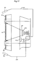
- Fig. 16 and 17 from Japanese unexamined patent publication Hei7-72817 illustrate a part of the cross-sectional diagram and the block chart of an important part for the conventional multi-vision brightness control apparatus comprising the plurality of display units.
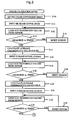
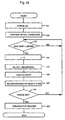
- Fig. 18 is the flow chart showing an operation of the same multi-vision brightness control apparatus.
- a screen R1 a sensor R3 for detecting the brightness of an outer rim; a wall R5; a ceiling R6; a storage shelf R7; a skylight R31; a projection unit R8; a lens block R9 of the projection unit R8; a control board R10 of the projection unit R8; a Braun tube R11 of the projection unit R8; a console panel R12 of the projection unit R8; and a lead wire R13 for transmitting signal of the sensor R3 to the control board.
- the sensor R3 is arranged at the outer rim of a screen frame, and the sensor R3 detects a beam brightness being illuminated to the screen frame. Brightness information detected by the sensor R3 is transmitted to the control board R10 via the lead wire R13, and the brightness information is stored and used for calculation for setting the brightness to the Braun tube R11.
- a content of a memory device inside a control circuit is cleared to 0, and when a certain time has lapsed, a time counter t is cleared to 0, and the sensor R3 detects a surrounding brightness, and the brightness information of the surrounding is input to the control board R10 via the lead wire R13.
- the control board R10 calculates a minimum brightness values of the Braun tube R11 so that it is easy to see responding to the surrounding brightness. A result of the calculation is inputted to the Braun tube, then brightness is set, and an image is projected to the screen. If the apparatus is turned off, a termination process is performed, and if the apparatus is not turned off, the process is repeated from the step of detecting the brightness.
- the multi-vision from the conventional example has performed the brightness control as described above. Since only information obtained from the sensor R3 is the brightness information, such that a brightness setting responding to a surrounding environment only at that instance is optimally set, and a control of the display color was not possible.
- the sensor R3 of the conventional multi-vision is not set for each one of the screens, therefore, even if there is a difference in the display colors between the screens, the conventional multi-vision is unable to detect the difference such that the color for every screen cannot be controlled, so the color is unevenly displayed as it is.
- PAJ 04 2859 92 discloses a multi-screen display device comprising means for correcting the white balance of an adjacent screen and for adjusting the contrast of the whole multi-screen display device in a reference screen display device.
- a detecting signal is inserted into an overscan part of a video signal, the detecting signal is detected by a photo detector, and taking a luminance level of a first projecting device as a reference, a luminance level of a second projecting device is corrected.
- the luminance level of the first projecting device is corrected.
- the luminance level of a third projecting device is varied.
- EP-A-0 543 332 shows a multi-vision system including a plurality of display units which comprises a sensor for performing colorimetry of display colours from the plurality of display units, a colour conversion coefficient calculation unit for calculating a colour conversion coefficient to calibrate a display colour of each display unit by using colometry values obtained from the sensor by performing the colometry for the display colours of the plurality of display units.
- the present invention aims to adjust the display color of the display unit to a target color.
- the present invention aims to get rid of the differences in the display colors between the display units by adjusting the display colors of the plurality of display units of the multi-vision system to the same target color.
- the present invention aims to improve the performance of the whole color adjustment by optimally selecting a target color which is a measure to the display color adjustment for a plurality of the display units of the multi-vision system.
- the present invention aims to perform the above-mentioned color calibration automatically eliminating too much manual operations with a simply configured unit.
- Said claim 1 refers to embodiments 1,5 iu the following.
- Embodiment 1 of the present invention is described below with reference to the drawings.
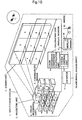
- Fig.1 shows the whole block chart of the multi-vision system comprising a color calibration function as one of the embodiments in the present invention.
- an outline 1 of the multi-vision system an outline 1 of the multi-vision system; projector units 2; and screen units 3. Note that each one of the projector units 2 are corresponding with each one of the screen units 3.
- An analog image signal inputted to an expander 9 is enlarged and divided, and image signals are generated for every one of the projector units 2.
- the image signals are inputted to the projector units 2 via color processing units 8.
- chromaticity sensors 4 are set between the screen units 3.
- the chromaticity sensors 4 are positioned so as to be able to perform colorimetry of corresponding projector units 2 for the color of the light source without color conversion by the color processing unit 8.
- a calibration unit 5 is configured from a color conversion coefficient calculation unit 7 and a system control unit 6.
- the system control unit 6 controls a series of color calibration processing by the projector units 2, the chromaticity sensors 4, the color conversion coefficient calculation unit 7, and the color processing units 8.
- the color conversion coefficient calculation unit 7 decides a target color from XYZ tristimulus values of the light source of each projector unit 2, the XYZ tristimulus values are obtained at the chromaticity sensor 4.
- the color conversion coefficient calculation unit 7 calculates a color conversion coefficient used for identifying the colors of the light source to the target color for each one of the projector units 2.
- the calculated color conversion coefficients are stored at the color processing units 8, which are corresponding to the projector units 2, one-by-one. From hereinafter, one projector unit 2 and one screen unit 3 are taken as a set, and this set concept is taken as a display.
- equation 1 shows that a color space of the display taking the additive mixture of color stimuli is a linear space.
- the equation 1 shows that the XYZ tristimulus values of X c , Y c , Z c of a color C, which is a mixture of the three primary colors R (red), G (green) and B (blue), is expressed in linear addition of the XYZ tristimulus values for each one of the three primary colors R, G and B.
- the tristimulus values of a primary color R are expressed as X r , Y r , Z r
- the tristimulus values of a primary color G are expressed as X g , Y g , Z g
- the tristimulus values of a primary color B are expressed as X b , Y b , Z b .
- X c Y c Z c X r X g X b Y r Y g Y b Z r Z g Z b ⁇ ⁇ ⁇ ⁇
- ⁇ , ⁇ , and ⁇ are scalar quantities showing an intensity of light, and these can be expressed as shown in equation 2.
- R d , G d , and B d are digital input signals of R, G and B.
- f r , f g , f b are functions that calculate the scalar quantities a, ⁇ , and ⁇ from the digital input signals of R, G and B.
- the scalar quantities ⁇ , ⁇ , and ⁇ show the intensity of light (brightness), that is, the ratio of the maximum luminous brightness for the individual primary colors, values 0 ⁇ 1.
- the XYZ tristimulus values for the color C are calculated and obtained from the digital input signals (R d , G d , B d ) that display the color C.
- the coefficients ⁇ , ⁇ , and ⁇ are the ratio of the maximum luminous brightness for the individual primary colors, and these are values between 0 to 1.
- n indicating the nth display unit.
- n is attached to a matrix of the equation 1, and the equations 3, 4 and 5 are defined as follows.
- C n X nc Y nc Z nc
- the equation 3 defines a matrix expression of the XYZ tristimulus values for the color C of the nth display.
- M n X nr X ng X nb Y nr Y ng Y nb Z nr Z ng Z nb
- the equation 4 defines a matrix expression of the XYZ tristimulus values for the three primary colors R, G and B of the nth display.
- D n ⁇ n ⁇ n ⁇ n
- the equation 5 defines a matrix expression for the ratio of the maximum luminous brightness (scalar quantities showing the intensity of light) for the individual primary colors of the nth display.
- the equation 6 is the equation 1 which are being expressed by using the matrix expressions of the equations 3, 4 and 5.
- the symbol " ⁇ " denotes a multiplication of the matrices.
- M n represents a conversion matrix, from the digital values of the input signals for R, G and B, to the XYZ tristimulus values of the color. Even if the input signals are equal, when the displayed color is different depending on a display unit, this matrix M n will be respective of each display unit.
- the color value C n expressed in the equation 6 is actually different for every display unit. Therefore, the color value C n needs to be approximately equal to a final display color by taking a correction of the signal value input to the projector unit, that is, the XYZ tristimulus values need to be approximately equal.
- the color conversion is performed at the color processing unit 8, by multiplying the input signal by the color conversion coefficient M nt , to give a color output of a common color reproduction region as shown in equation 7.
- the equation 7 multiplies the ratio for the maximum luminous brightness ratio (scalar quantities showing the intensity of light) for the individual primary colors by the color conversion coefficient M nt , for converting to a color of the common color reproduction region (a target color) .
- XYZ tristimulus values of the common color reproduction region are expressed in C t .
- C t M n • M nt • D n
- the color conversion coefficient M nt is obtained and stored in the color processing unit 8.
- M nt can easily be calculated for the three primary colors R, G and B using the equation 7.
- D n ' is the ratio of the maximum luminous brightness of separately displayed three primary colors R, G and B
- the D n ' is expressed in a unit matrix as shown in equation 8.
- the equation 8 is an expanded equation of the equation 5 showing the ratio of the maximum luminous brightness for the three primary colors R, G and B that are separately displayed.
- f r (R r ), f g (G r ), f b (B r ) is the ratio of the maximum luminous brightness for the displayed primary color R.
- f r (R g ) , f g (G g ) , f b (B g ) is the ratio of the maximum luminous brightness for the displayed primary color G.
- f r (R b ) , f g (G b ) , f b (B b ) is the ratio of the maximum luminous brightness for the displayed primary color B.
- Equation 9 is the expanded equation of the equation 7 for a case when the three primary colors R, G and B are separately displayed, as in the case of the equation 8.
- the M n -1 in the equation 10 shows an inverse matrix of M n .
- the equation 10 calculates the color conversion coefficient M nt which needs to be calculated in the end.
- the color calibration in the present system is to obtain the color conversion coefficients M nt in the color processing unit.
- a method of the color calibration executed by the system control unit 6 will be described with reference to Figs.2 and 3 .
- the system control unit 6 sets no color conversion mode to each color processing unit 8 (S10) .
- black (BK) is displayed first on the screen, and the primary colors R, G and B are displayed in this order.
- the reason for displaying black (BK) is because a black drifting phenomena must be taken into account, and there is no need to display black (BK) if there is no need to take account of the black drifting phenomena.
- the input signal values (R d , G d , B d ) for all the colors are;
- black (BK) is displayed to the display units all at the same time, and all of XYZ tristimulus values obtained from the chromaticity sensors 4 of the display units are - transferred to the color conversion coefficient calculation unit 7.
- the color conversion coefficient calculation unit 7 a plurality of XYZ tristimulus values from a several number of measurements by the sensors are stored, and after completing the measurements for m times, an average value of XYZ tristimulus values for each one of the display units is calculated for every display units (S11 ⁇ S15). The calculated value is used when taking into account the black drifting phenomena which will be described later.
- the target color is set at the color conversion coefficient calculation unit 7 (S50).
- the XYZ tristimulus values with a smallest chroma is set as XYZ tristimulus values of the target color C t .
- the method of deciding the colorimetry value with the smallest chroma is to measure the distances between the points and the achromatic axis which is expressed in a straight line, in a 3-dimensional XYZ space, and the point with a shortest distance is selected as the colorimetry value.
- the projection into the 2-dimensional plane is expressed by converting to x, y chromaticity coordinate shown in the equation 11.
- XYZ tristimulus values of the representing color (primary color) R for the display unit n is expressed in (X nr , Y nr , Z nr ), when this value is expressed in the chromaticity coordinate (x nr , y nr , z nr ), the result is shown below in equation 11.
- the achromatic axis becomes one of the points, and expressed in 2 variables.
- the value with the smallest chroma in the colorimetry values is the colorimetry value with the shortest distance from the achromatic point.
- Y value is chosen and set from the XYZ tristimulus values.
- Y nr from the (x nr , y nr ) of the display n which is calculated to be the smallest one from the equation 12, is adopted as it is, and then values of X nr , Z nr are calculated.
- This process is similarly performed for the primary colors G and B, to obtain the XYZ tristimulus values (X tg , Y tg , Z tg ) and (X tb , Y tb , Z tb ) for the target colors of the two primary colors.
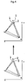
- These XYZ tristimulus values are difficult to display in the 3-dimensional space, therefore, for the purpose of simplicity, the result when displaying these in the 2-dimensional x, y chromaticity diagram is shown in Fig.4 .
- Fig.4 illustrates an example using three display units, and a diagram on left shows the result of colorimetry, and the diagram on right shows the chromaticity coordinate of the decided target colors in black dots " ⁇ ".
- the black dot ⁇ shows that R3 having the smallest chroma is chosen from the colorimetry values R1, R2 and R3 as the target color of the chromataicity coordinate.
- Another method of setting the target color is available as described below. From the XYZ tristimulus values of the colorimetry result for all of the n number of the display units, an average value (i.e. center of gravity) for all the representing colors are calculated, and the calculated value is set as the XYZ tristimulus values of the target color. For example, provided that the XYZ tristimulus values of the representing color R for the display unit n is expressed in (X nr , Y nr , Z nr ), the XYZ tristimulus values of the target color for the primary color R (X tr , Y tr , Z tr ) is shown in equation 13.
- the equation 13 calculates the average value (i.e. center of gravity) of all the XYZ tristimulus values of the representing color R for the display unit.
- Fig.5 shows the result of displaying these in the 2-dimensional x, y chromaticity diagram.
- Fig.5 illustrates an example of the three display units, for which the diagram on left shows the colorimetry result and the diagram on right shows the chromaticity coordinate of the decided target colors in black dots " ⁇ ".
- the black dot ⁇ on R shows the average value (center of gravity) of the colorimetry values R1, R2 and R3.
- the color conversion coefficients M nt are calculated based on each projector unit (S51) .
- the equation 14 is the equation 1 which shows the XYZ tristimulus values of the color C when taking into account the effect of black drifting due to the dark current. That is, the XYZ tristimulus values X c , Y c , Z c of the color C which are the color obtained from a mixture of the three primary colors R, G and B, are linear addition of subtracted values of the XYZ tristimulus values X k , Y k , Z k of the dark current from the XYZ tristimulus values of the three primary colors.
- ⁇ , ⁇ and ⁇ are expressed as shown in equation 15.
- R d , G d , B d are the digital input signals of R, G and B in 8 bits.
- Y (R d ) , Y (G d ) , Y (B d ) are the luminous brightness for individual primary colors when taken into account the effect of the black drifting by the dark current.
- Y k is the luminous brightness by the dark current when displaying black (BK) .
- Y r , Y g , Y b are the maximum luminous brightness for individual primary colors.
- the equation 15 supposes that the optical device having the functions f r , f g ,f b of the equation 2 being expressed in the linear function.
- the equation 16 is for calculating the luminous brightness Y (R d ) , Y (G d ) , Y (B d ) of the individual primary colors when the effect of the black drifting due to the dark current is taken into account. Therefore, the equation 15 calculates the scalar quantities ⁇ , ⁇ and ⁇ (the ratio of the maximum luminous brightness of the individual primary colors) which express the intensity of light from the digital input signals of R, G and B when the luminous brightness Y (R d ) , Y (G d ) , Y (B d ) of the individual primary colors calculated from the equation 16 are used upon taking into account the effect of the black drifting due to the dark current.
- equation 15 is expressed as equation 17.
- the equation 17 express the scalar quantities ⁇ , ⁇ and ⁇ (the ratio of the maximum luminous brightness for the individual primary colors) which shows the intensity of light for the case of the CRT monitor or the projector when the luminous brightness cannot be calculated using the linear function.
- the equations 15, 16 and 17 are for describing ⁇ , ⁇ and ⁇ in the equation 14.
- the ⁇ , ⁇ and ⁇ are expressed in the equation 15, as mentioned after the equation 2, "to normalize the input signals ranging from digital values 0 ⁇ 255, the input signals are simply divided by 255 and the coefficients ⁇ , ⁇ and ⁇ are calculated". In this way, the equation 10 is reached via the equations 8 and 9.
- the conversion matrix M n is defined in equation 18.
- the XYZ tristimulus values of the target color C t is defined in equation 19.
- the equation 18 defines the equation 4 that takes into account the effect of black drifting due to the dark current, that is, it defines the matrix expression of the XYZ tristimulus values of the three primary colors R, G and B of the nth display.
- X nk , Y nk , Z nk of the equation 18 are the XYZ tristimulus values for the case of displaying black (BK) to the nth display.
- the equation 19 defines the equation 9 that takes into account the effect of black drifting due to the dark current, that is, it defines the matrix expression of the XYZ tristimulus values of the three primary colors R, G and B.
- X tk , Y tk , Z tk of the equation 19 is the XYZ tristimulus values of black of the target color.
- the XYZ tristimulus values (X tk , Y tk , Z tk ) of black of the target color from the XYZ tristimulus values (X nk , Y nk , Z nk ) of the target color black for each display unit, the XYZ tristimulus values with a largest Y nk is selected.
- the D n ' -1 is the inverse matrix of the matrix D n .
- the calculated color conversion coefficient M nt of the display unit is stored in the color processing unit 8 (S52), and a test image is displayed (S53) and then the color calibration mode is completed.
- the color calibration is executed. Also, in the present embodiment, by performing colorimetry of the displaying color from the plurality of display units, the target color is automatically calculated.
- the multi-vision system installs the chromaticity sensors for performing colorimetry of the plurality of display units, places the chromaticity sensors at the non-display area which is in between the plurality of the display units, and performs colorimetry of the light directly from the light source, therefore, the system enables to achieve the color calibration device without making the device too large in scale.
- the colorimetry value with the smallest chroma from the colorimetry values in the plurality of display units is chosen as the target color of the representing color, the target color is automatically set, a strict color calibration is automatically performed from a viewpoint of the chroma, therefore, problem of narrowing down of the color-reproduction region when just seeking for the common color reproduction region is solved.
- the average value of the colorimetry values from the plurality of display units is taken as the target color for the representing color, so that the target color is automatically set for automatic color calibration, therefore, problem of narrowing down of the color reproduction region when just seeking for the common color reproduction region is solved.
- this embodiment when a target color is set beforehand, this embodiment can be applied to the color calibration having a single display unit.
- the example is characterized by the color conversion coefficient calculation unit 7 which calculates the color conversion coefficient using the 3-dimensional space. That is, the example is characterized in calculating the color conversion coefficient using the XYZ tristimulus values for the color obtained by mixing the three primary colors based on the additive mixture of color stimuli model.
- Embodiment 2 of the present invention will be described with reference to the drawing.
- Fig.6 is the whole block chart of the multi-vision system provided with the color calibration function, showing one of the embodiments in the present invention.
- embodiment 2 being different from embodiment 1 is that the positions of the chromaticity sensors 4 are outside of the multi-vision system, as illustrated in Fig.6 .
- the sensor of the embodiment 2 does not perform colorimetry of the light source, but it performs colorimetry for the colors of the screen unit 3.
- the sensor in embodiment 1 is measuring a light leaking to outside of the screen, however, in the system of embodiment 2, a color at the screen center is measured by the sensor.
- the method of calibration is same as embodiment 1.
- the chromaticity sensors which perform colorimetry of the plurality of the display units, are placed outside of the multi-vision system, therefore, the sensors does not perform colorimetry for the light from the light source, but perform colorimetry for the display colors of the display units. And further, the positions where the colorimetry should take place can be set-to the central parts of the display units, for this reason, an accurate colorimetry which further leads to an accurate color calibration becomes possible.
- Fig.7 is the whole block chart of the multi-vision system provided with the color calibration function, showing one of the embodiments in the present invention.
- embodiment 3 being different from embodiment 1 is that a smaller number of chromaticity sensors 4 than the number of display units are placed outside of the multi-vision system, as illustrated in Fig.7 .
- These chromaticity sensors 4 are arranged in a line on top a sensor unit 10.
- the number of chromaticity sensors 4 in the sensor unit 10 are same as the number of the display units that are aligned horizontally in one line.
- the sensor unit 10 is provided with a mechanism that scans in parallel to multi-vision, which is a direction A (the mechanism not illustrated). While the sensor unit 10 scans the multi-vision in up and down directions, the sensor unit 10 performs colorimetry at a plurality of points for each screen unit. The colorimetry points in each screen unit 3 are shown in "x" in Fig.7 .
- the figure illustrates four colorimetry points for each screen unit 3, however, the points can be more or less than this.
- the average value is calculated from the XYZ tristimulus values of the representing color for each screen unit 3 (S67). Same processing are done at middle and lowermost levels, and then the colorimetry for all screen units 3 are completed (S71 ⁇ S77, S81 ⁇ S87). All the processing afterwards such as calculation of the target color and calculation of the color conversion coefficient are same as in embodiment 1 (S50 ⁇ S53).
- the chromaticity sensors for performing colorimetry of the colors of the plurality of display units are aligned in the sensor unit outside the multi-vision system, and the sensor unit scans the multi-vision in parallel to perform colorimetry of the display colors for all the display units, therefore, colorimetry of all display units using a less number of chromaticity sensors becomes possible.
- the scanning direction by the sensors illustrated is only 1-dimensional in the direction of A, however, 2-dimensional scanning can also be performed by installing the scanning mechanism in parallel to the multi-vision and in a direction 90 degrees to the direction A.
- the colorimetry values of all colorimetry points are being averaged out.
- a position of the colorimetry point is freely decided in the screen unit, and the one point only may be used as the colorimetry value.
- an averaged value of the plurality of the arbitrary colorimetry points may be used.
- Embodiment 4 of the present invention is described with reference to the drawings.
- Fig.10 is the whole block chart of the multi-vision system provided with the color calibration function, showing one of the embodiments in the present invention.
- embodiment 4 being different from embodiment 1 is, that the colorimetry values (XYZ tristimulus values) of the primary colors BK, R, G and B for each screen unit 3 are displayed in 3-dimensional coordinates 20 of a display monitor 11 connected to the system control unit 6 upon setting the target colors, as illustrated in Fig.10 .
- An operator can recognize colorimetry results for each screen unit 3 from the display monitor 11, and the operator can set the target color of each primary color using a pointing device such as mouse 12.
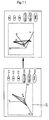
- a method of setting the target color is described with reference to Fig.11 .
- Fig. 11 illustrates two of the screens of the display monitor 11 connected to the system control unit 6.
- the screen on the left illustrates a status prior to deciding the target color
- the screen on the right illustrate a status after the target color has been decided.
- the colorimetry results for each screen unit are illustrated on the 3-dimensional coordinates 20.
- the 3-dimensional coordinates can rotate.
- Fig.11 for the purpose of simplifying the drawing, the colorimetry results from the two screen units are being displayed.
- the operator can see the colorimetry results on the 3-dimensional coordinates 20, when setting the target color to have a maximum common color reproduction region for all the screen units, for example.
- a button R is clicked using the mouse 12
- a letter R and a black dot " ⁇ " appears on the 3-dimensional coordinates 20.
- the operator can drag the black dot " ⁇ " on the 3-dimensional coordinates 20.
- a rotate button 26 is clicked using the mouse 12, so that the coordinate system will rotate.
- a several display patterns of the coordinate system are available, and every time the rotate button is clicked, the displayed coordinate system is changed to a next display pattern.
- a limitation can be installed so that the XYZ tristimulus values of the target color is set only on sides and apexes of triangles formed by connecting three colorimetry values of the representing colors for each screen unit.
- the target color is decided for R as a coordinate value of the black dot " ⁇ ".
- the target color is decided in the same manner for G and B, and when the end button is clicked, a triangle will be displayed with apexes indicating the XYZ tristimulus values of the target color, and the operator can recognize the target color that has been decided. This situation is illustrated on the right hand side of Fig.11 . All other processing such as calculation of the color conversion coefficient is same as embodiment 1.
- the target color is also decided automatically.
- the target color in the color reproduction region for all the display units, is set so that the common color reproduction region can be maximum, such that the target color can be displayed by all the display units, and a strict color calibration becomes possible this way.
- the operator recognizes the colorimetry results for all the display units appearing on the attached display monitor and decides the target color, therefore, the common color reproduction region for most of the display units can be set to the maximum simply by looking into the monitor.
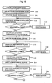
- Embodiment 5 of the present invention is described with reference to the drawings.
- Fig.12 is the whole block chart of the multi-vision system provided with the color calibration function, showing one of the embodiments in the present invention.
- the characteristic of the present invention being different from embodiment 1 is that the XYZ tristimulus values of the previous colorimetry is referred for a calibration from two times when setting the target color, and if there is a large difference between the present XYZ tristimulus values and the previous tristimulus values, then the calibration is executed.
- Figs.13 and 14 are same as Figs.2 and 3 .
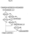
- the decision of whether to execute calibration or not in step S46 is done prior to the calculation of the target color (S50). A specific content of this decision is described according to the flow chart of Fig.15 .
- M n1 a matrix taking into account the black drifting is expressed in equation 20 as M n1 .
- M n ⁇ 1 X nrl - X nkl X ngl - X nkl X nbl - X nkl Y nrl - Y nkl Y ngl - Y nkl Y nbl - Y nkl Z nrl - Z nkl Z ngl - Z nkl Z nbl - Z nkl
- the equation 20 defines a matrix expression of the XYZ tristimulus values of the three primary colors R, G and B for a previous nth display, taking into account the black drifting due to the dark current.
- C tl X trl - X tkl X tgl - X tkl X tbl - X tkl Y trl - Y tkl Y tgl - Y tkl Y tbl - Y tkl Z trl - Z tkl Z tgl - Z tkl Z tbl - Z tkl
- the equation 21 defines a matrix expression of XYZ tristimulus values of the target color from the previous three primary colors R, G and B for the case of taking into account the black drifting due to the dark current.
- the matrix M n that takes into account the black drifting of the XYZ tristimulus values of the primary colors for the present colorimetry is expressed in the equation 18, and the target color C t is expressed in the equation 19.
- M n1 -M n is calculated from the previous colorimetry value and the present colorimetry value, and the calculated value D Mn is expressed in equation 22.
- the equation 22 defines a difference of M n1 calculated from the previous colorimetry result of the equation 20 and M n calculated from the present colorimetry result of the equation 18.
- Decision 1 decides whether the following condition is met "in all display units there are no absolute value of element of matrix D Mn which exceeds a threshold value th1". Equation 23 expresses this condition. dn ij ⁇ thl
- the equation 23 shows that the absolute value of element of matrix D Mn is smaller than a threshold value th1.
- Decision 2 decides whether the following condition is met "for all display units, calculate addition of the absolute value of elements of matrix D Mn as a decision parameter P1 and the decision parameter P1 does not exceed a threshold value th2". Equation 24 expresses this condition.
- P ⁇ 1 ⁇ i ⁇ j dn ij ⁇ th ⁇ 2
- the equation 24 shows that the addition of the absolute values of elements of matrix D Mn " is smaller than the threshold value th2.
- Decision 4 decides whether the following condition is met "a number of display units that did not meet the equation 24 do not exceed a threshold value th4". When there are more display units that did not meet the equation 24, that is, when there are more display units that had change to a certain extent, calibration is executed as normal.
- the equation 25 defines a difference of the XYZ tristimulus values of matrix C t1 for the previous target color (equation 21) and the present colorimetry result M n (equation 18).
- Decision 5 decides whether the following condition is met "for all display units, calculate addition of absolute value of elements of matrix D Cn factor as a decision parameter P2, and the decision parameter P2 does not exceed a threshold value th5". This is specifically expressed in the equation below.
- P ⁇ 2 ⁇ i ⁇ j cn ij ⁇ th ⁇ 5
- the equation 26 shows that the addition of the absolute values of elements of matrix D Cn of the equation 25 is smaller than the threshold value th5.
- color calibration is executed to display units other than the display units that have met all of the equations 23, 24 and 26. At this time, the color conversion coefficient is calculated using the previous value C t1 as the target color.
- a colorimetry value of each display unit and a chromaticity value of the target color is stored in the memory, and a next colorimetry value obtained for the next calibration is compared with a previous colorimetry value, or with the chromaticity value of the target color, then only when there is a difference to a certain extent between the compared values the calibration is executed, such that an unnecessary processing is not involved.
- a colorimetry value of each display unit and a chromaticity value of the target color are stored in the memory, and a next colorimetry value obtained for the next calibration is compared with a previous colorimetry value, or with the chromaticity value of the target color, and the display unit with a difference in the compared values to a certain extent is selected automatically, and only for the selected display unit the color calibration is performed, such that unnecessary processing is not involved.
- the present invention combines all three properties of the color (lightness/chroma/hue), however, the disclosed content of Japanese unexamined patent publication sho63-2613276 is an adjustment of the hue only.
- the present invention develops the color calibration for the multi-vision comprising a plurality of the display units so that the target color is set automatically, however, the disclosed content of Japanese unexamined patent publication sho63-261327 is the color adjustment for a single display unit only.
- the present invention performs colorimetry for the representing color displayed in a display unit without the color conversion, calculates the color conversion coefficients so that the color of the display unit will be the target color, and stores to the color processing unit, therefore, the color calibration is automatically performed, as a result, the display unit can convert and display the aiming target color or the color close to the target color.
- the representing colors are displayed on the plurality of the display units without the color-conversion.
- the color conversion coefficient is calculated from the colorimetry results so that the representing colors of the display units will be the target color, and is stored to the color processing units, therefore, the color calibration is automatically performed, and as a result, the plurality of the display units can convert color and can display the aiming target color or the color close to the target color.
- the sensors are installed inside the multi-vision such that the color calibration device is implemented without making the device large more than necessary and at a low cost.
- the sensors are placed outside of the multi-vision, therefore, it can perform colorimetry for the color of the display units and not the light source, and further the position for colorimetry can be set to the central part of the display units, such that the accurate colorimetry which leads to the accurate color calibration becomes possible.
- the sensors are placed outside of the multi-vision to scan the multi-vision in parallel, therefore, colorimetry of all the display units using a smaller number of sensors than the number of the display units becomes possible, such that the cost can be reduced.
- the colorimetry point of single display unit can be shifted for performing colorimetry, so that when taking the average value of the colorimetry values, it becomes possible to correct an unbalance in the single display unit, and the color calibration can be performed by focusing on the arbitrary point.
- the aiming target color is decided from the colorimetry results of all the display units so that the common color reproduction region of all the display units are set to maximum, and because the target color is the color which can be displayed by all the display units, a strict color calibration will become possible.
- the aiming target color is decided by the operator recognizing the colorimetry results of all the display units displayed on the attached display monitor, therefore, setting the common color reproduction region of most display units are visually set to maximum.
- the colorimetry value with a smallest chroma is automatically set from the colorimetry results of all display units, therefore, from a viewpoint of chroma, a strict color calibration is automatically performed, and problem of narrowing down of the color reproduction region when simply seeking for the common color reproduction region is solved.
- the average value (center of gravity) of the colorimetry values for all display units are automatically calculated from the colorimetry results of all display units, and aiming target color is set this way, therefore, the color calibration is performed automatically such that the problem of narrowing down of the color reproduction region when simply seeking for the common color reproduction region is solved.
- the colorimetry results of all display units and the XYZ tristimulus values of the target color are stored in the memory, and by comparing with the next colorimetry results, calibration is executed only when the calibration need to be executed such that unnecessary processing is not involved.
- the colorimetry results of all display units and the XYZ tristimulus values of the target color are stored in the memory, and by comparing with the next colorimetry results, calibration is executed for the display units that need to be executed such that unnecessary processing is not involved.
Landscapes
- Engineering & Computer Science (AREA)
- Multimedia (AREA)
- Signal Processing (AREA)
- Health & Medical Sciences (AREA)
- Biomedical Technology (AREA)
- General Health & Medical Sciences (AREA)
- Controls And Circuits For Display Device (AREA)
- Processing Of Color Television Signals (AREA)
- Video Image Reproduction Devices For Color Tv Systems (AREA)
Abstract
Claims (1)
- Système multivision (1) comprenant une pluralité d'unités d'affichage (3), doté d'une fonction d'étalonnage de couleur destinée à régler une couleur d'affichage de chaque unité d'affichage, comprenant :une pluralité de capteurs (4) destinés à exécuter une colorimétrie des couleurs d'affichage de la pluralité d'unités d'affichage (3) ;une unité de calcul de coefficient de conversion de couleur (7) destinée à calculer un coefficient de conversion de couleur de façon à étalonner une couleur d'affichage de chaque unité d'affichage (3) en utilisant les valeurs de colorimétrie obtenues en provenance du capteur (4) en exécutant la colorimétrie des couleurs d'affichage de la pluralité d'unités d'affichage (3) ;une unité de traitement de couleur (8) destinée à exécuter une conversion de couleur de la couleur d'affichage de chaque unité d'affichage (3) en utilisant un coefficient de conversion de couleur calculé à partir de l'unité de calcul de coefficient de conversion de couleur (7) ;dans lequel l'unité de traitement de couleur (8) reçoit un signal de chacune des couleurs primaires R, G et B, et du noir, et affiche chaque couleur sur les unités d'affichage (3) sans conversion de couleur ;dans lequel le capteur (4) exécute une colorimétrie de la couleur représentative de la pluralité d'unités d'affichage (3) affichée par l'unité de traitement de couleur (8) ; etdans lequel l'unité de calcul de coefficient de conversion de couleur (7) calcule le coefficient de conversion de couleur de chaque unité d'affichage (3) de façon à effectuer une conversion de couleur de la couleur primaire mesurée par le capteur (4) en une couleur cible prédéterminée, et délivre en sortie un coefficient de conversion de couleur calculé à l'unité de traitement de couleur (8) ; et une mémoire (13) destinée à stocker des composantes trichromatiques XYZ de la couleur cible et une valeur de colorimétrie d'un étalonnage précédent de chaque unité d'affichage (3) ;dans lequel, si, en tant que première condition, pour toutes les unités d'affichage (3) il n'y a pas de valeur absolue des éléments d'une matrice DMn qui dépasse une première valeur de seuil, dans laquelle DMn est définie en tant que :est une expression matricielle des composantes trichromatiques XYZ des couleurs primaires d'un affichage précédent d'une n-ième unité d'affichage (3), prenent en compte la dérivée du noir au courant d'obscurité, et

où

est une expression matricielle des composantes trichromatiques XYZ des couleurs primaires de l'affichage en cours d'une n-ième unité d'affichage (3), prenant en compte la dérive du noir due au courant d'obscurité,
et si, en tant que deuxième condition pour toutes les unités d'affichage (3), la somme des valeurs absolues des éléments de la matrice DMn ne dépasse pas une deuxième valeur de seuil, l'étalonnage de couleur n'est pas exécuté ;
si la condition 1 est remplie et si la condition 2 n'est pas remplie, si, en tant que troisième condition, pour un certain nombre d'unités d'affichage (3), la somme des valeurs absolues des éléments de la matrice DMn ne dépasse pas une troisième valeur de seuil, et si, en tant que quatrième condition, pour toutes les unités d'affichage (3), la somme des valeurs absolues des éléments d'une matrice DCn ne dépasse pas une quatrième valeur de seuil, où DCn est définie en tant que :
où
est une expression matricielle des composantes trichromatiques XYZ pour les valeurs cibles précédentes des couleurs primaires de l'affichage précédent de la n-ième unité d'affichage (3), prenant en compte la dérive du noir due au courant d'obscurité, l'étalonnage de couleur est exécuté pour les unités d'affichage autres que les unités d'affichage qui ont rempli toutes les conditions ci-dessus ; et.a) si la condition 1 n'est pas remplie et si, en tant que cinquième condition, pour un certain nombre d'unités d'affichage (3), il n'y a aucune valeur absolue des éléments de la matrice DMn qui ne dépasse pas une cinquiéme valeur de seuil; oub) si la condition 1 est remplie, si la condition 2 n'est pas remplie ou si la condition 5 est remplie, et si la condition 3 n'est pas remplie ; ouc) si la condition 1 est remplie, si la condition 2 n'est pas remplie ou si la condition 5 est remplie, et si la condition 3 est remplie, et si la condition 4 n'est pas remplie ;un étalonnage de couleur est exécuté vers toutes les unités d'affichage (3).
Applications Claiming Priority (1)
| Application Number | Priority Date | Filing Date | Title |
|---|---|---|---|
| PCT/JP1998/001709 WO1999053693A1 (fr) | 1998-04-15 | 1998-04-15 | Systeme multivision, procede d'etalonnage de couleurs et visualisation |
Publications (3)
| Publication Number | Publication Date |
|---|---|
| EP0989757A1 EP0989757A1 (fr) | 2000-03-29 |
| EP0989757A4 EP0989757A4 (fr) | 2000-03-29 |
| EP0989757B1 true EP0989757B1 (fr) | 2011-12-07 |
Family
ID=14208049
Family Applications (1)
| Application Number | Title | Priority Date | Filing Date |
|---|---|---|---|
| EP98914018A Expired - Lifetime EP0989757B1 (fr) | 1998-04-15 | 1998-04-15 | Systeme multivision, procede d'etalonnage de couleurs et visualisation |
Country Status (4)
| Country | Link |
|---|---|
| US (1) | US6340976B1 (fr) |
| EP (1) | EP0989757B1 (fr) |
| JP (1) | JP3514776B2 (fr) |
| WO (1) | WO1999053693A1 (fr) |
Cited By (1)
| Publication number | Priority date | Publication date | Assignee | Title |
|---|---|---|---|---|
| CN103050109A (zh) * | 2012-12-25 | 2013-04-17 | 广东威创视讯科技股份有限公司 | 多屏显示装置颜色校正方法和系统 |
Families Citing this family (80)
| Publication number | Priority date | Publication date | Assignee | Title |
|---|---|---|---|---|
| US6483537B1 (en) | 1997-05-21 | 2002-11-19 | Metavision Corporation | Apparatus and method for analyzing projected images, singly and for array projection applications |
| JP2000338950A (ja) * | 1999-05-26 | 2000-12-08 | Olympus Optical Co Ltd | 色再現システム |
| JP2001056658A (ja) * | 1999-06-07 | 2001-02-27 | Sony Corp | 陰極線管並びに輝度制御装置および方法 |
| WO2002019028A1 (fr) * | 2000-06-13 | 2002-03-07 | Panoram Technologies, Inc. | Procede et appareil permettant une integration continue de multiples projecteurs video |
| US7002606B2 (en) | 2000-07-17 | 2006-02-21 | Matsushita Electric Industrial Co., Ltd. | Image signal processing apparatus, image display apparatus, multidisplay apparatus, and chromaticity adjustment method for use in the multidisplay apparatus |
| EP1185110B1 (fr) * | 2000-08-31 | 2010-02-10 | Texas Instruments Incorporated | Adaptation automatique de la couleur pour un système de projection à ecrans juxtaposés |
| KR100396683B1 (ko) * | 2001-01-08 | 2003-09-03 | 엘지전자 주식회사 | 티브이의 화면밝기/색도 보정장치 및 방법 |
| JP2002278537A (ja) * | 2001-03-22 | 2002-09-27 | Canon Inc | 画像処理装置、および、画像処理方法 |
| US6677958B2 (en) * | 2001-06-22 | 2004-01-13 | Eastman Kodak Company | Method for calibrating, characterizing and driving a color flat panel display |
| US7460179B2 (en) * | 2002-01-31 | 2008-12-02 | Hewlett-Packard Development Company, L.P. | Adaptive image display |
| US7391475B2 (en) | 2002-01-31 | 2008-06-24 | Hewlett-Packard Development Company, L.P. | Display image generation with differential illumination |
| US7283181B2 (en) * | 2002-01-31 | 2007-10-16 | Hewlett-Packard Development Company, L.P. | Selectable color adjustment for image display |
| FR2837056B1 (fr) * | 2002-03-07 | 2004-09-17 | France Telecom | Procede et systeme d'uniformisation du rendu colorimetrique d'une juxtaposition de surfaces d'affichage |
| KR20040013957A (ko) * | 2002-08-09 | 2004-02-14 | 엘지전자 주식회사 | 멀티비전 및 그 화면 구현 방법 |
| US7215362B2 (en) * | 2002-10-31 | 2007-05-08 | Fraunhofer-Gesellschaft Zur Foerderung Der Angewandten Forschung E.V. | Auto-calibration of multi-projector systems |
| JP4126487B2 (ja) * | 2002-11-08 | 2008-07-30 | 株式会社沖データ | 画像変換方法および画像変換装置 |
| US7184054B2 (en) * | 2003-01-21 | 2007-02-27 | Hewlett-Packard Development Company, L.P. | Correction of a projected image based on a reflected image |
| US7187797B2 (en) * | 2003-04-01 | 2007-03-06 | Applied Vision Company, Llc | Color machine vision system for colorimetry |
| US20040196250A1 (en) * | 2003-04-07 | 2004-10-07 | Rajiv Mehrotra | System and method for automatic calibration of a display device |
| TWI249959B (en) * | 2003-05-16 | 2006-02-21 | Seiko Epson Corp | Image processing system, projector, information memorizing medium and image processing method |
| JP3790928B2 (ja) * | 2003-06-27 | 2006-06-28 | オリンパス株式会社 | 画像表示装置における補正データ取得方法およびキャリブレーションシステム |
| US7688316B2 (en) * | 2003-08-12 | 2010-03-30 | Apple Inc. | Adaptive method for acquiring color measurements |
| CN100533543C (zh) * | 2003-12-12 | 2009-08-26 | 松下电器产业株式会社 | 彩色图像显示装置、色变换装置、色彩模拟装置及方法 |
| US7365720B2 (en) * | 2003-12-23 | 2008-04-29 | Barco N.V. | Colour calibration of emissive display devices |
| US7834819B2 (en) | 2004-04-01 | 2010-11-16 | Polyvision Corporation | Virtual flip chart method and apparatus |
| US7948448B2 (en) | 2004-04-01 | 2011-05-24 | Polyvision Corporation | Portable presentation system and methods for use therewith |
| US7253841B2 (en) * | 2004-04-07 | 2007-08-07 | National Applied Research Laboratories | Remote control method of tile display |
| US7394937B2 (en) | 2004-05-19 | 2008-07-01 | Applied Vision Company, Llc | Vision system and method for process monitoring |
| US7313270B2 (en) * | 2004-05-19 | 2007-12-25 | Applied Vision Company, Llc | Vision system and method for process monitoring |
| US7673995B2 (en) | 2004-07-06 | 2010-03-09 | Northrop Grumman Corporation | System and method for projector alignment |
| JP2006058754A (ja) * | 2004-08-23 | 2006-03-02 | Canon Inc | 表示装置 |
| US20060181552A1 (en) * | 2005-02-11 | 2006-08-17 | Siemens Medical Solutions Usa, Inc. | Image display calibration for ultrasound and other systems |
| TW200701179A (en) * | 2005-06-17 | 2007-01-01 | Mitac Technology Corp | Method of adjusting brightness and system using the same |
| US20070091434A1 (en) * | 2005-10-21 | 2007-04-26 | Hewlett-Packard Development Company, L.P. | Luminance adjustment |
| US8130184B2 (en) * | 2005-10-21 | 2012-03-06 | Hewlett-Packard Development Company L. P. | Image pixel transformation |
| US20070091435A1 (en) * | 2005-10-21 | 2007-04-26 | Hewlett-Packard Development Company, L.P. | Image pixel transformation |
| US7609444B2 (en) * | 2005-10-21 | 2009-10-27 | Hewlett-Packard Development Company, L.P. | Projection partitioning and aligning |
| JP4823660B2 (ja) * | 2005-11-25 | 2011-11-24 | 三菱電機株式会社 | マルチ画面表示装置 |
| US8248454B2 (en) * | 2007-11-14 | 2012-08-21 | Hewlett-Packard Development Company, L.P. | Video display calibration system and method |
| US20090184947A1 (en) * | 2008-01-22 | 2009-07-23 | Hupman Paul M | Color calibration system and method |
| DE102008019726A1 (de) * | 2008-04-18 | 2009-10-22 | Zentrum für Bild- und Signalverarbeitung e.V. | Verfahren und Vorrichtung zur Farbkalibrierung von Projektoren |
| CA2722132C (fr) * | 2008-05-02 | 2017-03-28 | Thomson Licensing | Procede, appareil et systeme pour une gestion automatique de la couleur dans le domaine du cinema numerique |
| US8608321B2 (en) * | 2008-06-17 | 2013-12-17 | The Invention Science Fund I, Llc | Systems and methods for projecting in response to conformation |
| US20090310039A1 (en) * | 2008-06-17 | 2009-12-17 | Searete Llc, A Limited Liability Corporation Of The State Of Delaware | Methods and systems for user parameter responsive projection |
| US8641203B2 (en) * | 2008-06-17 | 2014-02-04 | The Invention Science Fund I, Llc | Methods and systems for receiving and transmitting signals between server and projector apparatuses |
| US20110176119A1 (en) * | 2008-06-17 | 2011-07-21 | Searete Llc, A Limited Liability Corporation Of The State Of Delaware | Methods and systems for projecting in response to conformation |
| US8267526B2 (en) * | 2008-06-17 | 2012-09-18 | The Invention Science Fund I, Llc | Methods associated with receiving and transmitting information related to projection |
| US8430515B2 (en) * | 2008-06-17 | 2013-04-30 | The Invention Science Fund I, Llc | Systems and methods for projecting |
| US8540381B2 (en) * | 2008-06-17 | 2013-09-24 | The Invention Science Fund I, Llc | Systems and methods for receiving information associated with projecting |
| US20100066983A1 (en) * | 2008-06-17 | 2010-03-18 | Jun Edward K Y | Methods and systems related to a projection surface |
| US20100066689A1 (en) * | 2008-06-17 | 2010-03-18 | Jung Edward K Y | Devices related to projection input surfaces |
| US20090309826A1 (en) * | 2008-06-17 | 2009-12-17 | Searete Llc, A Limited Liability Corporation Of The State Of Delaware | Systems and devices |
| US20090313153A1 (en) * | 2008-06-17 | 2009-12-17 | Searete Llc, A Limited Liability Corporation Of The State Of Delaware. | Systems associated with projection system billing |
| US20090310103A1 (en) * | 2008-06-17 | 2009-12-17 | Searete Llc, A Limited Liability Corporation Of The State Of Delaware | Methods and systems for receiving information associated with the coordinated use of two or more user responsive projectors |
| US8733952B2 (en) * | 2008-06-17 | 2014-05-27 | The Invention Science Fund I, Llc | Methods and systems for coordinated use of two or more user responsive projectors |
| US20090309828A1 (en) * | 2008-06-17 | 2009-12-17 | Searete Llc, A Limited Liability Corporation Of The State Of Delaware | Methods and systems for transmitting instructions associated with user parameter responsive projection |
| US20090310098A1 (en) * | 2008-06-17 | 2009-12-17 | Searete Llc, A Limited Liability Corporation Of The State Of Delaware | Methods and systems for projecting in response to conformation |
| US8723787B2 (en) * | 2008-06-17 | 2014-05-13 | The Invention Science Fund I, Llc | Methods and systems related to an image capture projection surface |
| US8384005B2 (en) * | 2008-06-17 | 2013-02-26 | The Invention Science Fund I, Llc | Systems and methods for selectively projecting information in response to at least one specified motion associated with pressure applied to at least one projection surface |
| US8820939B2 (en) | 2008-06-17 | 2014-09-02 | The Invention Science Fund I, Llc | Projection associated methods and systems |
| US8944608B2 (en) * | 2008-06-17 | 2015-02-03 | The Invention Science Fund I, Llc | Systems and methods associated with projecting in response to conformation |
| US20090310038A1 (en) * | 2008-06-17 | 2009-12-17 | Searete Llc, A Limited Liability Corporation Of The State Of Delaware | Projection in response to position |
| US20090313152A1 (en) * | 2008-06-17 | 2009-12-17 | Searete Llc, A Limited Liability Corporation Of The State Of Delaware | Systems associated with projection billing |
| US20090312854A1 (en) * | 2008-06-17 | 2009-12-17 | Searete Llc, A Limited Liability Corporation Of The State Of Delaware | Methods and systems for transmitting information associated with the coordinated use of two or more user responsive projectors |
| US20090313151A1 (en) * | 2008-06-17 | 2009-12-17 | Searete Llc, A Limited Liability Corporation Of The State Of Delaware | Methods associated with projection system billing |
| US8308304B2 (en) * | 2008-06-17 | 2012-11-13 | The Invention Science Fund I, Llc | Systems associated with receiving and transmitting information related to projection |
| US8936367B2 (en) * | 2008-06-17 | 2015-01-20 | The Invention Science Fund I, Llc | Systems and methods associated with projecting in response to conformation |
| CH700471B1 (de) * | 2009-02-17 | 2013-07-31 | Vario Optics Ag | Verfahren zur Herstellung einer elektro-optischen Leiterplatte mit Lichtwellenleiterstrukturen. |
| JP5712052B2 (ja) * | 2011-05-23 | 2015-05-07 | シャープ株式会社 | 測色位置決定方法および表示装置 |
| JP6011157B2 (ja) * | 2011-09-05 | 2016-10-19 | 株式会社リコー | 投影システム、投影装置、センサ装置、発電制御方法及び発電制御プログラム |
| US9076252B2 (en) | 2012-01-05 | 2015-07-07 | Qualcomm Incorporated | Image perceptual attribute adjustment |
| JP6146143B2 (ja) * | 2013-05-31 | 2017-06-14 | 株式会社Jvcケンウッド | マルチプロジェクタシステム、投射装置、調整装置および画像調整方法、ならびに、画像調整プログラム |
| US20160243234A1 (en) | 2013-09-27 | 2016-08-25 | Phoenix Solutions As | Ultrasound mediated delivery of drugs |
| JP6240012B2 (ja) * | 2014-03-26 | 2017-11-29 | キヤノン株式会社 | 色処理装置およびその方法 |
| KR20160078023A (ko) * | 2014-12-24 | 2016-07-04 | 삼성전자주식회사 | 디스플레이 제어 장치 및 디스플레이 제어 방법 |
| CN105679263B (zh) * | 2016-02-01 | 2018-07-20 | 深圳市华星光电技术有限公司 | 用于拼接显示装置显示颜色的方法及系统 |
| US10264213B1 (en) | 2016-12-15 | 2019-04-16 | Steelcase Inc. | Content amplification system and method |
| CN111416968B (zh) | 2019-01-08 | 2022-01-11 | 精工爱普生株式会社 | 投影仪、显示系统、图像校正方法 |
| JP7338404B2 (ja) * | 2019-10-31 | 2023-09-05 | セイコーエプソン株式会社 | 表示システムの制御方法および制御装置 |
| JP7363380B2 (ja) | 2019-10-31 | 2023-10-18 | セイコーエプソン株式会社 | 表示システムの制御方法および制御装置 |
Family Cites Families (28)
| Publication number | Priority date | Publication date | Assignee | Title |
|---|---|---|---|---|
| US4688079A (en) * | 1986-08-05 | 1987-08-18 | Zenith Electronics Corporation | Color CRT purity measurement |
| JPS63261327A (ja) | 1987-04-20 | 1988-10-28 | Sony Corp | カラ−液晶表示装置 |
| US4962418A (en) * | 1987-06-30 | 1990-10-09 | Kabushiki Kaisha Toshiba | Color picture display apparatus |
| US4875032A (en) * | 1987-10-26 | 1989-10-17 | Mcmanus Paul A | Method and apparatus for processing colorimetric parameters of a color sample |
| US5136390A (en) | 1990-11-05 | 1992-08-04 | Metavision Corporation | Adjustable multiple image display smoothing method and apparatus |
| JPH04243393A (ja) | 1991-01-18 | 1992-08-31 | Mitsubishi Electric Corp | 映像表示機器の映像制御回路 |
| JPH04285992A (ja) * | 1991-03-15 | 1992-10-12 | Toshiba Corp | マルチスクリーンディスプレイ装置 |
| JP2567756B2 (ja) | 1991-07-04 | 1996-12-25 | 三洋電機株式会社 | テレビジョン受信機の画像自動制御表示装置 |
| US5249056A (en) * | 1991-07-16 | 1993-09-28 | Sony Corporation Of America | Apparatus for generating video signals from film |
| JP3126046B2 (ja) | 1991-10-28 | 2001-01-22 | 富士通株式会社 | カラー画像の色調整方法及び色調整装置 |
| JPH05127620A (ja) | 1991-11-06 | 1993-05-25 | Matsushita Electric Ind Co Ltd | 液晶投写型カラーデイスプレイの調整方法および調整回路 |
| JP3116472B2 (ja) * | 1991-11-18 | 2000-12-11 | ソニー株式会社 | ホワイト・バランス調整方法 |
| US5321494A (en) * | 1992-03-23 | 1994-06-14 | Eastman Kodak Company | Subtractive measurement method and apparatus for CRT output intensity measurement |
| US5270818A (en) * | 1992-09-17 | 1993-12-14 | Alliedsignal Inc. | Arrangement for automatically controlling brightness of cockpit displays |
| JPH06178244A (ja) * | 1992-12-11 | 1994-06-24 | Matsushita Electric Ind Co Ltd | 投写型ディスプレイの画像処理方法およびその装置 |
| CA2119216A1 (fr) | 1993-03-17 | 1994-09-18 | Ikunori Inoue | Appareil de correction d'images |
| JPH06311428A (ja) | 1993-04-21 | 1994-11-04 | Fujitsu General Ltd | 多画面表示システム |
| JPH0772817A (ja) | 1993-06-29 | 1995-03-17 | Hitachi Ltd | マルチビジョンの輝度制御装置 |
| JP3089924B2 (ja) | 1993-12-27 | 2000-09-18 | ブラザー工業株式会社 | Crtキャリブレーション装置 |
| JPH07236105A (ja) * | 1994-02-25 | 1995-09-05 | Hitachi Ltd | マルチディスプレイ装置及びディスプレイ装置 |
| US5510851A (en) * | 1994-03-29 | 1996-04-23 | Radius Inc. | Method and apparatus for dynamic purity correction |
| JPH07301844A (ja) | 1994-05-09 | 1995-11-14 | Olympus Optical Co Ltd | カメラ |
| US5499040A (en) * | 1994-06-27 | 1996-03-12 | Radius Inc. | Method and apparatus for display calibration and control |
| JPH08336055A (ja) | 1995-06-08 | 1996-12-17 | Ricoh Co Ltd | 画像処理装置 |
| JP2914227B2 (ja) | 1995-07-11 | 1999-06-28 | 富士ゼロックス株式会社 | 画像処理装置および画像処理方法 |
| US5612710A (en) * | 1995-08-22 | 1997-03-18 | Fairtron Corporation | Real time low cost, large scale array 65K color display using lamps |
| JPH1090645A (ja) | 1996-09-12 | 1998-04-10 | Matsushita Electric Ind Co Ltd | 液晶表示装置 |
| US6262710B1 (en) * | 1999-05-25 | 2001-07-17 | Intel Corporation | Performing color conversion in extended color polymer displays |
-
1998
- 1998-04-15 EP EP98914018A patent/EP0989757B1/fr not_active Expired - Lifetime
- 1998-04-15 JP JP54336799A patent/JP3514776B2/ja not_active Expired - Fee Related
- 1998-04-15 US US09/367,556 patent/US6340976B1/en not_active Expired - Fee Related
- 1998-04-15 WO PCT/JP1998/001709 patent/WO1999053693A1/fr not_active Ceased
Cited By (2)
| Publication number | Priority date | Publication date | Assignee | Title |
|---|---|---|---|---|
| CN103050109A (zh) * | 2012-12-25 | 2013-04-17 | 广东威创视讯科技股份有限公司 | 多屏显示装置颜色校正方法和系统 |
| CN103050109B (zh) * | 2012-12-25 | 2015-04-29 | 广东威创视讯科技股份有限公司 | 多屏显示装置颜色校正方法和系统 |
Also Published As
| Publication number | Publication date |
|---|---|
| JP3514776B2 (ja) | 2004-03-31 |
| EP0989757A1 (fr) | 2000-03-29 |
| US6340976B1 (en) | 2002-01-22 |
| WO1999053693A1 (fr) | 1999-10-21 |
| EP0989757A4 (fr) | 2000-03-29 |
Similar Documents
| Publication | Publication Date | Title |
|---|---|---|
| EP0989757B1 (fr) | Systeme multivision, procede d'etalonnage de couleurs et visualisation | |
| JPWO1999053693A1 (ja) | マルチビジョンシステム及びカラーキャリブレーション方法及びディスプレイ装置 | |
| US7024034B2 (en) | Color temperature conversion system and method using the same | |
| US7822269B2 (en) | Projector color correcting method | |
| EP1349388B1 (fr) | Système d'affichage d'images à projection, milieu de stockage d'information et méthode de traitement d'image | |
| US7852316B2 (en) | Image processing method of pointer input system | |
| US9236033B2 (en) | Color processing apparatus and color processing method | |
| US5923315A (en) | Display characteristic determining device | |
| US20080079746A1 (en) | Method and device of obtaining a color temperature point | |
| US9883154B2 (en) | Projection system, projector, and image adjustment method | |
| KR19980019200A (ko) | 촬상 장치에서 사용하는 색 보정장치(Color correction apparatus for use in an imaging apparatus) | |
| US11030971B2 (en) | Display device and image processing method for color correction based on image type | |
| US9240135B2 (en) | Chromaticity adjustment for LED video screens | |
| JP3578918B2 (ja) | マルチビジョンシステムのカラーキャリブレーション方法、カラーキャリブレーション装置およびマルチビジョンシステム | |
| KR20050030897A (ko) | 화상 색 보정 장치, 화상 색 보정 방법 및 화상 색 보정용 프로그램 | |
| US7199822B2 (en) | Dynamic white balance control circuit and multi-screen display device | |
| KR20050023652A (ko) | 디스플레이장치 | |
| US20070195382A1 (en) | Apparatus for gamut mapping and method of generating gamut boundary using the same | |
| KR20210129873A (ko) | 음향 카메라의 개선된 음향 정보 시각적 표시 방법 및 음향 카메라 | |
| JP5058532B2 (ja) | 画像表示システムおよび画像表示方法 | |
| KR100581866B1 (ko) | 화이트 밸런스 조정 방법, 장치, 및 이를 구비한디스플레이 패널 | |
| KR101041877B1 (ko) | 디지털 컬러모니터 및 디지털 컬러모니터의 캘리브레이션 방법 | |
| KR100588156B1 (ko) | 디스플레이장치의 화이트밸런스 조정방법 | |
| KR20070012017A (ko) | 디스플레이 기기의 특정 색보정 방법 및 이의 장치 | |
| JPH08138556A (ja) | コンバーゼンス測定方法および装置 |
Legal Events
| Date | Code | Title | Description |
|---|---|---|---|
| PUAI | Public reference made under article 153(3) epc to a published international application that has entered the european phase |
Free format text: ORIGINAL CODE: 0009012 |
|
| 17P | Request for examination filed |
Effective date: 19991117 |
|
| A4 | Supplementary search report drawn up and despatched |
Effective date: 20000111 |
|
| AK | Designated contracting states |
Kind code of ref document: A4 Designated state(s): DE FR GB Kind code of ref document: A1 Designated state(s): DE FR GB |
|
| 17Q | First examination report despatched |
Effective date: 20040402 |
|
| RAP1 | Party data changed (applicant data changed or rights of an application transferred) |
Owner name: MITSUBISHI DENKI KABUSHIKI KAISHA |
|
| 17Q | First examination report despatched |
Effective date: 20040402 |
|
| GRAP | Despatch of communication of intention to grant a patent |
Free format text: ORIGINAL CODE: EPIDOSNIGR1 |
|
| GRAS | Grant fee paid |
Free format text: ORIGINAL CODE: EPIDOSNIGR3 |
|
| RIN1 | Information on inventor provided before grant (corrected) |
Inventor name: MIYATA, KIMIYOSHI,C/O MITSUBISHI ELECTRIC CORPORAT Inventor name: SAITO, MASAYUKI,C/O MITSUBISHI ELECTRIC CORPORATIO Inventor name: OGUCHI, MARIKO,C/O MITSUBISHI ELECTRIC CORPORATION |
|
| GRAA | (expected) grant |
Free format text: ORIGINAL CODE: 0009210 |
|
| RAP1 | Party data changed (applicant data changed or rights of an application transferred) |
Owner name: MITSUBISHI ELECTRIC CORPORATION |
|
| AK | Designated contracting states |
Kind code of ref document: B1 Designated state(s): DE FR GB |
|
| REG | Reference to a national code |
Ref country code: GB Ref legal event code: FG4D |
|
| REG | Reference to a national code |
Ref country code: DE Ref legal event code: R096 Ref document number: 69842529 Country of ref document: DE Effective date: 20120216 |
|
| PLBE | No opposition filed within time limit |
Free format text: ORIGINAL CODE: 0009261 |
|
| STAA | Information on the status of an ep patent application or granted ep patent |
Free format text: STATUS: NO OPPOSITION FILED WITHIN TIME LIMIT |
|
| 26N | No opposition filed |
Effective date: 20120910 |
|
| REG | Reference to a national code |
Ref country code: DE Ref legal event code: R097 Ref document number: 69842529 Country of ref document: DE Effective date: 20120910 |
|
| REG | Reference to a national code |
Ref country code: GB Ref legal event code: 746 Effective date: 20140325 |
|
| REG | Reference to a national code |
Ref country code: DE Ref legal event code: R084 Ref document number: 69842529 Country of ref document: DE Effective date: 20140326 |
|
| PGFP | Annual fee paid to national office [announced via postgrant information from national office to epo] |
Ref country code: GB Payment date: 20140409 Year of fee payment: 17 |
|
| PGFP | Annual fee paid to national office [announced via postgrant information from national office to epo] |
Ref country code: DE Payment date: 20140430 Year of fee payment: 17 Ref country code: FR Payment date: 20140409 Year of fee payment: 17 |
|
| REG | Reference to a national code |
Ref country code: DE Ref legal event code: R119 Ref document number: 69842529 Country of ref document: DE |
|
| GBPC | Gb: european patent ceased through non-payment of renewal fee |
Effective date: 20150415 |
|
| PG25 | Lapsed in a contracting state [announced via postgrant information from national office to epo] |
Ref country code: GB Free format text: LAPSE BECAUSE OF NON-PAYMENT OF DUE FEES Effective date: 20150415 Ref country code: DE Free format text: LAPSE BECAUSE OF NON-PAYMENT OF DUE FEES Effective date: 20151103 |
|
| REG | Reference to a national code |
Ref country code: FR Ref legal event code: ST Effective date: 20151231 |
|
| PG25 | Lapsed in a contracting state [announced via postgrant information from national office to epo] |
Ref country code: FR Free format text: LAPSE BECAUSE OF NON-PAYMENT OF DUE FEES Effective date: 20150430 |