EP0989338A1 - Transmission continue de vitesse - Google Patents
Transmission continue de vitesse Download PDFInfo
- Publication number
- EP0989338A1 EP0989338A1 EP99203048A EP99203048A EP0989338A1 EP 0989338 A1 EP0989338 A1 EP 0989338A1 EP 99203048 A EP99203048 A EP 99203048A EP 99203048 A EP99203048 A EP 99203048A EP 0989338 A1 EP0989338 A1 EP 0989338A1
- Authority
- EP
- European Patent Office
- Prior art keywords
- pump
- hydraulic
- continuously variable
- variable transmission
- transmission according
- Prior art date
- Legal status (The legal status is an assumption and is not a legal conclusion. Google has not performed a legal analysis and makes no representation as to the accuracy of the status listed.)
- Granted
Links
- 230000005540 biological transmission Effects 0.000 title claims abstract description 27
- 238000005086 pumping Methods 0.000 claims abstract 2
- 238000013016 damping Methods 0.000 claims description 4
- 238000010276 construction Methods 0.000 description 4
- 230000001419 dependent effect Effects 0.000 description 2
- 230000000694 effects Effects 0.000 description 2
- 230000003993 interaction Effects 0.000 description 2
- 238000004519 manufacturing process Methods 0.000 description 2
- 238000007599 discharging Methods 0.000 description 1
- 230000002452 interceptive effect Effects 0.000 description 1
- 238000005461 lubrication Methods 0.000 description 1
- 230000000630 rising effect Effects 0.000 description 1
- 230000007704 transition Effects 0.000 description 1
Images


Classifications
-
- F—MECHANICAL ENGINEERING; LIGHTING; HEATING; WEAPONS; BLASTING
- F16—ENGINEERING ELEMENTS AND UNITS; GENERAL MEASURES FOR PRODUCING AND MAINTAINING EFFECTIVE FUNCTIONING OF MACHINES OR INSTALLATIONS; THERMAL INSULATION IN GENERAL
- F16H—GEARING
- F16H61/00—Control functions within control units of change-speed- or reversing-gearings for conveying rotary motion ; Control of exclusively fluid gearing, friction gearing, gearings with endless flexible members or other particular types of gearing
- F16H61/66—Control functions within control units of change-speed- or reversing-gearings for conveying rotary motion ; Control of exclusively fluid gearing, friction gearing, gearings with endless flexible members or other particular types of gearing specially adapted for continuously variable gearings
- F16H61/662—Control functions within control units of change-speed- or reversing-gearings for conveying rotary motion ; Control of exclusively fluid gearing, friction gearing, gearings with endless flexible members or other particular types of gearing specially adapted for continuously variable gearings with endless flexible members
- F16H61/66272—Control functions within control units of change-speed- or reversing-gearings for conveying rotary motion ; Control of exclusively fluid gearing, friction gearing, gearings with endless flexible members or other particular types of gearing specially adapted for continuously variable gearings with endless flexible members characterised by means for controlling the torque transmitting capability of the gearing
Definitions
- the invention relates to a continuously variable transmission or CVT according to the preamble of Claim 1.
- Such a CVT is disclosed in the patent publication EP-A-0 826 910 and is used in particular for motor vehicles.
- the transmission ratio of the CVT is hydraulically continuously adjustable in a certain range of transmission ratios.
- the usual requirement for the known CVT is that the volume flow and the pressure of the hydraulic medium needed to control the CVT must be adjustable within a wide range.
- a high volume flow is needed to effect a substantial change in the transmission ratio within a short time, whilst a low volume flow suffices for maintaining the transmission ratio and the lubrication of the CVT.
- the power taken up by the pumps is partly determined by the magnitude of the volume flow delivered by the pumps, as a result of which the preference is, in principle, to allow the pumps to deliver as low as possible a volume flow.
- the hydraulic circuit is provided with hydraulic adjustment means for switching the pumps in series or in parallel.
- the volume flows delivered by the individual pumps are combined to give one high volume flow, whilst when the pumps are switched in series, the volume flow delivered by a first pump is fed to a second pump.
- a low volume flow is delivered, which is equal to at most the lowest volume flow delivered by a pump.
- the power taken up by the pumps connected in series is thus significantly lower than the power taken up by the pumps switched in parallel.
- the inlet openings of the first and the second pump are connected to a reservoir for hydraulic medium and the outlet openings of the first and the second pump are connected to an outflow channel.
- the hydraulic adjustment means consist of a switch valve, by means of which the outlet opening of the first pump can be connected to either the inlet opening of the second pump or the outflow channel. In the former case the pumps are switched in series, the switch valve also connecting the inlet opening of the second pump to the reservoir.
- the known switch valve is provided with four hydraulic ports. A first port is connected to the outflow channel, a second port is connected to the outlet opening of the first pump, a third port is connected to the inlet opening of the second pump and a fourth port is connected to the reservoir.
- the switching element of the switch valve is provided with two annular recesses such that when the pumps are switched in series the second and the third port are hydraulically connected to one another via an annular recess, whilst the first and fourth port are closed off by the switching element, and when the pumps are switched in parallel both the first and the second port and also the third and the fourth port are hydraulically connected to one another via an annular recess.
- the known switch valve is furthermore also provided with a fifth port connected to the reservoir for discharging surplus hydraulic medium.
- the known CVT operates satisfactorily but has the disadvantage that brief but violent pressure variations in the hydraulic circuit occur during use of the pumps. Such pressure variations disturb the operation of the CVT and also produce an annoying noise. Moreover, a high force is required to change the position of the switching element since high volume flows under a high pressure have to be closed off and/or diverted during switching of the switch valve. Moreover, as a construction, the switch valve used in the known CVT has the disadvantage that it is elongated, because it is provided with five ports separated from one another. The known switch valve is further provided with a relief valve, for which a bore that is difficult to produce is required.
- the aim of the present invention is to provide a CVT in which undesirable and interfering pressure variations have been largely overcome and in which the adjustment means can be produced advantageously.
- a CVT of this type is obtained with the aid of the adjustment means according to the characterising clause of Claim 1.
- a CVT according to the invention has the advantage that the hydraulic connections needed for switching the pumps in series and in parallel are made and broken by at least two separate valves.
- the valves By means of the measure according to the invention it becomes possible for the valves to be opened more or less simultaneously during switching of the pumps. The opening and closing of the ports consequently proceeds sequentially and automatically, without abrupt changes in pressure. Furthermore, valves of simple construction can be used.
- the switching means comprise a non-return valve and a switch valve.
- the switch valve is provided with three hydraulic ports, there always being two of these connected to one another in the two extreme positions of the switch valve.
- the switching element of the switch valve is so designed that all three ports can temporarily be in communication with one another during switching of the switch valve.
- the switch valve is used for switching the outlet opening of the first pump between the inlet opening of the second pump and the outflow channel.
- the non-return valve is then mounted between the inlet opening of the second pump and the reservoir, such that hydraulic medium is able to flow from the reservoir to the inlet opening of the second pump.
- no pressure build-up takes place during switching of the switch valve because the said valves are opened more or less simultaneously. Consequently switching of the pumps proceeds smoothly and without abrupt changes in pressure.
- the switch valve is electromagnetically controllable.
- the aid of electronic means for example as a function of transmission parameters such as the speed of revolution of the input shaft of the CVT or the rate at which the transmission ratio changes. It is then always possible to switch the pumps in parallel, so that a high volume flow can be delivered at the desired point in time.
- the switch valve is hydraulically damped, for example with the aid of a restriction, the transition between the two extreme positions of the switch valve proceeds extremely uniformly, whilst the electromagnetic control can still consist of a simple on/off control.
- a non-return valve is pretensioned by a spring. What is achieved by pretensioning a non-return valve is that said valve allows the passage of hydraulic medium only when there is a certain pressure drop in the direction of passage over the non-return valve.
- a non-return valve can advantageously be provided with hydraulic damping means which allow the opening and closing of the non-return valve to proceed uniformly.
- a significant ancillary advantage of switching the pumps in series is that the occurrence of cavitation close to the inlet opening of a second pump can be largely if not completely prevented. Cavitation occurs if the pressure of the hydraulic medium falls below a critical value and is associated with undesirable effects, such as the production of noise and wear of pump components.
- the volume flow delivered by the first pump is adjusted such that it is always greater than the volume flow demanded by the second pump.
- the adjustment means comprise three valves, for example a single switch valve and two non-return valves.
- the non-return valves are accommodated in the hydraulic circuit in such a way that when the switch valve is operated, for example after a specific volume flow in the outflow channel has been exceeded, the state of non-return valves changes as a consequence of changes in pressure in the hydraulic circuit. Adjustment means which are simple but nevertheless operate well are obtained in this way.
- the adjustment means comprise the said single switch valve, a non-return valve having a control pressure channel and a so-called cartridge valve.
- the switch valve is mounted between the outlet opening of a first pump and the inlet opening of a second pump, such that when the switch valve is in an open position a hydraulic communication exists between the said outlet opening and the inlet opening, whereas the said hydraulic communication does not exist when the switch valve is in a closed position.
- the non-return valve in the abovementioned particularly suitable development is pretensioned by a spring and provided with a control pressure channel and is mounted between the reservoir and the inlet opening of the second pump.
- the pumps are switched in series.
- the non-return valve is mounted such that hydraulic medium is allowed to pass through if a sufficiently large pressure drop over the non-return valve prevails in the direction from the inlet opening of the second pump to the reservoir.
- the spring force is the determining factor for the level of the pressure which is built up by the first pump close to the inlet of the second pump.
- the pumps are switched in parallel.
- a pressure drop prevails over the non-return valve in a direction which is opposed to the direction of passage, so that the second pump would not be able to draw any medium from the reservoir.
- the non-return valve is, however, provided with a control pressure channel, so that the valve can also be opened with the aid of a control pressure and can allow hydraulic medium to pass in the direction opposed to the direction of passage.
- the control pressure required to open the non-return valve is obtained from close to the outlet of the first pump.
- the cartridge valve is fitted between the outlet opening of the first pump and the outflow channel in such a way that hydraulic medium is allowed to pass through if a sufficiently large pressure drop prevails over the cartridge valve in the direction from the outlet opening of the first pump to the outflow channel.
- the cartridge valve has a relatively large diameter and is pretensioned by a spring having a relatively low spring constant.
- the adjustment means according to the invention can advantageously be used in combination with a multiple vane or roller pump.
- a multiple vane or roller pump has one rotor, but is provided with a number of pump compartments each having separate inlet openings and an outlet opening.
- the pump compartments behave like separate pumps which are driven by a common power source.
- the pump compartments can be switched in series or in parallel with the aid of the adjustment means according to the invention. To restrict the wear of the pump and the pump compartments to a minimum it is important to load the two pump compartments uniformly as far as possible, which can advantageously be achieved using the adjustment means according to the invention.
- continuously variable transmission or CVT according to the invention is further illustrated below with reference to illustrative embodiments.
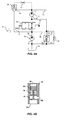
- Figure 1A is a diagrammatic view of a CVT having a hydraulic circuit according to the prior art.
- Figure 1B is a diagrammatic view of the adjustment means according to the prior art.
- Figure 2A is a diagrammatic view of the adjustment means according to the invention.
- Figure 2B is a cross-section of the switch valve of the adjustment means according to the invention.
- FIG. 3 is a further diagrammatic view of the adjustment means according to the invention.
- Figure 4A is a diagrammatic view of a particular development of the adjustment means according to the invention.
- Figure 4B is a diagrammatic view of a non-return valve.
- Figure 1A shows a CVT provided with a primary pulley and a secondary pulley.
- the primary pulley comprises a pulley shaft 1, which can be connected to an input shaft, which is not shown here, of the CVT, a pulley disc 2, which is not displaceable with respect to the pulley shaft 1, or is fixed, and an axially displaceable pulley disc 3.
- the axially displaceable pulley disc 3 of the primary pulley forms a piston/cylinder assembly that has a pressure chamber 4.
- the secondary pulley comprises a pulley shaft 7, which can be connected to an output shaft, which is not shown here, of the CVT, a fixed pulley disc 8 and an axially displaceable pulley disc 9.
- the axially displaceable pulley disc 9 of the secondary pulley forms a piston/cylinder assembly that has a pressure chamber 12.
- a drive belt 14 is fitted between the pulley discs 2 and 3 of the primary pulley and between the pulley discs 8 and 9 of the secondary pulleys to transmit torque between the said pulleys.
- the known CVT further comprises a hydraulic circuit that interacts with a reservoir 16 for hydraulic medium, a filter 19, adjustment means 15, an outflow channel 13, hydraulic channels 6 and 17 and control means 18 for controlling the hydraulic pressure in the pressure chambers 4 and 12.
- the adjustment means 15 are shown in more detail in Figure 1B and interact with two pumps 20 and 21, which are each provided with an inlet opening 24 and 25, respectively, and an outlet opening 26 and 27, respectively.
- the adjustment means 15 comprise a switch valve 28 for switching the pumps 20 and 21 in series or in parallel. In the position of the switch valve 28 shown in Figure 1B the pumps 20 and 21 are switched in series. Via the outflow channel 13, the adjustment means are connected to the other parts of the hydraulic circuit.
- the two pumps 20 and 21 are formed by two pump compartments of one double or multiple vane or roller pump. Via its outlet opening 26, the pump 20 delivers hydraulic medium to the inlet opening 25 of pump 21, which, in turn, delivers hydraulic medium to the outflow channel 13.
- the switch valve 28 By reducing the pressure in the control pressure channel 29 of the switch valve 28 to a sufficient extent, the switch valve 28 switches the pumps 20 and 21, under the influence of a spring 30, into the position in which they are switched in parallel, so that the volume flow delivered jointly by the pumps 20 and 21 is fed to the outflow channel.
- the outlet opening 26 of the first pump 20 and the inlet opening 25 of the second pump 21 are temporarily blocked, as a consequence of which an overpressure and a reduced pressure are built up in the hydraulic system.
- Such pressure fluctuations are undesirable for use in motor vehicles since they produce annoying noise and make control of the CVT more difficult or even disrupt this.
- FIG. 2A shows one development of the adjustment means 15 according to the invention.
- the adjustment means 15 comprise two valves 31 and 33.
- a switch valve 31, that is controllable as a function of the pressure in a control pressure channel 29, is used to make a hydraulic connection between the outlet 26 of the first pump 20 and either the inlet 25 of the second pump 21 or the outflow channel 13.
- the adjustment means further comprise a non-return valve 33 that is used to make and break a hydraulic connection between the inlet 25 of the second pump 21 and the reservoir 16. In the position of the switch valve 31 shown in Figure 2A the non-return valve is opened by the volume flow which is demanded by the second pump 21.
- FIG. 2B shows a cross-section of the switch valve 31.
- the switching element 3 la is at one end subjected to a force originating from a spring 30. At the opposite end, the switching element 3 la is subjected to a force under the influence of hydraulic pressure in a control pressure channel 29.
- the valve 31 can make a hydraulic connection between opening 31d and opening 31c or between opening 31d and opening 31b.
- the opening 31d is hydraulically connected to the other two openings 31b and 31c.
- the adjustment means provide a possibility for setting the switch valve 31 in such a way that a portion of the volume flow delivered by the first pump 20 is fed to the outflow channel 13 and a portion of said volume flow is fed to the inlet 25 of the second pump.
- the volume flow delivered to the outflow channel 13 can be continually adjusted between, on the one hand, the volume flow delivered by the second pump 21 and, on the other hand, the sum of the volume flows delivered by the two pumps 20 and 21.
- Use of the structurally simple switch valve 31 according to Figure 3B has the disadvantage that such a valve 31 is difficult to set, inter alia because the three ports 31b, 31c and 31d are short-circuited during switching.
- the result of the said short-circuiting is that the outlet opening 27 and the inlet opening 25 of the second pump 21 are connected directly to one another, as a consequence of which undesirable pressure variations in the hydraulic circuit can still occur.
- Figure 3 shows a development of the adjustment means 15 according to the invention which largely overcome the disadvantage indicated above.
- the adjustment means 15 comprise three valves 39, 32 and 33.
- a single switch valve 39 that is controllable as a function of the pressure in a control pressure channel 29, is used to make and break a hydraulic connection between the outlet 26 of the first pump 20 and the inlet 25 of the second pump 21. In the position of the switch valve 39 shown in Figure 3, the two pumps 20 and 21 have been switched in series.
- the adjustment means further comprise two non-return valves 32 and 33.
- the first non-return valve 32 is used to make and break a hydraulic connection between the outlet 26 of the first pump 20 and the outflow channel 13.
- the second non-return valve 33 is used to make and break a hydraulic connection between the inlet 25 of the second pump 21 and the reservoir 16.
- Non-return valve 32 is opened by the volume flow that is delivered by pump 20 and non-return valve 33 is opened by the volume flow that is demanded by pump 21.
- the adjustment means 15 have the advantage that switching of the pumps 20 and 21 takes place in a continuous manner, so that neither the said reduced pressure nor the said overpressure is produced. Moreover, the adjustment means provide a possibility for setting the switch valve 39 in such a way that a portion of the volume flow delivered by the first pump 20 is fed to the outflow channel 13 and a portion of said volume flow is fed to the inlet 25 of the second pump. Consequently, the volume flow fed to the outflow channel 13 can be continuously adjusted between, on the one hand, the volume flow delivered by the second pump 21 and, on the other hand, the sum of the volume flows delivered by the two pumps 20 and 21.
- FIG 4A shows a further development of the adjustment means 15 according to the invention.
- the development of the adjustment means 15 shown in Figure 4A is in particular suitable for reliable and smooth switching of two pump compartments 20 and 21 of a multiple roller pump that is able to deliver a large volume flow, it also being possible for the volume flow delivered by the first pump compartment 20 to be greater than the volume flow demanded by the second pump compartment 21.
- the adjustment means 15 are provided with the switch valve 39 that has been described above, a cartridge valve 34 and a non-return valve 35.
- the switch valve is hydraulically damped with the aid of a restriction 41.
- the cartridge valve 34 is pretensioned somewhat by means of a spring 40 and is used to make and break a hydraulic connection between the outlet 26 of the first pump 20 and the outflow channel 13.
- the cartridge valve is provided with hydraulic damping means in the form of a restriction 37.
- the non-return valve 35 is used to make and break a hydraulic connection between the inlet 25 of the second pump 21 and the reservoir 16.
- the non-return valve 35 is pretensioned by means of a spring 36 and is provided with a control pressure channel 38 that is in communication with the outlet 26 of the first pump 20.
- the non-return valve is also provided with a hydraulic restriction 42, switched in parallel.
- the second pump compartment 21 can still be provided with hydraulic medium via restriction 42.
- the switch valve 39 shown in Figure 4A the other two valves 34 and 35 are, in principle, closed and the pumps are switched in series. If the volume flow delivered by the first pump 20 is greater than the volume flow demanded by the second pump 21, the pressure will rise close to the inlet 25 of the second pump 21 until the non-return valve 35 opens and hydraulic medium is discharged to the reservoir 16. The pressure at which the non-return valve 35 opens is dependent on the force exerted by the spring 36.
- the adjustment means 15 function in an optimum manner at a value of the said pressure of between 1 and 3 bar.
- the other two valves 34 and 35 are opened and the pumps 20 and 21 are switched in parallel.
- the pressure drop over the non-return valve 35 is in principle opposed to the direction of passage, said valve 35 is still opened by the presence of a control pressure in the control pressure channel 38.
- Figure 4B is a diagrammatic view of a possible embodiment of the non-return valve 35.
- the switching element 35c makes or breaks a hydraulic connection between a port 35a, which is connected to the reservoir 16, and port 35b, which is connected to the inlet opening 25 of the second pump or the second pump compartment 21. With the aid of control pressure channel 38 the switching element 35c can be opened against the force exerted by the spring 36.
- the said restriction 42 switched in parallel is formed by a bore in the switching element 35c.
Landscapes
- Engineering & Computer Science (AREA)
- General Engineering & Computer Science (AREA)
- Mechanical Engineering (AREA)
- Control Of Transmission Device (AREA)
- Details And Applications Of Rotary Liquid Pumps (AREA)
- Rotary Pumps (AREA)
- Transmissions By Endless Flexible Members (AREA)
Applications Claiming Priority (2)
| Application Number | Priority Date | Filing Date | Title |
|---|---|---|---|
| NL1010144 | 1998-09-21 | ||
| NL1010144A NL1010144C2 (nl) | 1998-09-21 | 1998-09-21 | Continu variabele transmissie. |
Publications (2)
| Publication Number | Publication Date |
|---|---|
| EP0989338A1 true EP0989338A1 (fr) | 2000-03-29 |
| EP0989338B1 EP0989338B1 (fr) | 2002-09-04 |
Family
ID=19767852
Family Applications (1)
| Application Number | Title | Priority Date | Filing Date |
|---|---|---|---|
| EP99203048A Expired - Lifetime EP0989338B1 (fr) | 1998-09-21 | 1999-09-17 | Transmission continue de vitesse |
Country Status (5)
| Country | Link |
|---|---|
| US (1) | US6196806B1 (fr) |
| EP (1) | EP0989338B1 (fr) |
| JP (1) | JP2000266169A (fr) |
| DE (1) | DE69902729T2 (fr) |
| NL (1) | NL1010144C2 (fr) |
Cited By (6)
| Publication number | Priority date | Publication date | Assignee | Title |
|---|---|---|---|---|
| EP1348894A1 (fr) * | 2002-03-29 | 2003-10-01 | Van Doorne's Transmissie B.V. | Transmission à variation continue |
| EP2441985A3 (fr) * | 2010-10-12 | 2012-07-04 | Hyundai Motor Company | Système d'alimentation en huile de transmission automatique |
| CN103370545A (zh) * | 2010-11-08 | 2013-10-23 | 大韩赛斯泰克株式会社 | 恒定流量吐出用增压器 |
| CN104937314A (zh) * | 2013-01-16 | 2015-09-23 | 加特可株式会社 | 变速器的控制装置 |
| CN103671894B (zh) * | 2012-09-03 | 2017-09-05 | 现代自动车株式会社 | 自动变速器的液压供给系统 |
| CN109386607A (zh) * | 2017-08-10 | 2019-02-26 | 本田技研工业株式会社 | 液压控制装置 |
Families Citing this family (28)
| Publication number | Priority date | Publication date | Assignee | Title |
|---|---|---|---|---|
| JP2001304067A (ja) * | 2000-04-20 | 2001-10-31 | Bosch Automotive Systems Corp | 高圧燃料供給ポンプ |
| WO2004046534A1 (fr) * | 2002-11-18 | 2004-06-03 | Breeden Robert H | Systeme de pompe regule par electrovanne |
| US20040179962A1 (en) * | 2003-03-12 | 2004-09-16 | Hopper Mark L. | System and method for regulating pressure in an automatic transmission |
| DE102004002459A1 (de) * | 2004-01-16 | 2005-08-11 | Siemens Ag | Verfahren zur Einstellung der Fördermenge einer aus einem Kraftstofftank Kraftstoff ansaugenden Kraftstoffpumpeneinheit und Kraftstoffpumpeneinheit für das Verfahren |
| JP4513353B2 (ja) * | 2004-02-16 | 2010-07-28 | 株式会社豊田中央研究所 | 変速装置 |
| DE102005028200A1 (de) * | 2005-06-17 | 2006-12-21 | Linde Ag | Kryoverdichter mit Hochdruckphasentrenner |
| WO2008031390A1 (fr) * | 2006-09-14 | 2008-03-20 | Luk Lamellen Und Kupplungsbau Beteiligungs Kg | système hydraulique d'amenée d'un fluide hydraulique à un consommateur |
| US8322252B2 (en) * | 2006-09-29 | 2012-12-04 | Caterpillar Inc. | Step-change transmission having charge and variable displacement pumps |
| US9410544B2 (en) * | 2007-11-01 | 2016-08-09 | Danfoss Power Solutions Aps | Charged hydraulic system |
| JP5012667B2 (ja) * | 2008-05-29 | 2012-08-29 | トヨタ自動車株式会社 | 動力伝達装置 |
| GB2474670B (en) * | 2009-10-22 | 2017-01-04 | Gm Global Tech Operations Llc | Pump arrangement |
| US20120167758A1 (en) * | 2010-11-10 | 2012-07-05 | Marshall Anthony Sapp | Vacuum motor airflow series/parallel switching apparatus |
| KR101339230B1 (ko) | 2011-11-29 | 2013-12-09 | 현대자동차 주식회사 | 자동변속기의 유압제어장치 |
| KR20130060046A (ko) * | 2011-11-29 | 2013-06-07 | 현대자동차주식회사 | 자동변속기의 유압제어장치 |
| WO2013084909A1 (fr) * | 2011-12-09 | 2013-06-13 | 株式会社村田製作所 | Appareil de commande de gaz |
| KR20140032033A (ko) | 2012-09-03 | 2014-03-14 | 현대자동차주식회사 | 차량용 자동변속기의 유압공급시스템 |
| KR101338455B1 (ko) | 2012-09-03 | 2013-12-10 | 현대자동차주식회사 | 차량용 자동변속기의 유압공급시스템 |
| KR101338454B1 (ko) | 2012-09-03 | 2013-12-10 | 현대자동차주식회사 | 차량용 자동변속기의 유압공급시스템 |
| KR101394038B1 (ko) * | 2012-09-03 | 2014-05-12 | 현대자동차 주식회사 | 차량용 자동변속기의 유압공급시스템 |
| KR101405192B1 (ko) | 2012-11-05 | 2014-06-10 | 현대자동차 주식회사 | 차량용 자동변속기의 유압공급시스템 |
| NL1039930C2 (en) * | 2012-12-06 | 2014-06-10 | Bosch Gmbh Robert | Hydraulically actuated continously variable transmission for a vehicular drive line provided with an internal combustion engine. |
| KR101438607B1 (ko) * | 2012-12-12 | 2014-09-05 | 현대자동차 주식회사 | 차량용 자동변속기의 유압공급시스템 |
| KR101484194B1 (ko) * | 2013-04-02 | 2015-01-16 | 현대자동차 주식회사 | 차량용 자동변속기의 유압공급시스템 |
| KR101490915B1 (ko) * | 2013-07-29 | 2015-02-06 | 현대자동차 주식회사 | 차량용 자동변속기의 유압공급시스템 |
| KR101601105B1 (ko) | 2014-07-01 | 2016-03-08 | 현대자동차 주식회사 | 차량용 자동변속기의 유압공급시스템 |
| CA2962461C (fr) | 2014-09-25 | 2022-06-21 | Nuhn Industries Ltd. | Pompe a fluide munie de plusieurs tetes de pompe |
| DE102015223460A1 (de) * | 2015-11-26 | 2017-06-01 | Zf Friedrichshafen Ag | Vorrichtung zur bedarfsorientierten Ölversorgung eines Elementes eines Antriebsstrangs eines Kraftfahrzeugs, insbesondere eines Getriebes oder eines Verbrennungsmotors |
| US9903468B2 (en) * | 2015-12-14 | 2018-02-27 | Hyundai Motor Company | Hydraulic pressure supply system of automatic transmission |
Citations (3)
| Publication number | Priority date | Publication date | Assignee | Title |
|---|---|---|---|---|
| EP0764799A1 (fr) * | 1995-09-25 | 1997-03-26 | Van Doorne's Transmissie B.V. | Transmission à variation continue |
| EP0826910A1 (fr) | 1996-08-26 | 1998-03-04 | Van Doorne's Transmissie B.V. | Variateur continu de vitesse avec au moins deux pompes couplées en série/parallèle |
| DE19653636A1 (de) * | 1996-12-20 | 1998-06-25 | Joachim Friedrich Knauer | Pumpenanordnung mit steuerbarer Betriebsweise |
Family Cites Families (4)
| Publication number | Priority date | Publication date | Assignee | Title |
|---|---|---|---|---|
| US2218565A (en) * | 1937-05-01 | 1940-10-22 | Vickers Inc | Compound positive displacement pump circuit |
| US3838941A (en) * | 1973-05-29 | 1974-10-01 | V Roschupkin | Pumping unit |
| DE3420674C2 (de) * | 1984-06-02 | 1986-10-02 | Danfoss A/S, Nordborg | Druckversorgungseinrichtung für ein Hydrauliksystem |
| US5431545A (en) * | 1993-12-02 | 1995-07-11 | Praxair Technology, Inc. | Pumper system for in-situ pigging applications |
-
1998
- 1998-09-21 NL NL1010144A patent/NL1010144C2/nl not_active IP Right Cessation
-
1999
- 1999-09-17 EP EP99203048A patent/EP0989338B1/fr not_active Expired - Lifetime
- 1999-09-17 DE DE69902729T patent/DE69902729T2/de not_active Expired - Lifetime
- 1999-09-21 JP JP11305901A patent/JP2000266169A/ja active Pending
- 1999-09-21 US US09/400,841 patent/US6196806B1/en not_active Expired - Fee Related
Patent Citations (3)
| Publication number | Priority date | Publication date | Assignee | Title |
|---|---|---|---|---|
| EP0764799A1 (fr) * | 1995-09-25 | 1997-03-26 | Van Doorne's Transmissie B.V. | Transmission à variation continue |
| EP0826910A1 (fr) | 1996-08-26 | 1998-03-04 | Van Doorne's Transmissie B.V. | Variateur continu de vitesse avec au moins deux pompes couplées en série/parallèle |
| DE19653636A1 (de) * | 1996-12-20 | 1998-06-25 | Joachim Friedrich Knauer | Pumpenanordnung mit steuerbarer Betriebsweise |
Cited By (9)
| Publication number | Priority date | Publication date | Assignee | Title |
|---|---|---|---|---|
| EP1348894A1 (fr) * | 2002-03-29 | 2003-10-01 | Van Doorne's Transmissie B.V. | Transmission à variation continue |
| WO2003083329A1 (fr) * | 2002-03-29 | 2003-10-09 | Van Doorne's Transmissie B.V. | Transmission a variation continue |
| EP2441985A3 (fr) * | 2010-10-12 | 2012-07-04 | Hyundai Motor Company | Système d'alimentation en huile de transmission automatique |
| CN103370545A (zh) * | 2010-11-08 | 2013-10-23 | 大韩赛斯泰克株式会社 | 恒定流量吐出用增压器 |
| CN103370545B (zh) * | 2010-11-08 | 2016-04-13 | 大韩赛斯泰克株式会社 | 恒定流量吐出用增压器 |
| CN103671894B (zh) * | 2012-09-03 | 2017-09-05 | 现代自动车株式会社 | 自动变速器的液压供给系统 |
| CN104937314A (zh) * | 2013-01-16 | 2015-09-23 | 加特可株式会社 | 变速器的控制装置 |
| CN109386607A (zh) * | 2017-08-10 | 2019-02-26 | 本田技研工业株式会社 | 液压控制装置 |
| CN109386607B (zh) * | 2017-08-10 | 2019-09-10 | 本田技研工业株式会社 | 液压控制装置 |
Also Published As
| Publication number | Publication date |
|---|---|
| EP0989338B1 (fr) | 2002-09-04 |
| NL1010144C2 (nl) | 2000-03-22 |
| US6196806B1 (en) | 2001-03-06 |
| JP2000266169A (ja) | 2000-09-26 |
| DE69902729D1 (de) | 2002-10-10 |
| DE69902729T2 (de) | 2003-05-15 |
Similar Documents
| Publication | Publication Date | Title |
|---|---|---|
| EP0989338B1 (fr) | Transmission continue de vitesse | |
| JP3989565B2 (ja) | 駆動ユニット | |
| US4798561A (en) | Hydraulic control apparatus for stepless transmission | |
| US4565110A (en) | Hydraulic apparatus for a continuously variable transmission | |
| US8287255B2 (en) | Variable displacement rotary pump | |
| EP2935947B1 (fr) | Transmission variable en continu avec un système de commande hydraulique | |
| US20110118066A1 (en) | Sheave positioning device | |
| KR20150032128A (ko) | 차량용 자동변속기의 유압공급시스템 | |
| US5971876A (en) | Hydraulic emergency control for changing hydraulic oil pressure in the hydraulic conical pulley axial adjustment mechanism of a continuously variable transmission for varying the clamping force ratio | |
| EP0502263B1 (fr) | Transmission continue de vitesse avec une pompe réglable | |
| US4726261A (en) | Transmission shift control valve having fluid pressure distributor valve | |
| JPH11280643A (ja) | 自動変速機用油圧ポンプ装置 | |
| US4609330A (en) | Modular unloading sequencing switching valve assembly for hydraulic system | |
| US20050183571A1 (en) | Flow control apparatus for construction heavy equipment | |
| JP2004360905A (ja) | 車両トランスミッション用油圧装置 | |
| KR100369190B1 (ko) | 무단 변속기용 변속비 제어 시스템 | |
| JPS61105347A (ja) | 無段変速機の油圧制御装置 | |
| JP2830525B2 (ja) | 流体作動系のポンプ容量制御装置 | |
| KR100504419B1 (ko) | 무단변속시에일정한클램핑력비율을조절하는비상유압제어장치 | |
| KR20180085936A (ko) | 가변형 오일 펌프의 유압 제어 장치 | |
| JPS61105352A (ja) | 無段変速機の変速制御装置 | |
| KR20010066660A (ko) | 자동 변속기용 오일펌프 | |
| KR950015025B1 (ko) | 유량제어장치 | |
| KR100836918B1 (ko) | 차량용 무단 변속기의 라인압 제어장치 | |
| KR100211362B1 (ko) | 자동 변속기용 라인압 저하 보상장치 |
Legal Events
| Date | Code | Title | Description |
|---|---|---|---|
| PUAI | Public reference made under article 153(3) epc to a published international application that has entered the european phase |
Free format text: ORIGINAL CODE: 0009012 |
|
| AK | Designated contracting states |
Kind code of ref document: A1 Designated state(s): BE DE FR GB IT NL |
|
| AX | Request for extension of the european patent |
Free format text: AL;LT;LV;MK;RO;SI |
|
| 17P | Request for examination filed |
Effective date: 20000929 |
|
| AKX | Designation fees paid |
Free format text: BE DE FR GB IT NL |
|
| GRAG | Despatch of communication of intention to grant |
Free format text: ORIGINAL CODE: EPIDOS AGRA |
|
| 17Q | First examination report despatched |
Effective date: 20011010 |
|
| GRAG | Despatch of communication of intention to grant |
Free format text: ORIGINAL CODE: EPIDOS AGRA |
|
| GRAH | Despatch of communication of intention to grant a patent |
Free format text: ORIGINAL CODE: EPIDOS IGRA |
|
| GRAH | Despatch of communication of intention to grant a patent |
Free format text: ORIGINAL CODE: EPIDOS IGRA |
|
| GRAA | (expected) grant |
Free format text: ORIGINAL CODE: 0009210 |
|
| AK | Designated contracting states |
Kind code of ref document: B1 Designated state(s): BE DE FR GB IT NL |
|
| PG25 | Lapsed in a contracting state [announced via postgrant information from national office to epo] |
Ref country code: NL Free format text: LAPSE BECAUSE OF FAILURE TO SUBMIT A TRANSLATION OF THE DESCRIPTION OR TO PAY THE FEE WITHIN THE PRESCRIBED TIME-LIMIT Effective date: 20020904 Ref country code: BE Free format text: LAPSE BECAUSE OF FAILURE TO SUBMIT A TRANSLATION OF THE DESCRIPTION OR TO PAY THE FEE WITHIN THE PRESCRIBED TIME-LIMIT Effective date: 20020904 |
|
| REG | Reference to a national code |
Ref country code: GB Ref legal event code: FG4D |
|
| REF | Corresponds to: |
Ref document number: 69902729 Country of ref document: DE Date of ref document: 20021010 |
|
| NLV1 | Nl: lapsed or annulled due to failure to fulfill the requirements of art. 29p and 29m of the patents act | ||
| ET | Fr: translation filed | ||
| PLBE | No opposition filed within time limit |
Free format text: ORIGINAL CODE: 0009261 |
|
| STAA | Information on the status of an ep patent application or granted ep patent |
Free format text: STATUS: NO OPPOSITION FILED WITHIN TIME LIMIT |
|
| 26N | No opposition filed |
Effective date: 20030605 |
|
| PGFP | Annual fee paid to national office [announced via postgrant information from national office to epo] |
Ref country code: GB Payment date: 20090922 Year of fee payment: 11 |
|
| PGFP | Annual fee paid to national office [announced via postgrant information from national office to epo] |
Ref country code: IT Payment date: 20090923 Year of fee payment: 11 |
|
| GBPC | Gb: european patent ceased through non-payment of renewal fee |
Effective date: 20100917 |
|
| PG25 | Lapsed in a contracting state [announced via postgrant information from national office to epo] |
Ref country code: IT Free format text: LAPSE BECAUSE OF NON-PAYMENT OF DUE FEES Effective date: 20100917 |
|
| PG25 | Lapsed in a contracting state [announced via postgrant information from national office to epo] |
Ref country code: GB Free format text: LAPSE BECAUSE OF NON-PAYMENT OF DUE FEES Effective date: 20100917 |
|
| PGFP | Annual fee paid to national office [announced via postgrant information from national office to epo] |
Ref country code: DE Payment date: 20141126 Year of fee payment: 16 Ref country code: FR Payment date: 20140917 Year of fee payment: 16 |
|
| REG | Reference to a national code |
Ref country code: DE Ref legal event code: R119 Ref document number: 69902729 Country of ref document: DE |
|
| REG | Reference to a national code |
Ref country code: FR Ref legal event code: ST Effective date: 20160531 |
|
| PG25 | Lapsed in a contracting state [announced via postgrant information from national office to epo] |
Ref country code: DE Free format text: LAPSE BECAUSE OF NON-PAYMENT OF DUE FEES Effective date: 20160401 |
|
| PG25 | Lapsed in a contracting state [announced via postgrant information from national office to epo] |
Ref country code: FR Free format text: LAPSE BECAUSE OF NON-PAYMENT OF DUE FEES Effective date: 20150930 |