EP0989314B1 - Rollenverbindungsvorrichtung und diese verwendende linearführungseinrichtung - Google Patents
Rollenverbindungsvorrichtung und diese verwendende linearführungseinrichtung Download PDFInfo
- Publication number
- EP0989314B1 EP0989314B1 EP99913583A EP99913583A EP0989314B1 EP 0989314 B1 EP0989314 B1 EP 0989314B1 EP 99913583 A EP99913583 A EP 99913583A EP 99913583 A EP99913583 A EP 99913583A EP 0989314 B1 EP0989314 B1 EP 0989314B1
- Authority
- EP
- European Patent Office
- Prior art keywords
- roller
- rollers
- spacers
- connector
- slider
- Prior art date
- Legal status (The legal status is an assumption and is not a legal conclusion. Google has not performed a legal analysis and makes no representation as to the accuracy of the status listed.)
- Expired - Lifetime
Links
Images


Classifications
-
- F—MECHANICAL ENGINEERING; LIGHTING; HEATING; WEAPONS; BLASTING
- F16—ENGINEERING ELEMENTS AND UNITS; GENERAL MEASURES FOR PRODUCING AND MAINTAINING EFFECTIVE FUNCTIONING OF MACHINES OR INSTALLATIONS; THERMAL INSULATION IN GENERAL
- F16C—SHAFTS; FLEXIBLE SHAFTS; ELEMENTS OR CRANKSHAFT MECHANISMS; ROTARY BODIES OTHER THAN GEARING ELEMENTS; BEARINGS
- F16C29/00—Bearings for parts moving only linearly
- F16C29/04—Ball or roller bearings
- F16C29/06—Ball or roller bearings in which the rolling bodies circulate partly without carrying load
- F16C29/0633—Ball or roller bearings in which the rolling bodies circulate partly without carrying load with a bearing body defining a U-shaped carriage, i.e. surrounding a guide rail or track on three sides
- F16C29/0635—Ball or roller bearings in which the rolling bodies circulate partly without carrying load with a bearing body defining a U-shaped carriage, i.e. surrounding a guide rail or track on three sides whereby the return paths are provided as bores in a main body of the U-shaped carriage, e.g. the main body of the U-shaped carriage is a single part with end caps provided at each end
- F16C29/065—Ball or roller bearings in which the rolling bodies circulate partly without carrying load with a bearing body defining a U-shaped carriage, i.e. surrounding a guide rail or track on three sides whereby the return paths are provided as bores in a main body of the U-shaped carriage, e.g. the main body of the U-shaped carriage is a single part with end caps provided at each end with rollers
-
- F—MECHANICAL ENGINEERING; LIGHTING; HEATING; WEAPONS; BLASTING
- F16—ENGINEERING ELEMENTS AND UNITS; GENERAL MEASURES FOR PRODUCING AND MAINTAINING EFFECTIVE FUNCTIONING OF MACHINES OR INSTALLATIONS; THERMAL INSULATION IN GENERAL
- F16C—SHAFTS; FLEXIBLE SHAFTS; ELEMENTS OR CRANKSHAFT MECHANISMS; ROTARY BODIES OTHER THAN GEARING ELEMENTS; BEARINGS
- F16C33/00—Parts of bearings; Special methods for making bearings or parts thereof
- F16C33/30—Parts of ball or roller bearings
- F16C33/46—Cages for rollers or needles
- F16C33/49—Cages for rollers or needles comb-shaped
-
- F—MECHANICAL ENGINEERING; LIGHTING; HEATING; WEAPONS; BLASTING
- F16—ENGINEERING ELEMENTS AND UNITS; GENERAL MEASURES FOR PRODUCING AND MAINTAINING EFFECTIVE FUNCTIONING OF MACHINES OR INSTALLATIONS; THERMAL INSULATION IN GENERAL
- F16C—SHAFTS; FLEXIBLE SHAFTS; ELEMENTS OR CRANKSHAFT MECHANISMS; ROTARY BODIES OTHER THAN GEARING ELEMENTS; BEARINGS
- F16C33/00—Parts of bearings; Special methods for making bearings or parts thereof
- F16C33/30—Parts of ball or roller bearings
- F16C33/46—Cages for rollers or needles
- F16C33/50—Cages for rollers or needles formed of interconnected members, e.g. chains
- F16C33/506—Cages for rollers or needles formed of interconnected members, e.g. chains formed as a flexible belt
Definitions
- the present invention relates to a roller connector which rotatably retains a plurality of rollers in a line and which is incorporated into an endless roller-circulation path of an endless sliding type linear guide unit and also to an improvement in the linear guide unit of the above-type using such roller connector.
- this linear guide unit in which a slider is movably held in engagement with a track rail through a line of endlessly circulating rollers. More concretely, this linear guide unit comprises a plurality of rollers, a track rail which is arranged on a stationary portion such as a bed and which is provided with roller rolling surfaces and a slider provided with load rolling surfaces on which the rollers roll with respect to the roller rolling surfaces of the track rail while bearing a load thereon and an endless roller-circulation path with the inclusion of the load rolling surfaces whereby the slider having a table or a mechanical apparatus mounted thereon can move freely on the track rail following the endless circulation of the rollers.
- the above-described linear guide unit having the track rail and the slider held in engagement with the track rail through the rollers has the advantage of improving the load bearing capacity of the slider as compared to such type of linear guide unit that makes use of rollers while on the other hand, it has the problem that the so called skewing of the rollers (oscillatory rotation of each roller about its axis) tends to take place. Therefore, it has been an important theme in securing the smooth rotation of the rollers and hence the smooth movement of the slider within the endless roller-circulation path how to prevent the above-described skewing of the rollers.
- roller connector comprising a plurality of rollers connected together in a predetermined posture like a string of beads and a linear guide unit having an endless roller-circulation path of the slider into which the roller connector is incorporated (Japanese Patent Laid-Open No. 52217/1993). As shown in Figs .
- such roller connector comprises a plurality of rollers 100 arranged in a line with the axes of rotation thereof being held parallel to one another, a plurality of spacers 102 interposed among the rollers 100 and provided with concave seats 101 with which the rollers 100 come into sliding contact, respectively, and elongate flexible connecting portions 103 connecting the spacers 102 together and adapted to rotatably retain each of the rollers 100 by causing the spacers to sandwich the roller 100 therebetween from the front and rear sides thereof.
- each of the rollers 100 rolls within the endless roller-circulation path while it is retained in its predetermined posture by means of the spacers 102 from on both front and rear sides so that it is possible to cause the rollers 100 to smoothly circulate through the endless roller-circulation path while preventing the skewing of the rollers 100 and hence it is possible to make smooth the movement of the sliders with respect to the track rail.
- the sectional area of the endless roller-circulation path must be enlarged by a width corresponding to each of the connecting portions connecting the spacers together. Accordingly, if the connecting portions are present on both axial ends of each of the rollers as described above, where, for example, an endless roller-circulation path is formed by opening a roller return path in a slider, the diameter of the roller return path has to be made large so that the rigidity of the slider lowers to that degree which results in hindering the miniaturization of the slider.
- the present invention has been made in view of the above-described problems.
- an object of the invention is to provide a roller connector which can rotatably and stably retain a plurality of rollers in a predetermined posture for a prolonged period of time within an endless roller-circulation path formed in a slider of a linear guide unit.
- Another object of the invention is to provide a roller connector which can improve the rigidity of the slider and contribute to the miniaturization of the slider.
- a further object of the invention is to provide a linear guide unit using such roller connector.
- the roller connector of the present invention comprises a plurality of rollers arranged in a line with the axes of rotation of the rollers being held parallel to one another, a plurality of spacers interposed among the rollers and each provided with a pair of concave seats with which each of the rollers comes into sliding contact and an elongate flexible connecting portion connecting the spacers together, wherein the connecting portion is connected to the spacers at a position at which the connecting portion divides the outer peripheral surface of each of the rollers into two substantially equal parts in the axial direction and that the connecting portion is arranged only on one side of the line of rollers.
- the linear guide unit of the present invention using the above-described roller connector is required to have a structure comprising a number of rollers, a track rail having roller-rolling surfaces and a slider provided with an endless roller-circulation path having load rolling surfaces on which the rollers roll with respect to the roller-rolling surface of the track rail while bearing a load, wherein the above-described roller connector is incorporated into the endless roller-circulation path with the connecting portion of the roller connector lying inside the inner peripheral surface of the endless roller-circulation path of the slider, and wherein the endless roller-circulation path is provided with clearance grooves by which the connecting portion of the roller connector is received and guided.
- each of the rollers is embraced in front and in rear by the adjoining spacers and rolls through the endless roller-circulation path of the slider of the linear guide unit in a state in which it is retained in a predetermined posture by the spacers. Consequently, it becomes possible to effectively prevent each of the rollers from skewing within the endless roller-circulation path.
- the connecting portions connecting the spacers are arranged along both end surfaces of each of the rollers in the axial direction thereof so that the connecting portions tend to become fatigued due to the-application thereon of a force urging the rollers to skew during rolling while, on the contrary, the connecting portion of the roller connector according to the present invention is connected to each of the spacers at a position at which the connecting portion divides the outer peripheral surface of each of the rollers into two substantially equal parts in the axial direction so that the connecting portion does not expand and contract repeatedly due to the above kind of force thereby preventing the breakage of the connecting portion resulting from the fatigue thereof.
- the connecting portion is provided only on one side of the line of rollers, where the roller connector of the present invention is incorporated into the endless roller-circulation path of the slider of the liner guide unit, the sectional area of the endless roller-circulation path can be made smaller than in the case of the conventional roller connector and also where roller return paths are formed in the slider, the lowering of the rigidity of the slider can be avoided and the miniaturization of the slider can be made with ease.
- the spacers be so provided as to prevent the movement of each of the rollers in the axial direction.
- an annular groove may be provided in the central portion of the outer peripheral surface of each of the rollers in the axial direction so that each of the spacers fits in such annular groove so as to come into sliding contact with the roller.
- each of the spacers can be formed from the side opposite to the connecting portion so as to separate the pair of concave seats formed on both sides thereof from the point of view of allowing each of the rollers to keep its suitable posture by the spacers.
- each of the spacers can be kept in sliding contact with the outer peripheral surface of each of the rollers by widening the slit so that the roller can always keep its suitable posture.
- the formation of the slit has the advantage that each of the rollers can be removably mounted between the adjoining spacers with ease.
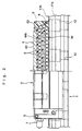
- Figs. 1 and 2 show a linear guide unit using a roller connector according to the present invention.
- reference numeral 1 designates a track rail arranged on a stationary portion such as a bed of a machine tool
- reference numeral 2 designates a slider for guiding a movable body such as a table along the track rail 1
- reference numeral 3 designates rollers capable of rolling between the track rail 1 and the slider 2 while bearing a load and circulating endlessly within the slider 2.
- the track rail 1 is substantially rectangular in shape and is provided with a total of four roller rolling surfaces 11a and 11b extending along the longitudinal direction (vertically in Fig.1) of the slider. These roller rolling surfaces 11a and 11b are formed on both side surfaces and on both edges of the upper surface of the track rail 1, respectively, in such a manner that the roller rolling surfaces 11a on both side surfaces formed inwardly and downwardly at an angle of 30° with respect to the horizontal while the roller rolling surfaces 11b on the upper surface are formed vertically and upwardly.
- the track rail 1 is provided with a plurality of bolt fitting holes 12 arranged in the longitudinal direction of the track rail 1 in spaced-apart relationships with one another and is fixed to the stationary portion by means of fixing bolts (not shown) to be inserted into the bolt fitting holes 12, respectively.
- the slider 2 is formed of a movable block 4 having a fixing surface 41 to which a movable body such as a table is fixed and a plurality of tapped holes 42 into which fixing bolts for the movable body are respectively screw-fitted and a pair of covers 5 to be respectively fixed to the front and rear end surfaces of the movable block 4 whereby an endless roller-circulation path for the rollers 3 is formed within the slider by fixing the covers 5 to the movable block 4. Further, to the covers 5 there are respectively fixed sealing members 6 which come into sliding contact with the track rail 1 whereby the entry of dust adhered to the track rail 1 into the slider 2 due to the movement of the slider 2 is prevented. Note that in the drawings, reference numeral 7 designates a grease nipple for supplying grease into the slider 2.
- the movable block 4 is substantially saddle-shaped in section with the inclusion of a horizontal portion 4a on which the mounting surface 41 is formed and a pair of skirts 4b and 4b extending downward from the horizontal portion 4a. Further, on the lower surface of the horizontal portion 4a and on the inner surface of each of the skirt portions 4b there are formed four load rolling surfaces 43a and 43b in opposite relationships with the roller rolling surfaces 11a and 11b of the track rail 1, respectively. In addition, on the horizontal portions 4a and the skirt portions 4b there are formed roller return ports 44a and 44b so as to correspond to the load rolling surfaces 43a and 43b, respectively.
- This movable block 4 is manufactured by injection-molding a synthetic resin material. That is, it comprises a metallic block 40 and a synthetic resin portion padded to the former by injection-molding and the above-described movable body mounting surface 41 and the load rolling surfaces 43a and 43b of the rollers 3 of which a sufficient mechanical strength is required are formed on the movable block 40 while the roller return ports 44a and 44b of which not so high mechanical strength is required are formed on the synthetic resin portion thereby reducing the weight of the movable block 4 as small as possible.
- the endless circulation path for the rollers becomes complete by fixing the covers 5 to the end surfaces of the movable block 4, respectively. That is, on the inner surface of each of the covers 5 is provided with a U-shaped groove 51 for guiding the rollers 3 which have rolled on the load rolling surfaces 43a and 43b while projecting semicircular roller guide portions 46 are formed on the both end surfaces of the movable block 4 as shown in Fig. 4 so that when the covers 5 are respectively fixed to the end surfaces of the movable block 4, the roller guide portion 46 of the movable block 4 fits in the U-shaped groove 51 of each of the covers 5 to thereby complete a U-shaped change direction path 52 as shown in Fig.2. Thus, by this change direction path 52 the load rolling surfaces 43a and 43b of the movable block 4 and the roller return ports 44a and 44b are connected.
- rollers 3 which are bearing a load between the roller rolling surfaces 11a and 11b of the track rail 1 and the load rolling surfaces 43a and 43b of the movable block 4 have rolled on the load rolling surfaces 43a and 43b with the movement of the slider 2, the rollers 3 are released from the load to enter into the change direction path 52 of one of the covers 5. Then the rollers 3 roll through the roller return ports 44a and 44b of the movable block 4 in a direction reverse to their rolling direction through the load rolling surfaces 43a and 43b in a no-load state. Further, the rollers 3 which have finished rolling through the roller return ports 44a and 44b again enter between the track rail 1 and the movable block 4 through the change direction path 52 of the other cover 5 and roll on the load rolling surfaces 43a and 43b while bearing the load.
- each of the load rolling surfaces 43a and 43b there are formed synthetic resin roller guide portions 45 for guiding both end surfaces of the rollers 3 rolling on the load rolling surfaces 43a and 43b so that the rolling direction of the rollers 3 is regulated by these roller guide portions 45 from on both sides thereof and the skewing of the rollers 3 during their rolling operation is prevented.
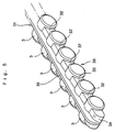
- Figs.5 through 8 show first embodiment of the roller connector of the present invention to be used in the linear guide unit.
- the roller connector 30 comprises a flexible synthetic resin roller connecting member 31 and a plurality of rollers 3 arranged on the roller connecting member 31 in spaced apart relationships with one another with the axes of rotation of the rollers 3 being held parallel to one another.
- the roller connecting member 31 comprises a plurality of spacers 32 interposed among the adjoining rollers 3, respectively, and a band-shaped connecting portion 33 for connecting the spacers 32 and each of the spacers 32 is provided with a pair of concave seats which come into sliding contact with the adjoining rollers 3.
- each of the rollers 3 is held by the spacers 32 from on both front and rear sides of its rolling direction so that the rollers 3 are rotatably retained by the connecting member 31.
- the spacer 32 and the connecting portion 33 at the front or rear end of the roller connector 30 have convex curved guide surfaces 34, respectively, so that the movement of the roller connector 30 at the time of rolling of the rollers 3 is made smooth.
- the connecting portion 33 connecting the spacers 32 is connected to the spacers 32 at a position at which the outer peripheral surface of the roller 3 is divided into substantially two equal parts in the axial direction and the end surfaces of each of the rollers 3 are left open without being covered by the connecting portion 33. Accordingly, the movement of each of the rollers 3 in the axial direction at the time of its rolling is regulated by the above-described roller guide portions 45.
- the connecting portion 33 is provided only on one side of the rollers 3 arranged in a line and with respect to the direction opposite to the other side of the rollers 3, the roller connector 1 is made to bend freely. Consequently, where the roller connector 30 is incorporated into the endless circulation path of the slider 2, the connecting portion 33 is made to lie inside the endless circulation path as shown in Figs.1 and 2.
- roller connector 30 is formed by injection-molding a synthetic resin material in such a manner that the rollers 3 are inserted, as cores, into a mold and by such injection molding, the connecting member 31 comprising each of the spacers 32 and the connecting member 31 which are integral with each other is formed and the roller connector 30 with the rollers 3 arranged along the connecting portion 33 can be taken out of the mold.
- Fig.9 is an enlarged sectional view showing how the rollers 3 roll within the endless roller-circulation path.
- the rollers 3 are incorporated into the endless roller-circulation path of the slider in a state in which they are arranged along the synthetic resin connecting member 31 as described above and the connecting portion 33 of the member 31 which connects the spacers 32 projects outwardly of the outer periphery of each of the rollers 3 so that the load rolling surfaces 43a and 43b of the slider 2 are respectively provided with clearance grooves 47 for receiving the connecting portion 33 while at the same time, similar clearance grooves 48 are respectively formed in the roller return ports 44a and 44b along the longitudinal direction.
- the roller connector 30 circulates through the endless roller circulation path together with the rollers 3 in a state in which the connecting portion 33 of the roller connector 30 is kept received within the clearance grooves 47 and 48.
- the rollers 3 roll between the slider 2 and the track rail 1 and the roller connector 30 circulates through the endless track formed within the slider 2.
- a force urging each of the rolling rollers 3 to skew that is, a force causing the axis of rotation of each of the rollers 3 to oscillate acts on the roller
- the connecting portion 33 of the roller connector 30 of the instant embodiment is connected to the spacers 32 at the position at which the connecting portion 33 connecting the spacers 32 together divides the outer peripheral surface of each of the rollers 3 into two substantially equal parts in the axial direction as shown in Fig.17
- the oscillatory force acts on each of the rollers 3 in the manner shown by the dashed lines about the central portion of the connecting portion 33 so that the connecting portion 33 does not expand and contract due to such oscillatory force.
- the connecting portion for connecting the spacers is provided only on one side of the line of rollers and therefore, when compared to the conventional roller connector having roller connecting portions on both end surfaces of each of the rollers in the axial direction, the size of the roller return port formed in the slider can be reduced and it is possible to improve the mechanical rigidity of the slider to that degree of size-reduction.
- the roller connector 70 comprises a connecting member 71 made of a flexible synthetic resin material and a plurality of rollers 8 arranged along the connecting member 71 in spaced apart relationships with one another with the axes of rotation of the rollers 8 being held parallel to one another.
- the connecting member 71 comprises a plurality of spacers 72 interposed among the adjoining rollers 8 and a band-shaped connecting portion 73 for connecting the spacers 72 together wherein each of the spacers 72 is provided with a pair of concave seats 74 which come into sliding contact with the adjoining roller 8.
- each of the rollers 8 is provided on the peripheral surface thereof with an annular groove 81 so as to bisect the peripheral surface of the roller in the axial direction so that each of the spacers 72 fits in this annular groove 81 and the pair of concave seats 74 are in sliding contact with the roller 8 within the annular groove 81. Accordingly, each of the rollers 8 is embraced by the spacers 72 on both front and rear sides in the rolling direction thereof and is rotatably retained by the connecting member 71 while the movement of the roller 8 in the axial direction is held stopped by the spacers 72 fitted into the annular groove 81.
- each of the spacers 72 is provided with a slit 75 which is so formed as to separate the pair of concave seats 74 formed on both sides thereof, respectively, as shown in Figs.13 and 14. More concretely, this slit 75 is formed in each of the spacers 72 from on the side opposite to the connecting portion 73.
- each of the slits 75 opens wide when the roller connector 70 bends in the shape of the letter-U within the change direction path 52 as shown in Fig. 15 so that the spacer 72 bisected by the slit 75 can maintain a state in which the concave seats 74 are in sliding contact with each of the rollers 8. Consequently, the spacers 72 lying on both sides of each of the rollers 8 within the change direction path 52 securely retain the roller 8 thereby constantly stabilizing the posture of each of the rollers 8 rolling within the endless roller-circulation path of the slider.
- the connecting member 71 provided with the spacers 72 and the connecting portion 73 is formed by injection-molding of a synthetic resin material but unlike the roller connector 30 of the first embodiment, each of the rollers 8 is mounted on the connecting member 71 after the connecting member 71 has been formed by molding.
- the slit 75 is formed in each of the spacers 72, so that in contrast to the connecting member of the first embodiment which is not provided with slits, the space between the pair of concave seats 74 retaining the rollers 8 can be opened wide with ease whereby each of the rollers 8 can be mounted between the spacers 72 with ease.
- the replacement of the rollers 8 mounted on the connecting member 71 can be performed with ease so that the amount of pre-load on the linear guide unit can be adjusted with ease.
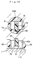
- Fig.16 is an enlarged sectional view showing a state in which the roller connector 70 of the second embodiment of the present invention is incorporated into the endless circulation path of the linear guide unit shown in Figs.1 and 2.
- the connecting portion 73 which connects the spacers 72 together projects outwardly of the outer peripheral surfaces of the rollers 8 so that it is received within the clearance grooves 47 formed in the load rolling surfaces 43a and 43b of the slider 2 and also in the clearance grooves 48 formed in the roller return ports 44a and 44b. Consequently, where the roller connector 70 circulates through the endless roller-circulation path of the slider 2, the connecting portion 73 of the roller connector 70 of the second embodiment can be always guided by the clearance grooves 47 and 48 on the side of the slider 2.
- the roller connector 70 of this second embodiment is constructed such that the connecting portion 33 which connects the spacers 32 together is connected to each of the spacers 32 at a position at which the connecting portion 33 divides the outer peripheral surface of each of the rollers 3 into two substantially equal parts in the axial direction and further, it is provided only on one side of the line of rollers so that the second embodiment of the invention produces the same operation and effect as in the case of the first embodiment.
- the spacers 72 formed integral with the connecting portion 73 stop the axial movement of each of the rollers 8, when the connecting portion 73 is guided by the clearance grooves 47 and 48, the rollers 8 are also guided by these clearance grooves 47 and 48 whereby the axial movement of each of the rollers through the endless roller-circulation path can be prevented by the clearance grooves 47 and 48. Therefore, where the roller connector 70 of the second embodiment is incorporated into the endless roller-circulation path of the linear guide unit for use, the endless circulation of the rollers can be guided smoothly without the necessity of providing roller guides 45 on both sides of the load rolling surfaces 43a and 43b so as to guide both end surfaces of each of the rollers 8 thereby simplifying the structure of the linear guide unit.
- roller connector 70 of the second embodiment can be bent smoothly within the change direction path 52 of the slider due to the provision of the slit 75 in each of the spacers 72 but the roller connector 30 of the first embodiment will be able to be done so if the same slit is formed in each of the spacers 32 of the roller connector 30.
- the connecting member 31 of the first embodiment and the connecting member 71 of the second embodiment are made of a synthetic resin material but the spacers 32 and the connecting portion 33 forming the connecting member 31 or the spacers 72 and the connecting portion 73 forming the connecting member 71 may be formed integral with each other by using the same material or by using different materials.
- the material for forming the connecting portion 33 (73) have an anti-abrasion property higher than that for the spacer 32(72).
- the connecting portion which connects the spacers interposed among the adjoining rollers is connected to each of the spacers at a position at which it divides the outer peripheral surface of each of the rollers into two substantially equal parts in the axial direction so that the connecting portion does not get fatigued at the early stage of operation due to a force urging the rolling rollers to skew with the advantages that there is no fear of breakage of the roller connector within the endless roller-circulation path of the linear guide unit and it is possible to secure the smooth movement of the slider with respect to the track rail for a prolonged period of time.
- roller connector of the present invention is incorporated into the endless roller-circulation path of the slider of the liner guide unit, it is possible to make the sectional area of the endless roller-circulation path for the passage of the rollers therethrough smaller than that of the conventional roller connector. Consequently, it becomes possible to prevent the lowering of the rigidity of the slider thereby improving the moving accuracy and the load bearing capacity of the slider and also to make the slider compact with ease.
Landscapes
- Engineering & Computer Science (AREA)
- General Engineering & Computer Science (AREA)
- Mechanical Engineering (AREA)
- Bearings For Parts Moving Linearly (AREA)
Claims (4)
- Rollenverbinder (30;70), umfassend eine Mehrzahl von Rollen (3;8), welche in einer Linie angeordnet sind, während die Drehachsen davon parallel zueinander gehalten sind, eine Mehrzahl von Abstandshaltern (32;72), welche zwischen den Rollen (3;8) angeordnet und mit konkaven Sitzen, mit welchen die Rollen (3;8) in Gleitkontakt kommen, versehen sind, und einen länglichen flexiblen Verbindungsabschnitt (33;73), welcher geeignet ist, die Abstandshalter (32;72) miteinander zu verbinden, wobei der Verbindungsabschnitt (33;73) mit den Abstandshaltern (32;72) an einer Stelle, an welcher die äußere Umfangsfläche jeder Rolle (3;8) in der axialen Richtung in zwei im Wesentlichen gleiche Teile geteilt ist, verbunden ist und nur an einer Seite der Linie von Rollen (3;8) angeordnet ist.
- Rollenverbinder nach Anspruch 1, wobei eine ringförmige Nut auf der äußeren Umfangsfläche jeder Rolle (8) an einer Stelle, entlang welcher die äußere Umfangsfläche in der axialen Richtung halbiert ist, ausgebildet ist und jeder Abstandshalter (72) in die ringförmige Nut (81) passt, um mit jeder Rolle (8) in Gleitkontakt zu kommen.
- Rollenverbinder nach Anspruch 1, wobei jeder Abstandshalter (72) mit einem Paar von konkaven Sitzen (74) jeweils auf beiden Seiten davon und einem Schlitz (75) versehen ist, welcher auf der Seite gegenüber dem Verbindungsabschnitt (73) ausgebildet ist, um das Paar von konkaven Sitzen (74) zu trennen.
- Lineare Führungseinheit, umfassend einen Rollenverbinder, welcher eine Mehrzahl von Rollen (3;8) hält, einen Schienenstrang (1) mit Rolloberflächen (11a, b) für die Rollen (3;8); und einen Schieber (2) mit einer kontinuierlichen Rollenumlaufbahn, welche Lastrolloberflächen (43) umfasst, entlang welcher die Rollen (3;8) in Bezug auf die Rolloberflächen (11) des Schienenstrangs (1) rollen, während sie eine Last darauf tragen, wobei der Rollenverbinder, welcher in Anspruch 1 bis 3 beansprucht wird, auf eine derartige Weise in die kontinuierliche Rollenumlaufbahn des Schiebers (2) eingebunden ist, dass der Verbindungsabschnitt (33;73) des Rollenverbinders (30;70) auf dem inneren Umfangsflächenabschnitt der kontinuierlichen Rollenumlaufbahn zu liegen kommt, und die kontinuierliche Rollenumlaufbahn mit Gleitraumnuten (47;48) versehen ist, durch welche der Verbindungsabschnitt (33;73) des Rollenverbinders (30;70) aufgenommen und geführt wird.
Applications Claiming Priority (3)
| Application Number | Priority Date | Filing Date | Title |
|---|---|---|---|
| JP9781698 | 1998-04-09 | ||
| JP9781698 | 1998-04-09 | ||
| PCT/JP1999/001867 WO1999053208A1 (fr) | 1998-04-09 | 1999-04-08 | Corps relie par des galets et dispositif de guidage lineaire |
Publications (3)
| Publication Number | Publication Date |
|---|---|
| EP0989314A1 EP0989314A1 (de) | 2000-03-29 |
| EP0989314A4 EP0989314A4 (de) | 2003-03-05 |
| EP0989314B1 true EP0989314B1 (de) | 2003-12-03 |
Family
ID=14202278
Family Applications (1)
| Application Number | Title | Priority Date | Filing Date |
|---|---|---|---|
| EP99913583A Expired - Lifetime EP0989314B1 (de) | 1998-04-09 | 1999-04-08 | Rollenverbindungsvorrichtung und diese verwendende linearführungseinrichtung |
Country Status (6)
| Country | Link |
|---|---|
| US (1) | US6390678B1 (de) |
| EP (1) | EP0989314B1 (de) |
| KR (1) | KR100465383B1 (de) |
| DE (1) | DE69913280T2 (de) |
| TW (1) | TW399127B (de) |
| WO (1) | WO1999053208A1 (de) |
Families Citing this family (12)
| Publication number | Priority date | Publication date | Assignee | Title |
|---|---|---|---|---|
| JP4515589B2 (ja) * | 2000-03-21 | 2010-08-04 | Thk株式会社 | ローラ用リテーナ及びこれを用いた直動案内装置並びにローラねじ |
| US7121724B2 (en) * | 2003-01-29 | 2006-10-17 | Mao Tu Lee | Linear motion guide device |
| US20050249628A1 (en) * | 2004-05-07 | 2005-11-10 | Slady Hsu | Method for making slider of linear bearing |
| US20060034553A1 (en) * | 2004-07-14 | 2006-02-16 | Nsk Ltd. | Linear guide bearing apparatus |
| US7896549B2 (en) * | 2005-10-07 | 2011-03-01 | Hiwin Technologies Corp. | Parallel spacer for a linear guideway |
| TWI273185B (en) * | 2005-11-11 | 2007-02-11 | Chieftech Prec Co Ltd | Ball chain |
| US7377694B2 (en) * | 2006-02-26 | 2008-05-27 | Hiwin Technologies Corp. | Roller connecting and retaining device |
| DE102006012623A1 (de) * | 2006-03-20 | 2007-09-27 | Schaeffler Kg | Wälzkörperkette |
| DE102006015728B4 (de) * | 2006-04-04 | 2010-11-11 | Hiwin Technologies Corp. | Vorrichtung zum Verbinden sowie Halten von Rollen |
| US20070242907A1 (en) * | 2006-04-13 | 2007-10-18 | Hiwin Technologies Corp. | Roller holder for motion guide device |
| US20080019622A1 (en) * | 2006-07-19 | 2008-01-24 | Hiwin Technologies Corp. | Roller holder for motion guide device |
| TWM434859U (en) * | 2011-11-25 | 2012-08-01 | Kuo-Le Tsao | Linear slider structure improvement |
Family Cites Families (9)
| Publication number | Priority date | Publication date | Assignee | Title |
|---|---|---|---|---|
| DE2416198A1 (de) * | 1974-04-03 | 1975-10-16 | Schaeffler Ohg Industriewerk | Waelzlager zur laengsbeweglichen lagerung eines teiles mit ebener laufflaeche |
| US4561703A (en) * | 1982-07-29 | 1985-12-31 | Gustav Dabringhaus Revocable Trust | Linear recirculating roller bearing assembly |
| JPH0466421U (de) * | 1990-10-19 | 1992-06-11 | ||
| JP2607993B2 (ja) * | 1991-08-22 | 1997-05-07 | テイエチケー 株式会社 | ボールチェイン及び直線運動案内装置 |
| JPH0672610B2 (ja) * | 1991-11-05 | 1994-09-14 | テイエチケー株式会社 | 複列ボ−ルチェイン |
| JPH0672612B2 (ja) * | 1992-01-17 | 1994-09-14 | テイエチケー株式会社 | ボ−ルチェイン |
| JPH0640451U (ja) * | 1992-10-28 | 1994-05-31 | 株式会社エノモト | クロスローラーベアリング及びクロスローラーベアリング用ローラー |
| JP3533031B2 (ja) * | 1996-02-23 | 2004-05-31 | Thk株式会社 | ボールスプラインユニットおよびボールスプラインユニットの外筒成形方法 |
| JP3299450B2 (ja) * | 1996-09-13 | 2002-07-08 | テイエチケー株式会社 | 直線運動案内装置およびその転動体チェインの組み込み方法 |
-
1999
- 1999-04-08 EP EP99913583A patent/EP0989314B1/de not_active Expired - Lifetime
- 1999-04-08 WO PCT/JP1999/001867 patent/WO1999053208A1/ja active IP Right Grant
- 1999-04-08 US US09/424,831 patent/US6390678B1/en not_active Expired - Lifetime
- 1999-04-08 DE DE69913280T patent/DE69913280T2/de not_active Expired - Lifetime
- 1999-04-08 KR KR10-1999-7011573A patent/KR100465383B1/ko not_active IP Right Cessation
- 1999-04-09 TW TW088105691A patent/TW399127B/zh not_active IP Right Cessation
Also Published As
| Publication number | Publication date |
|---|---|
| KR20010013566A (ko) | 2001-02-26 |
| DE69913280D1 (de) | 2004-01-15 |
| EP0989314A1 (de) | 2000-03-29 |
| US6390678B1 (en) | 2002-05-21 |
| KR100465383B1 (ko) | 2005-01-13 |
| WO1999053208A1 (fr) | 1999-10-21 |
| TW399127B (en) | 2000-07-21 |
| EP0989314A4 (de) | 2003-03-05 |
| DE69913280T2 (de) | 2004-05-27 |
Similar Documents
| Publication | Publication Date | Title |
|---|---|---|
| US6116783A (en) | Ball chain | |
| EP0989314B1 (de) | Rollenverbindungsvorrichtung und diese verwendende linearführungseinrichtung | |
| US5951168A (en) | Rolling guide apparatus | |
| US20070147714A1 (en) | Accommodation belt for rolling element, and linear guide apparatus | |
| US5277498A (en) | Linear guide device | |
| JPH1122727A (ja) | 転動体連結体及びこれを用いた直線案内装置並びに転動体ねじ装置 | |
| JP6185752B2 (ja) | 運動案内装置 | |
| JPH112241A (ja) | 転動体付ベルト | |
| JP3343195B2 (ja) | ローラチェイン | |
| EP1403541B1 (de) | Linearwälzlager mit in einem flexibelen Käfig festgehaltenen Rollen | |
| JPH0672612B2 (ja) | ボ−ルチェイン | |
| JP4513994B2 (ja) | ローラ連結体及びこれを用いた直線案内装置 | |
| JP3231532B2 (ja) | 直線案内装置 | |
| JPH0672611B2 (ja) | ボ−ルチェイン | |
| JP3256363B2 (ja) | 直線案内装置 | |
| JP4008066B2 (ja) | 転動体連結体 | |
| JPH09303390A (ja) | 直線ローラ案内装置 | |
| US7309162B2 (en) | Linear guide | |
| JP4556830B2 (ja) | 直動案内装置用転動体収容ベルトおよび直動案内装置 | |
| JP3646248B2 (ja) | ローラ連結体及びローラ案内装置 | |
| JP2008249043A (ja) | 転動体収容ベルトおよび直動案内装置 | |
| JP3670826B2 (ja) | 転動体連結体 | |
| JP2002013531A (ja) | 直線案内装置 | |
| JP4257448B2 (ja) | ローラ案内装置 | |
| TW202346730A (zh) | 運動導引裝置 |
Legal Events
| Date | Code | Title | Description |
|---|---|---|---|
| PUAI | Public reference made under article 153(3) epc to a published international application that has entered the european phase |
Free format text: ORIGINAL CODE: 0009012 |
|
| 17P | Request for examination filed |
Effective date: 19991227 |
|
| AK | Designated contracting states |
Kind code of ref document: A1 Designated state(s): DE GB IT |
|
| A4 | Supplementary search report drawn up and despatched |
Effective date: 20030120 |
|
| RIC1 | Information provided on ipc code assigned before grant |
Ipc: 7F 16C 33/50 B Ipc: 7F 16C 29/06 A |
|
| GRAH | Despatch of communication of intention to grant a patent |
Free format text: ORIGINAL CODE: EPIDOS IGRA |
|
| RTI1 | Title (correction) |
Free format text: ROLLER CONNECTOR AND LINEAR GUIDE UNIT USING THE SAME |
|
| GRAS | Grant fee paid |
Free format text: ORIGINAL CODE: EPIDOSNIGR3 |
|
| GRAA | (expected) grant |
Free format text: ORIGINAL CODE: 0009210 |
|
| AK | Designated contracting states |
Kind code of ref document: B1 Designated state(s): DE GB IT |
|
| REG | Reference to a national code |
Ref country code: GB Ref legal event code: FG4D |
|
| REF | Corresponds to: |
Ref document number: 69913280 Country of ref document: DE Date of ref document: 20040115 Kind code of ref document: P |
|
| PLBE | No opposition filed within time limit |
Free format text: ORIGINAL CODE: 0009261 |
|
| STAA | Information on the status of an ep patent application or granted ep patent |
Free format text: STATUS: NO OPPOSITION FILED WITHIN TIME LIMIT |
|
| 26N | No opposition filed |
Effective date: 20040906 |
|
| PGFP | Annual fee paid to national office [announced via postgrant information from national office to epo] |
Ref country code: GB Payment date: 20150408 Year of fee payment: 17 Ref country code: DE Payment date: 20150331 Year of fee payment: 17 |
|
| PGFP | Annual fee paid to national office [announced via postgrant information from national office to epo] |
Ref country code: IT Payment date: 20150410 Year of fee payment: 17 |
|
| REG | Reference to a national code |
Ref country code: DE Ref legal event code: R119 Ref document number: 69913280 Country of ref document: DE |
|
| GBPC | Gb: european patent ceased through non-payment of renewal fee |
Effective date: 20160408 |
|
| PG25 | Lapsed in a contracting state [announced via postgrant information from national office to epo] |
Ref country code: DE Free format text: LAPSE BECAUSE OF NON-PAYMENT OF DUE FEES Effective date: 20161101 Ref country code: GB Free format text: LAPSE BECAUSE OF NON-PAYMENT OF DUE FEES Effective date: 20160408 |
|
| PG25 | Lapsed in a contracting state [announced via postgrant information from national office to epo] |
Ref country code: IT Free format text: LAPSE BECAUSE OF NON-PAYMENT OF DUE FEES Effective date: 20160408 |