EP0988477B1 - Verfahren und einrichtung zur lastschaltbaren umschaltung eines hydrostatischen fahrantriebes einer mobilen baumaschine - Google Patents
Verfahren und einrichtung zur lastschaltbaren umschaltung eines hydrostatischen fahrantriebes einer mobilen baumaschine Download PDFInfo
- Publication number
- EP0988477B1 EP0988477B1 EP99908862A EP99908862A EP0988477B1 EP 0988477 B1 EP0988477 B1 EP 0988477B1 EP 99908862 A EP99908862 A EP 99908862A EP 99908862 A EP99908862 A EP 99908862A EP 0988477 B1 EP0988477 B1 EP 0988477B1
- Authority
- EP
- European Patent Office
- Prior art keywords
- switch
- pressure
- frequency
- changeover
- power
- Prior art date
- Legal status (The legal status is an assumption and is not a legal conclusion. Google has not performed a legal analysis and makes no representation as to the accuracy of the status listed.)
- Expired - Lifetime
Links
- 238000010276 construction Methods 0.000 title claims abstract description 26
- 230000002706 hydrostatic effect Effects 0.000 title claims abstract description 19
- 238000000034 method Methods 0.000 title claims abstract description 19
- 230000001419 dependent effect Effects 0.000 claims abstract description 40
- 230000005540 biological transmission Effects 0.000 claims abstract description 32
- 230000000694 effects Effects 0.000 claims description 5
- 230000001105 regulatory effect Effects 0.000 claims description 3
- 238000012544 monitoring process Methods 0.000 claims 2
- 230000009747 swallowing Effects 0.000 description 5
- 239000003999 initiator Substances 0.000 description 2
- 238000010521 absorption reaction Methods 0.000 description 1
- 230000007423 decrease Effects 0.000 description 1
- 238000010586 diagram Methods 0.000 description 1
- 238000011156 evaluation Methods 0.000 description 1
Images

Classifications
-
- F—MECHANICAL ENGINEERING; LIGHTING; HEATING; WEAPONS; BLASTING
- F16—ENGINEERING ELEMENTS AND UNITS; GENERAL MEASURES FOR PRODUCING AND MAINTAINING EFFECTIVE FUNCTIONING OF MACHINES OR INSTALLATIONS; THERMAL INSULATION IN GENERAL
- F16H—GEARING
- F16H61/00—Control functions within control units of change-speed- or reversing-gearings for conveying rotary motion ; Control of exclusively fluid gearing, friction gearing, gearings with endless flexible members or other particular types of gearing
- F16H61/38—Control of exclusively fluid gearing
- F16H61/40—Control of exclusively fluid gearing hydrostatic
- F16H61/42—Control of exclusively fluid gearing hydrostatic involving adjustment of a pump or motor with adjustable output or capacity
- F16H61/423—Motor capacity control by fluid pressure control means
-
- E—FIXED CONSTRUCTIONS
- E02—HYDRAULIC ENGINEERING; FOUNDATIONS; SOIL SHIFTING
- E02F—DREDGING; SOIL-SHIFTING
- E02F9/00—Component parts of dredgers or soil-shifting machines, not restricted to one of the kinds covered by groups E02F3/00 - E02F7/00
- E02F9/20—Drives; Control devices
- E02F9/22—Hydraulic or pneumatic drives
- E02F9/2278—Hydraulic circuits
- E02F9/2296—Systems with a variable displacement pump
-
- F—MECHANICAL ENGINEERING; LIGHTING; HEATING; WEAPONS; BLASTING
- F16—ENGINEERING ELEMENTS AND UNITS; GENERAL MEASURES FOR PRODUCING AND MAINTAINING EFFECTIVE FUNCTIONING OF MACHINES OR INSTALLATIONS; THERMAL INSULATION IN GENERAL
- F16H—GEARING
- F16H47/00—Combinations of mechanical gearing with fluid clutches or fluid gearing
- F16H47/02—Combinations of mechanical gearing with fluid clutches or fluid gearing the fluid gearing being of the volumetric type
-
- F—MECHANICAL ENGINEERING; LIGHTING; HEATING; WEAPONS; BLASTING
- F16—ENGINEERING ELEMENTS AND UNITS; GENERAL MEASURES FOR PRODUCING AND MAINTAINING EFFECTIVE FUNCTIONING OF MACHINES OR INSTALLATIONS; THERMAL INSULATION IN GENERAL
- F16H—GEARING
- F16H59/00—Control inputs to control units of change-speed- or reversing-gearings for conveying rotary motion
- F16H59/68—Inputs being a function of gearing status
- F16H2059/6838—Sensing gearing status of hydrostatic transmissions
- F16H2059/6861—Sensing gearing status of hydrostatic transmissions the pressures, e.g. high, low or differential pressures
-
- F—MECHANICAL ENGINEERING; LIGHTING; HEATING; WEAPONS; BLASTING
- F16—ENGINEERING ELEMENTS AND UNITS; GENERAL MEASURES FOR PRODUCING AND MAINTAINING EFFECTIVE FUNCTIONING OF MACHINES OR INSTALLATIONS; THERMAL INSULATION IN GENERAL
- F16H—GEARING
- F16H59/00—Control inputs to control units of change-speed- or reversing-gearings for conveying rotary motion
- F16H59/14—Inputs being a function of torque or torque demand
- F16H59/26—Inputs being a function of torque or torque demand dependent on pressure
-
- F—MECHANICAL ENGINEERING; LIGHTING; HEATING; WEAPONS; BLASTING
- F16—ENGINEERING ELEMENTS AND UNITS; GENERAL MEASURES FOR PRODUCING AND MAINTAINING EFFECTIVE FUNCTIONING OF MACHINES OR INSTALLATIONS; THERMAL INSULATION IN GENERAL
- F16H—GEARING
- F16H59/00—Control inputs to control units of change-speed- or reversing-gearings for conveying rotary motion
- F16H59/36—Inputs being a function of speed
- F16H59/38—Inputs being a function of speed of gearing elements
- F16H59/40—Output shaft speed
-
- F—MECHANICAL ENGINEERING; LIGHTING; HEATING; WEAPONS; BLASTING
- F16—ENGINEERING ELEMENTS AND UNITS; GENERAL MEASURES FOR PRODUCING AND MAINTAINING EFFECTIVE FUNCTIONING OF MACHINES OR INSTALLATIONS; THERMAL INSULATION IN GENERAL
- F16H—GEARING
- F16H61/00—Control functions within control units of change-speed- or reversing-gearings for conveying rotary motion ; Control of exclusively fluid gearing, friction gearing, gearings with endless flexible members or other particular types of gearing
- F16H61/02—Control functions within control units of change-speed- or reversing-gearings for conveying rotary motion ; Control of exclusively fluid gearing, friction gearing, gearings with endless flexible members or other particular types of gearing characterised by the signals used
- F16H61/0202—Control functions within control units of change-speed- or reversing-gearings for conveying rotary motion ; Control of exclusively fluid gearing, friction gearing, gearings with endless flexible members or other particular types of gearing characterised by the signals used the signals being electric
- F16H61/0204—Control functions within control units of change-speed- or reversing-gearings for conveying rotary motion ; Control of exclusively fluid gearing, friction gearing, gearings with endless flexible members or other particular types of gearing characterised by the signals used the signals being electric for gearshift control, e.g. control functions for performing shifting or generation of shift signal
- F16H61/0213—Control functions within control units of change-speed- or reversing-gearings for conveying rotary motion ; Control of exclusively fluid gearing, friction gearing, gearings with endless flexible members or other particular types of gearing characterised by the signals used the signals being electric for gearshift control, e.g. control functions for performing shifting or generation of shift signal characterised by the method for generating shift signals
-
- F—MECHANICAL ENGINEERING; LIGHTING; HEATING; WEAPONS; BLASTING
- F16—ENGINEERING ELEMENTS AND UNITS; GENERAL MEASURES FOR PRODUCING AND MAINTAINING EFFECTIVE FUNCTIONING OF MACHINES OR INSTALLATIONS; THERMAL INSULATION IN GENERAL
- F16H—GEARING
- F16H61/00—Control functions within control units of change-speed- or reversing-gearings for conveying rotary motion ; Control of exclusively fluid gearing, friction gearing, gearings with endless flexible members or other particular types of gearing
- F16H61/16—Inhibiting or initiating shift during unfavourable conditions , e.g. preventing forward-reverse shift at high vehicle speed, preventing engine overspeed
Definitions
- the invention relates to a method and a device with the features according to the preamble of claim 1 or 9.
- DE 195 20 454 C1 from the applicant is a method and a device for load-dependent automatic switching at least one two-stage hydraulic Drive motor of a mobile construction machine known in which by operating a switch at least two with at least a switching element in operative connection Pressure switches with different hydraulic response pressures can be activated one after the other, using depending on one or the other pressure switch specified load conditions in the hydraulic Drive circuit operated changeover valve on the changeover of the traction motor from its maximum swallowing volume lowest swallowing volume and vice versa effecting valve is controlled electrically.
- This known method therefore concerns an automatic switchover of a two-stage hydraulic driving motor, however not a generic method in which a powershift transmission to be switched.
- the object of the invention is a generic method and to further develop a generic device in such a way that depending on the load between the switching stages of the Powershift transmission automatically switched over in a reliable manner can be so that the entire driving range from minimal up to maximum speed at different Drive through driving resistances without manual switching can be.
- driving safety should increase and a danger to the construction machine components during the switching process be safely avoided.
- An automatic switchover is thus according to the invention provided by the driver by actuation a switch can be activated.
- a switch can be activated.
- a relay switching element or equivalent devices creates a switching window, which, on the one hand, automatically switches to both Directions (level 1 after level 2 and level 2 after level 1) enables and on the other hand unnecessarily frequent switching prevented. Switching is dependent hydrostatic pressure in the driving circuit (maximum or Minimum value).
- the construction machine is monitored and exceeded a predetermined speed value Downshifting the powershift transmission is prevented.
- a vehicle speed proportional Frequency signal from a Evaluation unit evaluated and via a frequency-dependent Switch enables or prevents switching becomes.
- the frequency-dependent switch on the changeover valve acts.
- the frequency-dependent switch acts on an additional valve, which is arranged parallel to the changeover valve and is hydraulically linked to it.
- the driving speed the construction machine is monitored and at a standstill the construction machine automatically switches back the lowest gear of the powershift transmission takes place.
- This can also expediently be via the frequency-dependent Switches are made via which are determined whether the vehicle is stationary or not. This can an additional frequency-dependent switch is also provided become.
- that the lower response pressure of the pressure switch is set is that he has a pressure of the control pump in the area corresponds to their maximum output.
- the upper response pressure the pressure switch is set so that it is in the range of the maximum system pressure.
- the invention proposes to achieve the object stated at the outset also a device with the features of claim 9 before.
- the switch is usually located in the cab the construction machine and makes the choice between manual and automatic switching.
- the one with the pressure switches connected switching element can preferably be used as a relay be trained.
- the frequency-dependent switch is advantageous in operative connection with the changeover valve.
- you can but it should also be provided that the frequency-dependent Switch with an additional valve in operative connection is arranged in parallel to the switching valve and with this is hydraulically linked.
- the frequency-dependent Switch has a first output that a relay with the changeover valve in operative connection stands.
- this relay it is possible to control the frequency and thus speed-dependent switching only when reducing the speed, i.e. when downshifting of the powershift transmission to take effect to avoid a load-independent upshift. This ensures that the upshift only depends on the load he follows.
- the frequency-dependent Switch has a second output that over another relay with the changeover valve in operative connection stands, with the further relay between the switching element and the switch and the relay arranged is.
- the frequency-dependent switch can in the above Way have two outputs, alternatively can be provided that the frequency-dependent switch of two separate switches, each with an output is.
- the pressure switch, the switching element, the frequency-dependent switch and the relays as common electronic, hydraulic or pneumatic Switching logic are formed.
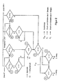
- An exemplary hydrostatic drive a mobile construction machine generally has one 2, 10 designated driving circuit and a connected to it Powershift transmission 1, which is shown in the Embodiment is two-stage, that is, a first and has a second gear.
- the powershift transmission 1 has two output axes that drive the Steering axis and as a drive for the rigid axis of the construction machine serve.
- the driving circuit 2, 10 has the usual elements that not explained in detail at this point.
- a hydrostatic control pump is not shown, which is only indicated by an arrow 10.
- in the Drive circuit 2, 10 is a hydraulic shuttle valve 11 arranged.
- This hydraulic shuttle valve 11 About this hydraulic shuttle valve 11 are to the Driving circuit two parallel pressure switches 3 and 4 connected, which serve as switching elements and different have hydraulic response pressures. Both pressure switches 3 and 4 are designed as openers.
- the pressure switch 3 has a smaller hydraulic response pressure on than the pressure switch 4.
- Both pressure switches 3 and 4 are with a preferably formed by a relay Switching element 5 connected and with a switch 7, which is arranged in the cab of the construction machine.
- This switching arrangement acts on a 4/2-way valve that hereinafter referred to as changeover valve 6.
- changeover valve 6 is a changeover of the powershift transmission 1 from first gear to second gear or vice versa.
- the switching arrangement also has a frequency-dependent Switch 9 on, which is connected to an initiator 8 is in the area of the rigid axis of the drive the construction machine is arranged or on another output side Location of the transmission can be arranged.
- the frequency-dependent switch 9 has two outputs, the first output via a relay 12 with the switching valve 6 is connected.
- the second output of the frequency dependent Switch 9 is connected via a relay 13 the switching valve 6 connected, the relay 13 between the switch valve 6 and the switch 7 in the cab as well as the relay 12 and the frequency-dependent Switch 9 is arranged.
- the function of these components will be described in more detail below.
- this is electrical pilot operated changeover valve 6 so that the first Gear is switched. They are in this state Pressure switches 3 and 4 closed. With the switch 7 in The driver's cab can choose between automatic in the closed position and fixed first gear in the open position.
- the switch 9 works in its first switching output as a break contact if a specified Frequency signal dependent on vehicle speed by initiator 8 falls below a limit. Thereby can be used in fast moving mobile construction machines dangerous switching from higher to lower Prevent gear at impermissibly high driving speeds.
- the relay 12 In series with the first output of the frequency dependent Switch 9 is the relay 12, which is electrically connected is that switching from the first to the second Gear only depending on the load pressure in the driving circuit and is not speed-dependent.
- the hydraulic motor of the driving circuit 2 is swung out to Q max during the pressure increase (internal control in the driving circuit 2, 10), while the pump 10 is regulated back to a smaller delivery rate at its maximum power hyperbola.
- the transmission output torque can due to a higher working pressure in the driving circuit 2, 10 and a larger absorption volume of the hydraulic motor following the driving force hyperbola (maximum power) increased to the maximum torque (gearbox output) be, whereby the driving speed decreases accordingly.
- the pressure switch 3 is open at higher pressure. This means that no signal on the switching element 5 and the Switch 7 is given. At low pressure the Pressure switch 3 closed and there is a signal the switching element 5 and the switch 7.
- the pressure switch 4 is closed below the maximum pressure P max and there is a voltage on the switching element 5.
- the shift element 5 is in the first gear of the powershift transmission 1 open and closed in second gear.
- the switch 7 can be opened or closed manually become. If it is open, the first gear is fixed, it is closed, the first or second gear is automatically connected.
- the switch 9 has in the illustrated embodiment two outputs if the first output 9a (switching window) is open, the voltage is interrupted, there is a Circuit according to the logic of elements 3, 4, 5 and 7. Is the first output closed, a voltage is applied to that Relay 12 passed.
- the relay 12 is open in the first gear and in the second Aisle closed.
- the first gear switched and in the closed state is the first or the second gear, depending on the position of the Elements 12, 7 and 5.
Landscapes
- Engineering & Computer Science (AREA)
- General Engineering & Computer Science (AREA)
- Mechanical Engineering (AREA)
- Physics & Mathematics (AREA)
- Fluid Mechanics (AREA)
- Mining & Mineral Resources (AREA)
- Civil Engineering (AREA)
- Structural Engineering (AREA)
- Control Of Transmission Device (AREA)
- Control Of Fluid Gearings (AREA)
- Operation Control Of Excavators (AREA)
Applications Claiming Priority (3)
| Application Number | Priority Date | Filing Date | Title |
|---|---|---|---|
| DE19813622A DE19813622C2 (de) | 1998-03-27 | 1998-03-27 | Verfahren und Einrichtung zur lastschaltbaren Umschaltung eines hydrostatischen Fahrantriebes einer mobilen Baumaschine |
| DE19813622 | 1998-03-27 | ||
| PCT/EP1999/000823 WO1999050575A1 (de) | 1998-03-27 | 1999-02-09 | Verfahren und einrichtung zur lastschaltbaren umschaltung eines hydrostatischen fahrantriebes einer mobilen baumaschine |
Publications (2)
| Publication Number | Publication Date |
|---|---|
| EP0988477A1 EP0988477A1 (de) | 2000-03-29 |
| EP0988477B1 true EP0988477B1 (de) | 2002-12-18 |
Family
ID=7862594
Family Applications (1)
| Application Number | Title | Priority Date | Filing Date |
|---|---|---|---|
| EP99908862A Expired - Lifetime EP0988477B1 (de) | 1998-03-27 | 1999-02-09 | Verfahren und einrichtung zur lastschaltbaren umschaltung eines hydrostatischen fahrantriebes einer mobilen baumaschine |
Country Status (7)
| Country | Link |
|---|---|
| US (1) | US6401856B1 (enExample) |
| EP (1) | EP0988477B1 (enExample) |
| JP (1) | JP4499191B2 (enExample) |
| KR (1) | KR100654074B1 (enExample) |
| BR (1) | BR9904892A (enExample) |
| DE (1) | DE19813622C2 (enExample) |
| WO (1) | WO1999050575A1 (enExample) |
Families Citing this family (16)
| Publication number | Priority date | Publication date | Assignee | Title |
|---|---|---|---|---|
| DE19939796C1 (de) | 1999-08-21 | 2000-11-23 | Orenstein & Koppel Ag | Verfahren und Arbeitsmaschine zur Herstellung von Bodenflächen |
| US6481314B2 (en) * | 2000-01-07 | 2002-11-19 | Kanzaki Kokyukoki Mfg. Co. Ltd. | Vehicle travelling control apparatus |
| US9246975B2 (en) | 2000-03-17 | 2016-01-26 | Facebook, Inc. | State change alerts mechanism |
| US8122137B2 (en) | 2002-11-18 | 2012-02-21 | Aol Inc. | Dynamic location of a subordinate user |
| US8005919B2 (en) | 2002-11-18 | 2011-08-23 | Aol Inc. | Host-based intelligent results related to a character stream |
| US7899862B2 (en) | 2002-11-18 | 2011-03-01 | Aol Inc. | Dynamic identification of other users to an online user |
| US7428580B2 (en) | 2003-11-26 | 2008-09-23 | Aol Llc | Electronic message forwarding |
| US8965964B1 (en) | 2002-11-18 | 2015-02-24 | Facebook, Inc. | Managing forwarded electronic messages |
| AU2003287671A1 (en) | 2002-11-18 | 2004-06-15 | America Online, Inc. | People lists |
| US7640306B2 (en) | 2002-11-18 | 2009-12-29 | Aol Llc | Reconfiguring an electronic message to effect an enhanced notification |
| US7590696B1 (en) | 2002-11-18 | 2009-09-15 | Aol Llc | Enhanced buddy list using mobile device identifiers |
| US7613776B1 (en) | 2003-03-26 | 2009-11-03 | Aol Llc | Identifying and using identities deemed to be known to a user |
| US7653693B2 (en) | 2003-09-05 | 2010-01-26 | Aol Llc | Method and system for capturing instant messages |
| CN1846047B (zh) * | 2003-09-02 | 2010-12-01 | 株式会社小松制作所 | 发动机控制装置 |
| CN103765054B (zh) | 2012-08-13 | 2018-03-09 | 克拉克设备公司 | 机械齿轮箱的自动变速 |
| CN112810593B (zh) * | 2018-12-21 | 2023-10-17 | 常州爱上学教育科技有限公司 | 一种车辆制动装置及其工作方法 |
Family Cites Families (23)
| Publication number | Priority date | Publication date | Assignee | Title |
|---|---|---|---|---|
| US3890783A (en) * | 1974-04-01 | 1975-06-24 | Cmi Corp | Dual pressure control assembly |
| JPS5827420B2 (ja) * | 1978-06-06 | 1983-06-09 | 株式会社デンソー | 自動車用自動変速制御方法および装置 |
| US4380278A (en) * | 1981-03-06 | 1983-04-19 | International Harvester Co. | Multiple clutch control system employing clutch status monitor |
| DE3128108C2 (de) * | 1981-07-16 | 1983-04-28 | Carl Hurth Maschinen- und Zahnradfabrik GmbH & Co, 8000 München | Schalteinrichtung für ein von einem Hydromotor angetriebenes lastschaltbares Zweigang-Getriebe, insbesondere für Mobilbagger |
| US4523494A (en) * | 1983-06-13 | 1985-06-18 | Deere & Company | Steering pressure responsive differential lock control system |
| DE3807599A1 (de) * | 1988-03-08 | 1989-09-28 | Hydromatik Gmbh | Automotive antriebseinrichtung fuer maschinen und fahrzeuge |
| KR940010867B1 (ko) * | 1989-01-27 | 1994-11-18 | 히다찌 겐끼 가부시기가이샤 | 유압구동주행장치 |
| JP2561558Y2 (ja) * | 1990-09-28 | 1998-01-28 | 日産ディーゼル工業株式会社 | 車両用多段変速機 |
| JPH04321875A (ja) * | 1991-04-19 | 1992-11-11 | Kubota Corp | 作業車の走行制御装置 |
| JP2988028B2 (ja) * | 1991-07-25 | 1999-12-06 | ダイキン工業株式会社 | 定速度フィードバック制御装置 |
| DE4206833C1 (enExample) * | 1992-03-04 | 1993-01-28 | Hydromatik Gmbh, 7915 Elchingen, De | |
| DE4211323A1 (de) * | 1992-04-04 | 1993-10-07 | Orenstein & Koppel Ag | Verfahren zur stufenlosen Regelung eines hydrostatischen Fahrantriebes sowie hydrostatischer Fahrantrieb für Mobilfahrzeuge |
| JPH06272744A (ja) * | 1993-03-16 | 1994-09-27 | Mazda Motor Corp | 無段変速機の変速比制御装置 |
| JP3501837B2 (ja) * | 1994-03-17 | 2004-03-02 | 川崎重工業株式会社 | 油圧式無段変速機 |
| JPH0814358A (ja) * | 1994-06-29 | 1996-01-16 | Iseki & Co Ltd | 走行装置 |
| US5761628A (en) * | 1994-10-27 | 1998-06-02 | Eaton Corporation | Start gear ratio control system and method utilizing the highest allowable start gear ratio |
| DE19520454C1 (de) * | 1995-03-30 | 1996-08-01 | Orenstein & Koppel Ag | Verfahren und Einrichtung zur lastabhängigen automatischen Umschaltung mindestens eines zweistufigen hydraulischen Fahrmotors einer mobilen Baumaschine |
| JP3400178B2 (ja) * | 1995-03-31 | 2003-04-28 | 日立建機株式会社 | 油圧駆動車両の走行制御装置 |
| US5887674A (en) * | 1995-10-11 | 1999-03-30 | The United States Of America As Represented By The Administrator Of The U.S. Environmental Protection Agency | Continuously smooth transmission |
| DE19547696C1 (de) * | 1995-10-14 | 1996-11-21 | Orenstein & Koppel Ag | Verfahren und Einrichtung zur lastabhängigen automatischen Umschaltung mindestens eines hydraulischen Schwenkmotors einer mobilen Bau- oder Arbeitsmaschine |
| US5819866A (en) * | 1996-09-09 | 1998-10-13 | Caterpillar Inc. | Active pitch control for a mobile machine |
| DE19638064C2 (de) * | 1996-09-18 | 1998-08-20 | Voith Turbo Kg | Verfahren zur Steuerung von Schaltvorgängen bei einem Fahrzeuggetriebe |
| US5924509A (en) * | 1997-03-19 | 1999-07-20 | Caterpillar Paving Products Inc. | Traction control apparatus and method for a hydrostatically driven work machine |
-
1998
- 1998-03-27 DE DE19813622A patent/DE19813622C2/de not_active Expired - Fee Related
-
1999
- 1999-02-09 JP JP54876599A patent/JP4499191B2/ja not_active Expired - Fee Related
- 1999-02-09 WO PCT/EP1999/000823 patent/WO1999050575A1/de not_active Ceased
- 1999-02-09 BR BR9904892-2A patent/BR9904892A/pt not_active IP Right Cessation
- 1999-02-09 KR KR1019997010956A patent/KR100654074B1/ko not_active Expired - Fee Related
- 1999-02-09 EP EP99908862A patent/EP0988477B1/de not_active Expired - Lifetime
- 1999-02-09 US US09/424,690 patent/US6401856B1/en not_active Expired - Lifetime
Also Published As
| Publication number | Publication date |
|---|---|
| BR9904892A (pt) | 2000-09-19 |
| DE19813622C2 (de) | 2002-01-10 |
| KR100654074B1 (ko) | 2006-12-07 |
| JP4499191B2 (ja) | 2010-07-07 |
| WO1999050575A1 (de) | 1999-10-07 |
| JP2002500741A (ja) | 2002-01-08 |
| EP0988477A1 (de) | 2000-03-29 |
| US6401856B1 (en) | 2002-06-11 |
| KR20010012984A (ko) | 2001-02-26 |
| DE19813622A1 (de) | 1999-10-07 |
Similar Documents
| Publication | Publication Date | Title |
|---|---|---|
| EP0988477B1 (de) | Verfahren und einrichtung zur lastschaltbaren umschaltung eines hydrostatischen fahrantriebes einer mobilen baumaschine | |
| EP0282010B1 (de) | Antriebseinrichtung, bestehend aus einem Antriebsmotor wechselnder Drehzahl, einem verstellbaren hydrostatischen Getriebe und einer schaltbaren Einrichtung | |
| DE3889926T2 (de) | Automatikgetriebe für baufahrzeuge mit kipper. | |
| DE60024935T2 (de) | Schaltsteuerung für Getriebe | |
| DE69212446T2 (de) | Elektronisch, gesteuertes, automatisches Getriebe eines Fahrzeugs | |
| DE3051176C2 (enExample) | ||
| DE3807599C2 (enExample) | ||
| DE3201440C2 (enExample) | ||
| DE2522719A1 (de) | Getriebesteuereinrichtung | |
| DE3144902C2 (enExample) | ||
| EP3854616B1 (de) | Getriebe mit nebenabtrieb | |
| DE19955312A1 (de) | Antriebssystem für Flurförderzeuge | |
| DE2528094A1 (de) | Steuersystem fuer hydrostatische getriebe | |
| EP0140046B1 (de) | Hydrostatisch-mechanische Getriebeanordnung | |
| EP0545298A1 (de) | Fahrzeugantriebsstrang mit hydraulisch gesteuertem Schaltgetriebe | |
| DE69302797T2 (de) | Steuervorrichtung für ein automatisiertes Getriebe eines Nutzfahrzeuges | |
| DE19830950A1 (de) | Verfahren und Vorrichtung zur Betätigung einer Kraftfahrzeug-Kupplungsvorrichtung | |
| EP0325679B1 (de) | Automotive Antriebseinrichtung für Maschinen und Fahrzeuge | |
| EP0174560B2 (de) | Fahr-Antriebsvorrichtung für Maschinen und Fahrzeuge, bevorzugt für Baufahrzeuge wie Radlader | |
| DE2947897C2 (enExample) | ||
| DE4219050C2 (de) | Bedienungsoberfläche für die Ansteuerung einer Antriebsmaschine und eines stufenlos verstellbaren Getriebes | |
| DE3425757A1 (de) | Synchronisiertes mechanisch-hydrostatisches getriebe | |
| DE3347256C2 (enExample) | ||
| DE3627718A1 (de) | Automatisiertes mechanisches schaltgetriebe | |
| DE3241793A1 (de) | Steuereinrichtung fuer den antrieb eines fahrzeuges mit differenzgeschwindigkeitslenkung |
Legal Events
| Date | Code | Title | Description |
|---|---|---|---|
| PUAI | Public reference made under article 153(3) epc to a published international application that has entered the european phase |
Free format text: ORIGINAL CODE: 0009012 |
|
| 17P | Request for examination filed |
Effective date: 19990915 |
|
| AK | Designated contracting states |
Kind code of ref document: A1 Designated state(s): FR GB IT SE |
|
| RAP1 | Party data changed (applicant data changed or rights of an application transferred) |
Owner name: O & K ORENSTEIN & KOPPEL AG |
|
| 17Q | First examination report despatched |
Effective date: 20020131 |
|
| GRAG | Despatch of communication of intention to grant |
Free format text: ORIGINAL CODE: EPIDOS AGRA |
|
| GRAG | Despatch of communication of intention to grant |
Free format text: ORIGINAL CODE: EPIDOS AGRA |
|
| GRAH | Despatch of communication of intention to grant a patent |
Free format text: ORIGINAL CODE: EPIDOS IGRA |
|
| GRAH | Despatch of communication of intention to grant a patent |
Free format text: ORIGINAL CODE: EPIDOS IGRA |
|
| GRAA | (expected) grant |
Free format text: ORIGINAL CODE: 0009210 |
|
| AK | Designated contracting states |
Kind code of ref document: B1 Designated state(s): FR GB IT SE |
|
| REG | Reference to a national code |
Ref country code: GB Ref legal event code: FG4D Free format text: NOT ENGLISH |
|
| GBT | Gb: translation of ep patent filed (gb section 77(6)(a)/1977) |
Effective date: 20021218 |
|
| ET | Fr: translation filed | ||
| PLBE | No opposition filed within time limit |
Free format text: ORIGINAL CODE: 0009261 |
|
| STAA | Information on the status of an ep patent application or granted ep patent |
Free format text: STATUS: NO OPPOSITION FILED WITHIN TIME LIMIT |
|
| 26N | No opposition filed |
Effective date: 20030919 |
|
| REG | Reference to a national code |
Ref country code: FR Ref legal event code: TP Ref country code: FR Ref legal event code: CJ Ref country code: FR Ref legal event code: CD |
|
| REG | Reference to a national code |
Ref country code: GB Ref legal event code: 732E Free format text: REGISTERED BETWEEN 20090115 AND 20090121 |
|
| REG | Reference to a national code |
Ref country code: FR Ref legal event code: PLFP Year of fee payment: 17 |
|
| REG | Reference to a national code |
Ref country code: FR Ref legal event code: PLFP Year of fee payment: 18 |
|
| PGFP | Annual fee paid to national office [announced via postgrant information from national office to epo] |
Ref country code: IT Payment date: 20160226 Year of fee payment: 18 |
|
| PGFP | Annual fee paid to national office [announced via postgrant information from national office to epo] |
Ref country code: SE Payment date: 20160223 Year of fee payment: 18 |
|
| REG | Reference to a national code |
Ref country code: FR Ref legal event code: PLFP Year of fee payment: 19 |
|
| PGFP | Annual fee paid to national office [announced via postgrant information from national office to epo] |
Ref country code: FR Payment date: 20170111 Year of fee payment: 19 |
|
| PGFP | Annual fee paid to national office [announced via postgrant information from national office to epo] |
Ref country code: GB Payment date: 20170116 Year of fee payment: 19 |
|
| REG | Reference to a national code |
Ref country code: SE Ref legal event code: EUG |
|
| PG25 | Lapsed in a contracting state [announced via postgrant information from national office to epo] |
Ref country code: SE Free format text: LAPSE BECAUSE OF NON-PAYMENT OF DUE FEES Effective date: 20170210 |
|
| PG25 | Lapsed in a contracting state [announced via postgrant information from national office to epo] |
Ref country code: IT Free format text: LAPSE BECAUSE OF NON-PAYMENT OF DUE FEES Effective date: 20170209 |
|
| GBPC | Gb: european patent ceased through non-payment of renewal fee |
Effective date: 20180209 |
|
| REG | Reference to a national code |
Ref country code: FR Ref legal event code: ST Effective date: 20181031 |
|
| PG25 | Lapsed in a contracting state [announced via postgrant information from national office to epo] |
Ref country code: FR Free format text: LAPSE BECAUSE OF NON-PAYMENT OF DUE FEES Effective date: 20180228 Ref country code: GB Free format text: LAPSE BECAUSE OF NON-PAYMENT OF DUE FEES Effective date: 20180209 |