EP0985765B1 - Vorrichtung zum Befestigen einer Schiene - Google Patents
Vorrichtung zum Befestigen einer Schiene Download PDFInfo
- Publication number
- EP0985765B1 EP0985765B1 EP99117643A EP99117643A EP0985765B1 EP 0985765 B1 EP0985765 B1 EP 0985765B1 EP 99117643 A EP99117643 A EP 99117643A EP 99117643 A EP99117643 A EP 99117643A EP 0985765 B1 EP0985765 B1 EP 0985765B1
- Authority
- EP
- European Patent Office
- Prior art keywords
- rail
- fastening
- tilting
- foot
- side wall
- Prior art date
- Legal status (The legal status is an assumption and is not a legal conclusion. Google has not performed a legal analysis and makes no representation as to the accuracy of the status listed.)
- Expired - Lifetime
Links
- 239000002184 metal Substances 0.000 claims description 4
- 241001669679 Eleotris Species 0.000 claims 3
- 210000002414 leg Anatomy 0.000 description 7
- 238000010276 construction Methods 0.000 description 3
- 238000005516 engineering process Methods 0.000 description 1
- 238000012423 maintenance Methods 0.000 description 1
- 230000000414 obstructive effect Effects 0.000 description 1
- 230000000284 resting effect Effects 0.000 description 1
- 210000000689 upper leg Anatomy 0.000 description 1
Images



Classifications
-
- E—FIXED CONSTRUCTIONS
- E01—CONSTRUCTION OF ROADS, RAILWAYS, OR BRIDGES
- E01B—PERMANENT WAY; PERMANENT-WAY TOOLS; MACHINES FOR MAKING RAILWAYS OF ALL KINDS
- E01B7/00—Switches; Crossings
- E01B7/22—Special sleepers for switches or crossings; Fastening means therefor
Definitions
- the fastening element connected to the rail fastening plate is preferably with the former screwed or welded and is based on its underside, with a corresponding breakthrough as hole or slot of the storage is interspersed.
- the rail mounting plate can be made extremely narrow be so that a small space requirement is required. Regardless, it can be ensured be that a rotation of the mounting plate is omitted.
- the rail mounting plate rail foot side a step-shaped receptacle for the foot leg or its Longitudinal edge on. Facing away from the rail, the rail mounting plate is at a step like Supported stop which extends transversely to the longitudinal direction of the rail mounting plate.
- the storage itself is on an outgoing from the longitudinal edge of the side wall plate member arranged like sheet metal, which in turn with the side wall and outside of this projecting supports welded as gusset plates.
- the side wall has corresponding recesses such as cutouts.
- the inventions are strip-shaped and extend along the side walls of the crate or trough sill. This conditionally is in the Space between the side walls sufficient space for z. B. a switch lock available, which runs between the strip-shaped bearings.
- a switch point 12 arranged for adjusting a switch blade 14 to a stock rail 16, without This is intended to limit the teaching of the invention.
- the pin or bolt 58 is at the bottom 52 of the tilting element 26 by means of a Nut 60 secured within the tilting element on the underside of the tilting element 26th outgoing ball section or dome-shaped projection 62 engages. This will ensures that the tilting element 26 is tilted or pivoted to the desired extent can be without disability by the pin or bolt 58 and its Mother 60 is given.
- the slide chair 18 is located above a stepped shoulder 64 on the longitudinal edge 66 of Rail foot 28 on. In the area away from the rail, the sliding chair 18 is supported a rectangular in section projection 68 from. As a result, a rotation of the Sliding chair 18 given, so that attachment with only a pin or bolt 58 easily can be done.
Landscapes
- Engineering & Computer Science (AREA)
- Mechanical Engineering (AREA)
- Architecture (AREA)
- Civil Engineering (AREA)
- Structural Engineering (AREA)
- Seats For Vehicles (AREA)
- Machines For Laying And Maintaining Railways (AREA)
- Curtains And Furnishings For Windows Or Doors (AREA)
- Furniture Connections (AREA)
- Escalators And Moving Walkways (AREA)
- Soil Working Implements (AREA)
- Chairs Characterized By Structure (AREA)
- Forklifts And Lifting Vehicles (AREA)
- Chain Conveyers (AREA)
- Drawers Of Furniture (AREA)
Description
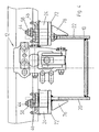
- Fig. 1
- eine Seitenansicht einer im Ausschnitt dargestellten Trogschwelle, teilweise geschnitten,
- Fig. 2
- eine Detaildarstellung eines der Fig. 1 zu entnehmenden Kippelementes zum Niederhalten einer Schienenbefestigungsplatte,
- Fig. 3
- das Kippelement nach Fig. 2 in Draufsicht,
- Fig. 4
- einen Querschnitt durch die Trogschwelle gemäß Fig. 1 und
- Fig. 5
- eine Draufsicht auf die Trogschwelle gemäß Fig. 1.
Claims (12)
- Vorrichtung zum Befestigen einer Schiene (16) mit Schienenfuß (28), insbesondere zum Befestigen bzw. Sichern einer Backenschiene oder Fahrschiene im Bereich einer Weiche oder Kreuzung, umfassend eine Lagerung (24) für die Schiene (16) und eine lösbar auf der Lagerung angeordnete und mit einem ersten Schienenfußschenkel der Schiene wechselwirkende Schienenbefestigungsplatte (18), wie Gleitstuhl oder Radlenkerfußplatte, wobei die Schienenbefestigungsplatte (18) über einen Niederhalter (26) gesichert ist, der sich unterhalb des Schienenfußes (28) und entlang diesem erstreckt sowie im Bereich des anderen zweiten Schienenfußschenkels (48) der Schiene (16) über ein erstes Befestigungselement (44) befestigt bzw. gesichert ist,
dadurch gekennzeichnet, dass der Niederhalter (26) ein sich unterhalb des Schienenfußes (28) erstreckendes und unterhalb des Schienenfußes kippbar gelagertes Element (26) ist, das über ein zweites Befestigungselement mit der Schienenbefestigungsplatte (18) verbunden ist. - Vorrichtung nach Anspruch 1,
dadurch gekennzeichnet, dass das kippbar gelagerte Element (26) ein Kippelement mit zwei Armen ist, dass einer der Arme von dem ersten Befestigungselement (44) durchsetzt ist, über das seinerseits ein den zur Schienenbefestigungsplatte (18) fernliegenden Schienenfußschenkel (48) der Schiene (16) niederhaltendes Spannelement (46) gesichert ist, und dass der andere Arm von einem zweiten von der Schienenbefestigungsplatte ausgehenden Verbindungselement (58) wie Zapfen oder Bolzen durchsetzt ist bzw. an der Schienenbefestigungsplatte (18) angelenkt ist - Vorrichtung nach Anspruch 1 oder 2,
dadurch gekennzeichnet, dass das zweite Befestigungselement (58) unterseitig von der Schienenbefestigungsplatte (18) ausgeht und vorzugsweise mit dieser verschraubt oder verschweißt ist. - Vorrichtung nach zumindest einem oder mehreren der vorhergehenden Ansprüche,
dadurch gekennzeichnet, dass das Kippelement (26) eine schienenfußseitig gekrümmt verlaufende Oberfläche mit einem vorzugsweise vom mittleren Bereich ausgehenden Vorsprung (32) als Abstützung aufweist, über die das Kippelement kippbar ist und/oder dass von dem Schienenfuß bzw. dessen Lagerung (24) ein sich in Richtung des Kippelementes (26) erstreckender Vorsprung als Abstützung für das Kippelement ausgeht. - Vorrichtung nach zumindest einem oder mehreren der vorhergehenden Ansprüche,
dadurch gekennzeichnet, dass das Kippelement (26) unterseitig einen kalottenförmigen Vorsprung (62) aufweist, der von dem ersten oder zweiten Befestigungselement (58) durchsetzt ist und abschnittsweise in ein das erste bzw. zweite Befestigungselement sicherndes Element wie Mutter (60) mit dem kalottenförmigen Vorsprung zumindest teilweise angepasster Innengeometrie eingreift. - Vorrichtung nach zumindest einem oder mehreren der vorhergehenden Ansprüche,
dadurch gekennzeichnet, dass das erste oder zweite Befestigungselement (46) ein Schraubenelement ist, wobei vorzugsweise dessen Kopf (50) unterseitig entlang des Kippelementes (26) verläuft und zwischen dem Kopf und der Unterseite (52) zwei Scheibenelemente (54, 56) mit aufeinanderliegenden einander angepassten gekrümmten Flächen angeordnet sind, die neigungsmäßig zueinander verschiebbar sind. - Vorrichtung nach zumindest einem oder mehreren der vorhergehenden Ansprüche,
dadurch gekennzeichnet, dass die Schienenbefestigungsplatte (18) schienenfußabgewandt an einem Anschlag wie Stufe (68) anliegt. - Vorrichtung nach zumindest einem oder mehreren der vorhergehenden Ansprüche,
dadurch gekennzeichnet, dass das Kippelement (26) im Bereich entlang einer Seitenwandung (20, 22) einer Kasten- oder Trogschwelle (10) verläuft, wobei insbesondere entlang einer jeden Seitenwandung der Trogschwelle eine Schienenbefestigungsplatte (18) mit jeweils zugeordnetem Kippelement (26) verläuft. - Vorrichtung nach zumindest einem oder mehreren der vorhergehenden Ansprüche,
dadurch gekennzeichnet, dass die Seitenwandung (20, 22) im Bereich des Kippelementes (26) eine Aussparung wie Ausschnitt (78) aufweist und/oder dass außenseitig an den Seitenwandungen (20, 22) und senkrecht zu diesen verlaufend Abstützungen wie Knotenbleche (76) vorgesehen wie angeschweißt sind, auf denen jeweils mittelbar oder unmittelbar eine Lagerung (24) lösbar angeordnet ist, wobei insbesondere vom Längsrand (74) der Seitenwandung (20, 22) und oberen Rand der Abstützung wie Knotenblech (76) ein Plattenelement wie Blech (72) ausgeht, auf dem die Lagerung (24) lösbar angeordnet ist. - Vorrichtung nach zumindest einem oder mehreren der vorhergehenden Ansprüche,
dadurch gekennzeichnet, dass das Plattenelement wie Blech (72) mit der Abstützung wie Knotenblech (76) und dem oberen Rand (74) der Seitenwandung (20, 22) verschweißt ist - Vorrichtung nach zumindest einem oder mehreren der vorhergehenden Ansprüche,
dadurch gekennzeichnet, dass die Lagerung über Befestigungselemente (70) mit dem Plattenelement wie Blech (72) verschraubt ist, wobei die Befestigungselemente abschnittsweise innerhalb von randseitigen Aussparungen wie Ausschnitten (80) der Seitenwandung (20, 22) verlaufen. - Vorrichtung nach zumindest einem oder mehreren der vorhergehenden Ansprüche,
dadurch gekennzeichnet, dass die vom jeweiligen Längsrand (74) der Seitenwandung (20, 22) ausgehenden Lagerungen (24) zueinander beabstandet sind und dass von der Trog- bzw. Kastenschwelle ausgehend und sich zumindest abschnittsweise zwischen den Lagerungen (24) erstreckend ein Weichenverschluss (12) verläuft.
Applications Claiming Priority (2)
| Application Number | Priority Date | Filing Date | Title |
|---|---|---|---|
| DE19841903 | 1998-09-11 | ||
| DE19841903A DE19841903A1 (de) | 1998-09-11 | 1998-09-11 | Vorrichtung zum Befestigen einer Schiene |
Publications (2)
| Publication Number | Publication Date |
|---|---|
| EP0985765A1 EP0985765A1 (de) | 2000-03-15 |
| EP0985765B1 true EP0985765B1 (de) | 2003-07-09 |
Family
ID=7880824
Family Applications (1)
| Application Number | Title | Priority Date | Filing Date |
|---|---|---|---|
| EP99117643A Expired - Lifetime EP0985765B1 (de) | 1998-09-11 | 1999-09-08 | Vorrichtung zum Befestigen einer Schiene |
Country Status (6)
| Country | Link |
|---|---|
| EP (1) | EP0985765B1 (de) |
| AT (1) | ATE244791T1 (de) |
| DE (2) | DE19841903A1 (de) |
| DK (1) | DK0985765T3 (de) |
| ES (1) | ES2204039T3 (de) |
| PT (1) | PT985765E (de) |
Families Citing this family (1)
| Publication number | Priority date | Publication date | Assignee | Title |
|---|---|---|---|---|
| DE102006021683A1 (de) * | 2006-05-10 | 2007-11-22 | SCHWIHAG GESELLSCHAFT FüR EISENBAHNOBERBAU MBH | Hohlkastenschwelle |
Family Cites Families (7)
| Publication number | Priority date | Publication date | Assignee | Title |
|---|---|---|---|---|
| DE3411122A1 (de) | 1984-03-26 | 1985-10-03 | BWG Butzbacher Weichenbau GmbH, 6308 Butzbach | Vorrichtung zum befestigen von schienen |
| DE4229014A1 (de) | 1992-09-02 | 1994-03-03 | Butzbacher Weichenbau Gmbh | Vorrichtung zum Befestigen einer Schiene |
| DE4315200C2 (de) * | 1993-05-07 | 2003-04-30 | Schwihag Gmbh | Querschwelle mit Verstellvorrichtung für Weichenzungen |
| FR2715412B1 (fr) * | 1994-01-21 | 1996-04-12 | Sncf | Dispositif de montage d'une aiguille et d'un contre-aiguille sur une traverse; base formant coussinet ou platine de glissement ou d'aiguille et ressort de flexion formant partie d'un tel dispositif. |
| DE4405135A1 (de) * | 1994-02-18 | 1995-08-24 | Butzbacher Weichenbau Gmbh | Schienenbefestigung |
| DE19545341A1 (de) * | 1995-12-05 | 1997-06-12 | Butzbacher Weichenbau Gmbh | Gleitstuhl |
| DE19545342A1 (de) | 1995-12-05 | 1997-06-12 | Butzbacher Weichenbau Gmbh | Anordnung von Schwellen für Schienen |
-
1998
- 1998-09-11 DE DE19841903A patent/DE19841903A1/de not_active Withdrawn
-
1999
- 1999-09-08 ES ES99117643T patent/ES2204039T3/es not_active Expired - Lifetime
- 1999-09-08 DK DK99117643T patent/DK0985765T3/da active
- 1999-09-08 EP EP99117643A patent/EP0985765B1/de not_active Expired - Lifetime
- 1999-09-08 PT PT99117643T patent/PT985765E/pt unknown
- 1999-09-08 DE DE59906244T patent/DE59906244D1/de not_active Expired - Lifetime
- 1999-09-08 AT AT99117643T patent/ATE244791T1/de not_active IP Right Cessation
Also Published As
| Publication number | Publication date |
|---|---|
| PT985765E (pt) | 2003-11-28 |
| ATE244791T1 (de) | 2003-07-15 |
| DK0985765T3 (da) | 2003-11-03 |
| DE59906244D1 (de) | 2003-08-14 |
| EP0985765A1 (de) | 2000-03-15 |
| DE19841903A1 (de) | 2000-03-16 |
| ES2204039T3 (es) | 2004-04-16 |
Similar Documents
| Publication | Publication Date | Title |
|---|---|---|
| DE69320593T2 (de) | Knochenplattensystem | |
| EP0836981B1 (de) | Vorrichtung an einer Lenksäule für Kraftfahrzeuge zur Längen- und Neigungsverstellung | |
| EP0535315B1 (de) | Wirbelkörperplatzhalter | |
| WO2005124025A1 (de) | Anordnung zum befestigen einer schiene | |
| EP2191069B1 (de) | System zum befestigen einer schiene und spannklemme für ein solches system | |
| WO2004065692A1 (de) | Spindelvorrichtung zur höhenverstellung von gleisrosten | |
| EP1974100A1 (de) | System zur befestigung einer schiene | |
| DE20006335U1 (de) | Verbindungseinheit zum winkeleinstellbaren Verbinden mindestens zweier Lautsprecherboxen und entsprechend verbundene Lautsprecherboxen | |
| DE2626808C2 (de) | Vorrichtung zum Befestigen eines Plattenteils an einem Basisteil | |
| DE60003962T2 (de) | Befestigung einer Spurplatte an einer Abzweigung | |
| DE69929707T2 (de) | Ein mit befestigungsvorrichtung(en) zusammengesetzter aufzug | |
| EP0016338B1 (de) | Spannvorrichtung für eine Druckplatte zur Durchführung einer Druckosteosynthese | |
| DE10157676A1 (de) | Einrichtung zum seitlichen Abstützen einer Schiene | |
| EP0338124A2 (de) | Fahrbahnübergang | |
| EP0985765A1 (de) | Vorrichtung zum Befestigen einer Schiene | |
| DE10139198A1 (de) | Befestigung einer in einen Schienenweg eingebauten Weiche auf einem Oberbau | |
| DE102009029074B4 (de) | Schwingungsabsorberanordnung | |
| DE3817566A1 (de) | Unterlagplatte zum befestigen einer schiene | |
| DE29707871U1 (de) | Dachtritteinheit | |
| EP0690940B1 (de) | Schienenanordnung | |
| DE10208729A1 (de) | Oberflächenentwässerungs-Einrichtung | |
| DE202019104884U1 (de) | Beschlagelement und Beschlagsatz für eine Fahrbahnplatte, sowie Fahrbahnplatte | |
| DE4212679A1 (de) | Anordnung einer Schiene | |
| EP3870756B1 (de) | Abstützung für eine schiene | |
| EP4283040A1 (de) | Anordnung zum niederhalten einer schiene |
Legal Events
| Date | Code | Title | Description |
|---|---|---|---|
| PUAI | Public reference made under article 153(3) epc to a published international application that has entered the european phase |
Free format text: ORIGINAL CODE: 0009012 |
|
| AK | Designated contracting states |
Kind code of ref document: A1 Designated state(s): AT BE CH CY DE DK ES FI FR GB GR IE IT LI LU MC NL PT SE |
|
| AX | Request for extension of the european patent |
Free format text: AL;LT;LV;MK;RO;SI |
|
| 17P | Request for examination filed |
Effective date: 20000318 |
|
| RIN1 | Information on inventor provided before grant (corrected) |
Inventor name: KUNITZ, WALTER, DR. Inventor name: SCHMEDDERS, STEFAN, DIPL.-ING. Inventor name: DIETZE, HANS-ULRICH, DR. |
|
| AKX | Designation fees paid |
Free format text: AT BE CH DE DK ES FI FR GB LI LU NL SE |
|
| RBV | Designated contracting states (corrected) |
Designated state(s): AT BE CH CY DE DK ES FI FR GB GR IE IT LI LU MC NL PT SE |
|
| RAP1 | Party data changed (applicant data changed or rights of an application transferred) |
Owner name: BWG GMBH & CO. KG |
|
| GRAH | Despatch of communication of intention to grant a patent |
Free format text: ORIGINAL CODE: EPIDOS IGRA |
|
| RTI1 | Title (correction) |
Free format text: DEVICE FOR FIXING A RAIL |
|
| RAP1 | Party data changed (applicant data changed or rights of an application transferred) |
Owner name: VAE AKTIENGESELLSCHAFT Owner name: BWG GMBH & CO. KG |
|
| GRAH | Despatch of communication of intention to grant a patent |
Free format text: ORIGINAL CODE: EPIDOS IGRA |
|
| RAP1 | Party data changed (applicant data changed or rights of an application transferred) |
Owner name: VAE GMBH Owner name: BWG GMBH & CO. KG |
|
| GRAA | (expected) grant |
Free format text: ORIGINAL CODE: 0009210 |
|
| AK | Designated contracting states |
Designated state(s): AT BE CH CY DE DK ES FI FR GB GR IE IT LI LU MC NL PT SE |
|
| PG25 | Lapsed in a contracting state [announced via postgrant information from national office to epo] |
Ref country code: IE Free format text: LAPSE BECAUSE OF FAILURE TO SUBMIT A TRANSLATION OF THE DESCRIPTION OR TO PAY THE FEE WITHIN THE PRESCRIBED TIME-LIMIT Effective date: 20030709 |
|
| REG | Reference to a national code |
Ref country code: GB Ref legal event code: FG4D Free format text: NOT ENGLISH |
|
| REG | Reference to a national code |
Ref country code: CH Ref legal event code: EP |
|
| REF | Corresponds to: |
Ref document number: 59906244 Country of ref document: DE Date of ref document: 20030814 Kind code of ref document: P |
|
| REG | Reference to a national code |
Ref country code: IE Ref legal event code: FG4D Free format text: GERMAN |
|
| PG25 | Lapsed in a contracting state [announced via postgrant information from national office to epo] |
Ref country code: CY Free format text: LAPSE BECAUSE OF FAILURE TO SUBMIT A TRANSLATION OF THE DESCRIPTION OR TO PAY THE FEE WITHIN THE PRESCRIBED TIME-LIMIT Effective date: 20030908 |
|
| PG25 | Lapsed in a contracting state [announced via postgrant information from national office to epo] |
Ref country code: MC Free format text: LAPSE BECAUSE OF NON-PAYMENT OF DUE FEES Effective date: 20030930 |
|
| REG | Reference to a national code |
Ref country code: SE Ref legal event code: TRGR Ref country code: CH Ref legal event code: NV Representative=s name: LONZA A.G. |
|
| REG | Reference to a national code |
Ref country code: GR Ref legal event code: EP Ref document number: 20030403846 Country of ref document: GR |
|
| REG | Reference to a national code |
Ref country code: DK Ref legal event code: T3 |
|
| GBT | Gb: translation of ep patent filed (gb section 77(6)(a)/1977) |
Effective date: 20031112 |
|
| REG | Reference to a national code |
Ref country code: IE Ref legal event code: FD4D |
|
| ET | Fr: translation filed | ||
| REG | Reference to a national code |
Ref country code: ES Ref legal event code: FG2A Ref document number: 2204039 Country of ref document: ES Kind code of ref document: T3 |
|
| PLBE | No opposition filed within time limit |
Free format text: ORIGINAL CODE: 0009261 |
|
| STAA | Information on the status of an ep patent application or granted ep patent |
Free format text: STATUS: NO OPPOSITION FILED WITHIN TIME LIMIT |
|
| 26N | No opposition filed |
Effective date: 20040414 |
|
| PGFP | Annual fee paid to national office [announced via postgrant information from national office to epo] |
Ref country code: PT Payment date: 20060831 Year of fee payment: 8 |
|
| PGFP | Annual fee paid to national office [announced via postgrant information from national office to epo] |
Ref country code: FI Payment date: 20060914 Year of fee payment: 8 Ref country code: CH Payment date: 20060914 Year of fee payment: 8 Ref country code: AT Payment date: 20060914 Year of fee payment: 8 |
|
| PGFP | Annual fee paid to national office [announced via postgrant information from national office to epo] |
Ref country code: DK Payment date: 20060915 Year of fee payment: 8 |
|
| PGFP | Annual fee paid to national office [announced via postgrant information from national office to epo] |
Ref country code: LU Payment date: 20060921 Year of fee payment: 8 Ref country code: GB Payment date: 20060921 Year of fee payment: 8 |
|
| PGFP | Annual fee paid to national office [announced via postgrant information from national office to epo] |
Ref country code: GR Payment date: 20060925 Year of fee payment: 8 |
|
| PGFP | Annual fee paid to national office [announced via postgrant information from national office to epo] |
Ref country code: IT Payment date: 20060930 Year of fee payment: 8 |
|
| PGFP | Annual fee paid to national office [announced via postgrant information from national office to epo] |
Ref country code: BE Payment date: 20061012 Year of fee payment: 8 |
|
| PGFP | Annual fee paid to national office [announced via postgrant information from national office to epo] |
Ref country code: SE Payment date: 20060914 Year of fee payment: 8 |
|
| REG | Reference to a national code |
Ref country code: PT Ref legal event code: MM4A Free format text: LAPSE DUE TO NON-PAYMENT OF FEES Effective date: 20080310 |
|
| BERE | Be: lapsed |
Owner name: *VAE G.M.B.H. Effective date: 20070930 Owner name: *BWG G.M.B.H. & CO. K.G. Effective date: 20070930 |
|
| PG25 | Lapsed in a contracting state [announced via postgrant information from national office to epo] |
Ref country code: SE Free format text: LAPSE BECAUSE OF NON-PAYMENT OF DUE FEES Effective date: 20070909 |
|
| REG | Reference to a national code |
Ref country code: DK Ref legal event code: EBP |
|
| REG | Reference to a national code |
Ref country code: CH Ref legal event code: PL |
|
| EUG | Se: european patent has lapsed | ||
| GBPC | Gb: european patent ceased through non-payment of renewal fee |
Effective date: 20070908 |
|
| PG25 | Lapsed in a contracting state [announced via postgrant information from national office to epo] |
Ref country code: PT Free format text: LAPSE BECAUSE OF NON-PAYMENT OF DUE FEES Effective date: 20080310 Ref country code: FI Free format text: LAPSE BECAUSE OF NON-PAYMENT OF DUE FEES Effective date: 20070908 |
|
| PG25 | Lapsed in a contracting state [announced via postgrant information from national office to epo] |
Ref country code: AT Free format text: LAPSE BECAUSE OF NON-PAYMENT OF DUE FEES Effective date: 20070908 |
|
| PG25 | Lapsed in a contracting state [announced via postgrant information from national office to epo] |
Ref country code: LI Free format text: LAPSE BECAUSE OF NON-PAYMENT OF DUE FEES Effective date: 20070930 Ref country code: CH Free format text: LAPSE BECAUSE OF NON-PAYMENT OF DUE FEES Effective date: 20070930 |
|
| PG25 | Lapsed in a contracting state [announced via postgrant information from national office to epo] |
Ref country code: BE Free format text: LAPSE BECAUSE OF NON-PAYMENT OF DUE FEES Effective date: 20070930 |
|
| PG25 | Lapsed in a contracting state [announced via postgrant information from national office to epo] |
Ref country code: DK Free format text: LAPSE BECAUSE OF NON-PAYMENT OF DUE FEES Effective date: 20071001 |
|
| PG25 | Lapsed in a contracting state [announced via postgrant information from national office to epo] |
Ref country code: GB Free format text: LAPSE BECAUSE OF NON-PAYMENT OF DUE FEES Effective date: 20070908 |
|
| PG25 | Lapsed in a contracting state [announced via postgrant information from national office to epo] |
Ref country code: GR Free format text: LAPSE BECAUSE OF NON-PAYMENT OF DUE FEES Effective date: 20080402 |
|
| PG25 | Lapsed in a contracting state [announced via postgrant information from national office to epo] |
Ref country code: LU Free format text: LAPSE BECAUSE OF NON-PAYMENT OF DUE FEES Effective date: 20070908 Ref country code: IT Free format text: LAPSE BECAUSE OF NON-PAYMENT OF DUE FEES Effective date: 20070908 |
|
| REG | Reference to a national code |
Ref country code: FR Ref legal event code: PLFP Year of fee payment: 18 |
|
| REG | Reference to a national code |
Ref country code: FR Ref legal event code: PLFP Year of fee payment: 19 |
|
| REG | Reference to a national code |
Ref country code: FR Ref legal event code: PLFP Year of fee payment: 20 |
|
| PGFP | Annual fee paid to national office [announced via postgrant information from national office to epo] |
Ref country code: FR Payment date: 20180924 Year of fee payment: 20 Ref country code: DE Payment date: 20180920 Year of fee payment: 20 |
|
| PGFP | Annual fee paid to national office [announced via postgrant information from national office to epo] |
Ref country code: NL Payment date: 20180919 Year of fee payment: 20 |
|
| PGFP | Annual fee paid to national office [announced via postgrant information from national office to epo] |
Ref country code: ES Payment date: 20181022 Year of fee payment: 20 |
|
| REG | Reference to a national code |
Ref country code: DE Ref legal event code: R071 Ref document number: 59906244 Country of ref document: DE |
|
| REG | Reference to a national code |
Ref country code: NL Ref legal event code: MK Effective date: 20190907 |
|
| REG | Reference to a national code |
Ref country code: ES Ref legal event code: FD2A Effective date: 20220104 |
|
| PG25 | Lapsed in a contracting state [announced via postgrant information from national office to epo] |
Ref country code: ES Free format text: LAPSE BECAUSE OF EXPIRATION OF PROTECTION Effective date: 20190909 |