EP0983183B1 - Kraftfahrzeug-rahmenaufbau - Google Patents
Kraftfahrzeug-rahmenaufbau Download PDFInfo
- Publication number
- EP0983183B1 EP0983183B1 EP99910767A EP99910767A EP0983183B1 EP 0983183 B1 EP0983183 B1 EP 0983183B1 EP 99910767 A EP99910767 A EP 99910767A EP 99910767 A EP99910767 A EP 99910767A EP 0983183 B1 EP0983183 B1 EP 0983183B1
- Authority
- EP
- European Patent Office
- Prior art keywords
- filler material
- frame
- cross
- mpa
- section
- Prior art date
- Legal status (The legal status is an assumption and is not a legal conclusion. Google has not performed a legal analysis and makes no representation as to the accuracy of the status listed.)
- Expired - Lifetime
Links
- 239000000463 material Substances 0.000 claims abstract description 433
- 239000000945 filler Substances 0.000 claims abstract description 406
- 238000005452 bending Methods 0.000 claims abstract description 128
- 230000001070 adhesive effect Effects 0.000 claims description 64
- 239000000853 adhesive Substances 0.000 claims description 62
- 230000003014 reinforcing effect Effects 0.000 claims description 57
- 238000000034 method Methods 0.000 claims description 54
- 230000008569 process Effects 0.000 claims description 52
- 239000003822 epoxy resin Substances 0.000 claims description 48
- 229920000647 polyepoxide Polymers 0.000 claims description 48
- 238000004070 electrodeposition Methods 0.000 claims description 34
- 238000010008 shearing Methods 0.000 claims description 27
- 239000012790 adhesive layer Substances 0.000 claims description 24
- 239000010410 layer Substances 0.000 claims description 24
- 239000007788 liquid Substances 0.000 claims description 15
- 238000000151 deposition Methods 0.000 claims description 3
- 230000008021 deposition Effects 0.000 claims description 3
- 238000007599 discharging Methods 0.000 claims description 3
- 230000008878 coupling Effects 0.000 claims 1
- 238000010168 coupling process Methods 0.000 claims 1
- 238000005859 coupling reaction Methods 0.000 claims 1
- 230000002787 reinforcement Effects 0.000 description 65
- 238000010521 absorption reaction Methods 0.000 description 63
- 238000012360 testing method Methods 0.000 description 40
- 230000001965 increasing effect Effects 0.000 description 31
- 230000003068 static effect Effects 0.000 description 26
- 238000005187 foaming Methods 0.000 description 23
- 230000004048 modification Effects 0.000 description 20
- 238000012986 modification Methods 0.000 description 20
- 229920006395 saturated elastomer Polymers 0.000 description 19
- 229910000831 Steel Inorganic materials 0.000 description 16
- 239000010959 steel Substances 0.000 description 16
- 239000002023 wood Substances 0.000 description 16
- 238000013001 point bending Methods 0.000 description 15
- 239000006260 foam Substances 0.000 description 12
- JOYRKODLDBILNP-UHFFFAOYSA-N Ethyl urethane Chemical compound CCOC(N)=O JOYRKODLDBILNP-UHFFFAOYSA-N 0.000 description 11
- 229920005989 resin Polymers 0.000 description 10
- 239000011347 resin Substances 0.000 description 10
- 238000006073 displacement reaction Methods 0.000 description 9
- 238000001035 drying Methods 0.000 description 9
- 230000006872 improvement Effects 0.000 description 9
- 230000000694 effects Effects 0.000 description 8
- 230000009471 action Effects 0.000 description 5
- 235000008331 Pinus X rigitaeda Nutrition 0.000 description 4
- 241000018646 Pinus brutia Species 0.000 description 4
- 235000011613 Pinus brutia Nutrition 0.000 description 4
- 238000010586 diagram Methods 0.000 description 3
- 239000011148 porous material Substances 0.000 description 3
- 239000000523 sample Substances 0.000 description 3
- 229910052782 aluminium Inorganic materials 0.000 description 2
- XAGFODPZIPBFFR-UHFFFAOYSA-N aluminium Chemical compound [Al] XAGFODPZIPBFFR-UHFFFAOYSA-N 0.000 description 2
- 230000008901 benefit Effects 0.000 description 2
- 238000005336 cracking Methods 0.000 description 2
- 230000007423 decrease Effects 0.000 description 2
- 238000009792 diffusion process Methods 0.000 description 2
- 239000000446 fuel Substances 0.000 description 2
- 238000007689 inspection Methods 0.000 description 2
- 238000003754 machining Methods 0.000 description 2
- 238000004519 manufacturing process Methods 0.000 description 2
- 238000005259 measurement Methods 0.000 description 2
- 238000010422 painting Methods 0.000 description 2
- 239000005011 phenolic resin Substances 0.000 description 2
- 238000003825 pressing Methods 0.000 description 2
- 230000009467 reduction Effects 0.000 description 2
- 238000003466 welding Methods 0.000 description 2
- 240000005109 Cryptomeria japonica Species 0.000 description 1
- 101710153181 Protein PYRICULARIA ORYZAE RESISTANCE 21 Proteins 0.000 description 1
- 239000011324 bead Substances 0.000 description 1
- 238000006243 chemical reaction Methods 0.000 description 1
- 239000004927 clay Substances 0.000 description 1
- 239000011248 coating agent Substances 0.000 description 1
- 238000000576 coating method Methods 0.000 description 1
- 230000006835 compression Effects 0.000 description 1
- 238000007906 compression Methods 0.000 description 1
- 238000012669 compression test Methods 0.000 description 1
- 230000001419 dependent effect Effects 0.000 description 1
- 230000002708 enhancing effect Effects 0.000 description 1
- 238000005470 impregnation Methods 0.000 description 1
- 238000011835 investigation Methods 0.000 description 1
- 229910052751 metal Inorganic materials 0.000 description 1
- 239000002184 metal Substances 0.000 description 1
- 150000002739 metals Chemical class 0.000 description 1
- 239000000203 mixture Substances 0.000 description 1
- 229910001220 stainless steel Inorganic materials 0.000 description 1
- 239000010935 stainless steel Substances 0.000 description 1
- 229920002803 thermoplastic polyurethane Polymers 0.000 description 1
- 229920001187 thermosetting polymer Polymers 0.000 description 1
- 238000009423 ventilation Methods 0.000 description 1
- 125000000391 vinyl group Chemical group [H]C([*])=C([H])[H] 0.000 description 1
- 229920002554 vinyl polymer Polymers 0.000 description 1
- 239000013585 weight reducing agent Substances 0.000 description 1
Images


Classifications
-
- B—PERFORMING OPERATIONS; TRANSPORTING
- B62—LAND VEHICLES FOR TRAVELLING OTHERWISE THAN ON RAILS
- B62D—MOTOR VEHICLES; TRAILERS
- B62D29/00—Superstructures, understructures, or sub-units thereof, characterised by the material thereof
-
- B—PERFORMING OPERATIONS; TRANSPORTING
- B60—VEHICLES IN GENERAL
- B60J—WINDOWS, WINDSCREENS, NON-FIXED ROOFS, DOORS, OR SIMILAR DEVICES FOR VEHICLES; REMOVABLE EXTERNAL PROTECTIVE COVERINGS SPECIALLY ADAPTED FOR VEHICLES
- B60J5/00—Doors
- B60J5/04—Doors arranged at the vehicle sides
- B60J5/042—Reinforcement elements
- B60J5/0422—Elongated type elements, e.g. beams, cables, belts or wires
- B60J5/0438—Elongated type elements, e.g. beams, cables, belts or wires characterised by the type of elongated elements
- B60J5/0443—Beams
-
- B—PERFORMING OPERATIONS; TRANSPORTING
- B29—WORKING OF PLASTICS; WORKING OF SUBSTANCES IN A PLASTIC STATE IN GENERAL
- B29C—SHAPING OR JOINING OF PLASTICS; SHAPING OF MATERIAL IN A PLASTIC STATE, NOT OTHERWISE PROVIDED FOR; AFTER-TREATMENT OF THE SHAPED PRODUCTS, e.g. REPAIRING
- B29C64/00—Additive manufacturing, i.e. manufacturing of three-dimensional [3D] objects by additive deposition, additive agglomeration or additive layering, e.g. by 3D printing, stereolithography or selective laser sintering
- B29C64/40—Structures for supporting 3D objects during manufacture and intended to be sacrificed after completion thereof
-
- B—PERFORMING OPERATIONS; TRANSPORTING
- B62—LAND VEHICLES FOR TRAVELLING OTHERWISE THAN ON RAILS
- B62D—MOTOR VEHICLES; TRAILERS
- B62D25/00—Superstructure or monocoque structure sub-units; Parts or details thereof not otherwise provided for
- B62D25/04—Door pillars ; windshield pillars
-
- B—PERFORMING OPERATIONS; TRANSPORTING
- B62—LAND VEHICLES FOR TRAVELLING OTHERWISE THAN ON RAILS
- B62D—MOTOR VEHICLES; TRAILERS
- B62D29/00—Superstructures, understructures, or sub-units thereof, characterised by the material thereof
- B62D29/001—Superstructures, understructures, or sub-units thereof, characterised by the material thereof characterised by combining metal and synthetic material
- B62D29/002—Superstructures, understructures, or sub-units thereof, characterised by the material thereof characterised by combining metal and synthetic material a foamable synthetic material or metal being added in situ
Definitions
- the present invention relates to a frame structure for vehicle bodies of, for example, automobiles, and more specifically, a frame structure for a vehicle body in which a filler material is filled in at least part of the frame cross section.
- WO 97/09134 relates to a reinforced formed part, according to the preamble of claim 1, with longitudinal and/or transverse cross-sections which may differ in shape and/or size, with a hollow outer formed part and a highly deformation-resistant open or closed-cell foam filling which is at least partly adjacent to the outer formed part, at least partly fills the inner space in the hollow outer formed part and improves the mechanical deformation resistance of the outer formed part and a process for producing the formed part.
- Japanese Patent Laid-Open Publication HEI 3-32990 discloses a structure in which for a simple and reliable accomplishment of a process of filling urethane foam into the cross section of the frame (center pillar), air vent holes are provided at connecting portions of the center pillar with roof side rails.
- a filler material When a filler material is filled into the frame cross section for enhancement in the energy absorbancy of the frame at collisions as described above, it has conventionally been practiced to use a filler material having a high deformability above a certain level against action of collision loads, such as urethane foam, so as to implement energy absorption by deformation of the frame including such a filler material.
- a filler material having a high deformability above a certain level against action of collision loads such as urethane foam
- the present inventor has found it difficult to attain a sufficient improvement in the energy absorbancy of the frame when the filler material is low in strength and too deformation-prone like urethane foam.
- the reason of this is that when a material having a high deformability like urethane foam is used as the filler material as it has been conventionally, collision loads are hardly be sufficiently dispersed and transferred from a load input point to its surrounding frame steel plate, and the frame is largely deformed locally only at the load input point and its vicinities.
- a frame structure for vehicle bodies in which a filler material is filled in at least part of a cross section of the frame, wherein the filler material has a mean compressive strength set to not less than 4 MPa and a maximum bending strength set to not less than 10 MPa.
- the above setting for the filler material that the mean compressive strength is not less than 4 MPa or the maximum bending strength is not less than 10 MPa is due to the following reason.
- the degree of increase in the energy absorption amount is saturated when the mean compressive strength becomes 4 MPa or more. In other words, if the mean compressive strength is 4 MPa or more, an energy absorption amount approximately close to a maximum value can be obtained. Still, whereas the energy absorption amount increases with increasing maximum bending strength of the filler material, the degree of increase in the energy absorption amount is saturated when the maximum bending strength becomes 10 MPa or more. In other words, if the maximum bending strength is 10 MPa or more, an energy absorption amount approximately close to a maximum value can be obtained.
- the mean compressive strength is defined for a collision load input side, while the maximum bending strength is defined for a counter collision load input side, and a reinforcing member is disposed on the counter collision load input side of the filler material.
- the setting for the filler material that the mean compressive strength is not less than 4 MPa or the maximum bending strength is not less than 10 MPa is due to the following reason.
- the degree of increase in the energy absorption amount is saturated when the mean compressive strength becomes 4 MPa or more. In other words, if the mean compressive strength is 4 MPa or more, an energy absorption amount approximately close to a maximum value can be obtained. Otherwise, whereas the energy absorption amount increases with increasing maximum bending strength of the filler material, the degree of increase in the energy absorption amount is saturated when the maximum bending strength becomes 10 MPa or more. In other words, if the maximum bending strength is 10 MPa or more, an energy absorption amount approximately close to a maximum value can be obtained.
- the filler material has a mean compressive strength set to not less than 5 MPa or a maximum bending strength set to not less than 60 MPa.
- the above setting for the filler material that the mean compressive strength is not less than 5 MPa or the maximum bending strength is not less than 60 MPa is due to the following reason.
- the mean compressive strength of the filler material is 5 MPa or more in particular, the degree of increase in the energy absorption amount of the frame is saturated more stably, so that an energy absorption amount close to the maximum value can be obtained more stably.
- the maximum bending strength of the filler material is 60 MPa or more in particular, the degree of increase in the energy absorption amount of the frame is saturated more stably, so that an energy absorption amount close to the maximum value can be obtained more stably.
- the filler material has a mean compressive strength set to not less than 5 MPa and a maximum bending strength set to not less than 60 MPa.
- the above setting for the filler material that the mean compressive strength is not less than 5 MPa and the maximum bending strength is not less than 60 MPa is due to the following reason.
- the mean compressive strength of the filler material is 5 MPa or more in particular, the degree of increase in the energy absorption amount of the frame is saturated more stably, so that an energy absorption amount close to the maximum value can be obtained more stably.
- the maximum bending strength of the filler material is 60 MPa or more in particular, the degree of increase in the energy absorption amount of the frame is saturated more stably, so that an energy absorption amount close to the maximum value can be obtained more stably.
- different filler materials having the characteristics are disposed in a form of a multilayer structure.
- the filler material has a density set to not more than 1.0 g/cm 3 .
- the above setting for the filler material that the density is not more than 1.0 g/cm 3 is because densities beyond 1.0 g/cm 3 are undesirable in terms of weight reduction and cost, comparing with the cases in which a reinforcement is provided in the frame cross section.
- the filler material is made of a porous material.
- the porous material includes not only foamable materials but also such various materials having porosity as sintered bodies of metals or the like, press hardened wood chips, and mixtures with hollow beads.
- the filler material is epoxy resin.
- the filler material is filled over a range of 15% or more of a length between load fulcrums of the frame.
- the above setting for the filler material that the filling range of the filler material is 15% or more of a length between load fulcrums of the frame is based on the ground that the absorbed energy increases with increasing range of filling length of the filler material, but is saturated at about 15%. In other words, if the filling length range of the filler material is 15% or more, then a nearly maximum energy absorption amount can be obtained.
- a reinforcing member for reinforcing the frame and/or the filler material is disposed in at least part of the frame cross section, and the reinforcing member has a holding function for holding the filler material.
- a discharge hole for discharging electrodeposition liquid from the frame cross section and/or the portion of the filler material deposition in an electrodeposition process of a panel member constituting the frame cross section.
- an adhesive layer is provided between at least part of the panel member constituting the frame cross section and filler material layer.
- the adhesive layer is provided between the collision load input side of the filler material and at least part of the panel member.
- the adhesive layer has a shearing adhesive strength of not less than 3 MPa.
- the shearing adhesive strength of the adhesive layer is not less than 3 MPa is based on the ground that whereas the maximum bending moment bearable for the frame increases with increasing shearing adhesive strength of the adhesive layer, the degree of increase in the maximum bending moment becomes gentler than before when the shearing adhesive strength becomes 3 MPa or more. In other words, if the shearing adhesive strength is 3 MPa or more, the maximum bending moment bearable for the frame can be increased quite effectively, so that a high energy absorbability can be obtained.
- the frame structure has the characteristics and the filler material itself has a shearing adhesive strength of not less than 3 MPa.
- the shearing adhesive strength of the filler material itself is not less than 3 MPa is based on the ground that whereas the maximum bending moment bearable for the frame increases with increasing shearing adhesive strength, the degree of increase in the maximum bending moment becomes gentler than before when the shearing adhesive strength becomes 3 MPa or more. In other words, if the shearing adhesive strength is 3 MPa or more, the maximum bending moment bearable for the frame can be increased quite effectively, so that a high energy absorbability can be obtained.
- the holes of the porosity are formed independently, whereby closeness of the adhesive is enhanced.
- the vehicle-body frame is applied to at least any one of a pillar member extending vertically in side portions of a vehicle body of an automobile, a frame member extending back and forth on both sides of a vehicle body of an automobile, a connecting member for connecting the frame members on right and left to each other, a reinforcing member of a door body, and a reinforcing member of bumpers.
- the pillar member includes a so-called center pillar, front pillar, hinge pillar portion and rear pillar which extend vertically in vehicle-body side portions of an automobile
- the frame member includes a so-called side sill, rear side frame and front frame which extend back and forth on both sides of a vehicle body of an automobile
- the connecting member includes a so-called cross member which connect the frame members on right and left to each other
- the reinforcing member of a door body includes a so-called impact bar
- the reinforcing member of bumpers includes a so-called bumper reinforcement.
- filler material itself i.e., not about a state that the filler material is filled into a cross section of the frame, but about the filler material itself
- its basic physical and mechanical characteristics were determined. More specifically, as to six types of materials shown in Table 1, densities were determined for the materials, respectively, and besides compressive strength and bending strength for each of the densities was determined by a test. It is to be noted that the density was given by a value at room temperature (about 20°C) in all the cases of the materials.
- the density of the reinforcement was calculated from both the weight of a reinforcement disposed in the frame cross section as shown in Fig. 7, which is later described, and the capacity of a portion of the frame corresponding to the part at which the reinforcement is placed, as an in-frame conversion density.
- the mean compressive strength of urethane foam, as well as the mean compressive strength and maximum bending strength of the reinforcement were unable to be measured because of excessively low values.
- test pieces were prepared by machining a sample material of each material into a cube with one side 30 mm long. With a compressive load applied to these sample materials in one direction, as schematically shown in Fig. 3, a mean load was determined within the amount of displacement (amount of compression) ranging from 0 to 8 mm and taken as the compressive strength (mean compressive strength) of the relevant filler material.
- test pieces were prepared by machining a sample material of each material into a 5 cm wide ⁇ 15 cm long ⁇ 1 cm thick flat plate.
- the test piece of each filler material was subjected to a three-point bending test with a fulcrum-to-fulcrum distance of 8 cm by the so-called auto graph. Then, from the resulting load - displacement diagram, the bending strength of each filler material was calculated.
- the density of a filler material to be filled into the frame cross section of the vehicle-body frame is properly not more than 1.0 g/cm 3 , and preferably, densities not more than 0.6 g/cm 3 allows further reduction effects in the weight to be expected.
- the filler materials of Table 1 were filled into the interior space in a specified portion of the frame FR, and subjected to various mechanical tests to examine the relationship between compressive strength or bending strength and energy absorbancy.
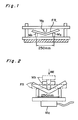
- FIG. 1 is an explanatory view schematically illustrating test equipment for conducting the static three-point bending test of the frame FR.
- Fig. 6 is an explanatory view showing, under magnification, an essential part of this static three-point bending test equipment.
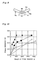
- Fig. 10 represents the relationship between filler material weight and energy absorption amount.
- black circles (•) denote a case in which wood was filled
- black squares ( ⁇ ) denote a case in which epoxy resin A was filled
- white triangles ( ⁇ ) denote a case in which a steel plate reinforcement (with plate thickness 1.0 mm) is provided in the frame cross section.
- a white circle (o) denotes by way of reference a case of a steel plate (SPC1-N) with plate thickness 1.6 mm.
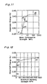
- Fig. 11 shows the relationship between the mean compressive strength of the filler material S and the amount of energy absorption, where the horizontal axis of the graph represents a logarithmic scale.
- the filling length Ef of each filler material S was set to 50 mm. With the filling length below this level, the filler material S would be subject to almost no bending effect, so that its energy absorbancy comes to have an intenser correlation with the compressive strength.
- points labeled a1, a2, a3, a4 and a5 show that data are attributed to urethane resin, Al foaming body, wood, epoxy resin A, and Al ingot, respectively.
- the degree of increase in the energy absorption amount of the frame FR is saturated more stably, so that an energy absorption amount close to the maximum value can be obtained more stably.
- Fig. 12 represents the relationship between the maximum bending strength of the filler material S and the energy absorption amount.
- Fig. 13 is a graph showing, under magnification, a part of the graph of Fig. 12 with the maximum bending strength below 80 MPa.
- the filling length Ef of each filler material S was set to 100 mm. With the filling length increased to around 100 mm, the bending strength of the filler material S comes to also contribute to an improvement in the energy absorbancy of the frame FR.
- points labeled b1, b2, b3, b4 and b5 show that data are attributed to Al foaming body, epoxy resin A, wood and Al ingot, respectively.
- the degree of increase in the energy absorption amount of the frame FR is saturated more stably, so that an energy absorption amount close to the maximum value can be obtained more stably.
- the energy absorption amount of the filler material S alone was determined as 7% or lower of the total absorbed energy. From this fact also, it can be understood that the load diffusion effect of the filler material S rather than the energy absorbancy of the filler material S itself quite largely contributes to the improvement in energy absorbancy attributable to the filling of the filler material S into the frame FR.
- the compressive strength of the filler material S contributes largely.
- the energy absorption amount increases with increasing mean compressive strength of the filler material S, and is saturated at about 4 MPa and more stably saturated at about 5 MPa (see Fig. 11).
- the crush of the cross section largely affects the energy absorption performance of the frame, where a crush of the cross section causes stress concentration, accelerating local deformation and incurring fracture of the frame FR, so that a sufficient energy absorption amount can be secured.
- the compressive load onto the filler material S filled in the frame FR directly acts particularly on the load input side. Therefore, the mean compressive strength of the filler material S is preferably maintained at enough value (4 MPa or more) to prevent any crush of the cross section particularly on the load input side.
- the bending load onto the filler material S filled in the frame FR directly acts particularly on the counter load input side. Therefore, the maximum bending strength of the filler material S is preferably maintained at enough value (10 MPa or more) to prevent any crack of the filler material particularly on the counter load input side.
- the energy absorbancy of the frame FR can be enhanced with great efficiency by making the filler material S into a multilayer structure composed of different filler materials, in which structure a filler material layer with the mean compressive strength not less than a specified value (at least 4 MPa) is provided on the load input side while a filler material layer with the maximum bending strength not less than a specified value (at least 10 MPa) is provided on the counter load input side.
- a specified value at least 4 MPa
- FIG. 2 is an explanatory view schematically illustrating test equipment for conducting the dynamic three-point bending test of the frame FR.
- a filler material was filled over a length of 50 to 300 mm in a frame cross section of a frame FR having a cross-sectional shape shown by solid line in Fig.
- Fig. 14 represents the relationship between filler material weight and energy absorption amount.
- black circles (•) denote a case in which wood was filled
- black squares ( ⁇ ) denote a case in which epoxy resin A was filled.
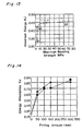
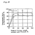
- Fig. 15 is a graph showing the relationship between the improvement ratio of energy absorbancy and the range of filling length of the filler material S (ratio of filling length to load fulcrum-to-fulcrum distance) in the case where the reinforcement Rf only was provided in the frame cross section, in the dynamic three-point bending test.
- white circles (o) denote a case in which wood was filled
- white triangles ( ⁇ ) denote a case in which epoxy resin A was filled.
- the absorbed energy increases with increasing range of filling length of the filler material S, but is saturated at about 15%.
- the range of filling of the filler material S is preferably 15% or more relative to the load fulcrum-to-fulcrum distance.
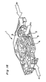
- Fig. 16 is a perspective view showing the body structure of an automobile, where when there arises a collision on the car body 1 from the front or rear side or from one side (see arrows Af, Ar, As in Fig. 16), then a collision load is inputted to the frame in various parts of the car body depending on the direction of the collision.
- a large impact load acts particularly on a so-called center pillar 2 extending vertically in body side portions. Therefore, it is important, in terms of occupant protection, to prevent the center pillar 2 from entering into the interior side due to a break of root portion or belt line portion of the center pillar 2. Accordingly, it is required for the center pillar 2 to enhance the absorbancy of collision energy by filling a filler material in these portions.
- a hinge pillar 4 extending vertically in the front side of the car-body side portion, of which its root portion is more likely to break, is preferably reinforced with a filler material.
- side sills 5 extending back and forth in both side portions of the car-interior floor, roof side rails 6 extending back and forth in both side portions of the car-interior roof and the like also are preferably reinforced by filling a filler material particularly at connecting portions with other frame members as well as their vicinities.
- the present inventor has found that the maximum bending moment bearable for the frame as well as the energy absorbancy can be enhanced to a large extent by interposing an adhesive layer between at least part of the panel member, which constitutes the frame, and a filler material in the process of filling the filler material into a cross section of the frame.
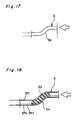
- Fig. 19 is an explanatory view schematically illustrating test equipment for conducting a static cantilever bending test of the frame.
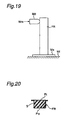
- a filler material S is filled into the cross section of the frame FR having a cross-sectional shape and a specified length as shown in Fig. 20
- one end of the frame FR is fixed to a support plate Me and this support plate Me is fixed to an equipment base Mf.
- a static load Wm applied to a vicinity of the other end of the frame FR via a presser Md by a universal tester, a relationship of displacement and bending angle to load is measured. In this way, maximum bending moment and static energy absorption amount were determined.
- Fig. 21 is a graph showing the relationship between bending angle and bending moment of frames with various types of filler materials filled.
- individual curves labeled “a” to “e” show characteristics of the frames to which the following filler materials were applied, respectively:
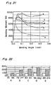
- Fig. 22 is a bar graph showing maximum bending moment (Nm) and energy absorption amount (J) of frames with various types of filler materials similar to those of Fig.. 21 filled, in the cantilever bending test.
- individual fields labeled "A" to "E” show characteristics of the frames to which the following filler material were applied, respectively.
- left-hand numerical values (white bars) represent maximum bending moment (Nm)
- right-hand numerical values represent energy absorption amount (J) of the frames:
- the frame of epoxy resin B + adhesive shows the greatest energy absorption amount, having a definite difference in comparison with the energy absorption amount in the case of field "C” using the same filler material (epoxy resin B).
- the energy absorption characteristic of the frame is greatly improved by fixing the filler material to the panel member of the frame with an adhesive.
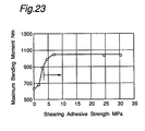
- Fig. 23 is a graph showing the relationship between the shearing adhesive strength of an adhesive layer and the maximum bending moment.
- the shearing adhesive strength of the adhesive layer As can be well seen from the graph of this Fig. 23, whereas the maximum bending moment bearable for the frame increases with increasing shearing adhesive strength of the adhesive layer, the degree of increase (gradient of the curve in the graph) in the maximum bending moment becomes gentler than before when the shearing adhesive strength becomes 3 MPa or more. In other words, if the shearing adhesive strength of the adhesive layer is 3 MPa or more, the maximum bending moment bearable for the frame can be increased quite effectively, so that a sufficient bending moment value can be achieved and a high energy absorbability can be obtained. Therefore, the shearing adhesive strength of the adhesive layer appropriately needs to be 3 MPa or more.
- the shearing adhesive strength of the adhesive layer is further preferably 7 MPa or more.
- the filler material when the filler material itself has an adhesive property, the filler material may also be bonded and fixed to the panel member of the frame, as it is, by taking advantage of the adhesive property without separately using an adhesive.
- the shearing adhesive strength is preferably 3 MPa or more, and more preferably 7 MPa or more.
- Fig. 24 is a process explanatory view outlining the manufacturing process of a vehicle body as shown in Fig. 16 and showing the filling operation in the case where, for example, a foamable filler material made of epoxy resin B is applied to a vehicle-body frame.
- steel plate members formed by pressing at step #1 are sub-assembled at assembly steps #2 and #3, where a filler material (e.g., epoxy resin B: with foaming temperature around 150 - 170°C) is filled by necessary portions at these assembly steps (see arrows).
- a filler material e.g., epoxy resin B: with foaming temperature around 150 - 170°C
- this filler material is foamed and hardened at the drying temperature.
- the filler material may also be foamed and hardened at this drying process.
- Fig. 25 is a process explanatory view showing in detail the application of a foamable filler material such as epoxy resin into a vehicle-body frame, by taking the center pillar as an example.
- Figs. 26 and 27 are explanatory views in longitudinal cross section showing vicinities of the belt line of the center pillar.
- Figs. 28A to 28E are process explanatory views showing detailed processes in setting a filler material into a cross section of this center pillar.
- an unfoamed filler material Sb is set to the inside of this reinforcement Rf (see Fig. 28D), and further the panel member Pi is assembled, by which the frame FR is made up (step #12; see Fig. 28E).
- the epoxy resin which is clay like in the unfoamed, can easily be set onto the outer panel Po or reinforcement Rf.
- an unfoamed filler material So (Sa + Sb) is filled in the frame cross section. Then, by foaming and hardening this filler material So, the frame FR in which the foamed and hardened filler material S is filled at a specified portion is formed as shown in Fig. 27.
- Example 1 is a frame in which a reinforcing member is disposed on a counter collision load input side of the filler material.
- Figs. 29 and 30 show a frame structure of, for example, a so-called center pillar as a car-body frame of an automobile.
- a frame FR1 in addition to a reinforcement Rf made of a steel plate disposed in parallel with an outer panel Po on the input side of a load W, a plurality of reinforcing members K1 formed into, for example, linear shape (wire shape) on the counter load input side in a frame cross section.
- These plurality of wire reinforcing members K1 are, more preferably , made of stainless steel and extending in parallel with an inner panel Pi (i.e., vertical to the direction of load input).
- the reinforcement Rf and the wire-like reinforcing members K1 are set, and besides, for example, epoxy resin is filled as a filler material S1 in the frame cross section.
- the wire-like reinforcing members K1 are set to this sheet-like filler material S1 so as to extend longitudinally of the frame.
- additional sheet-like filler materials S1 are stacked, and the setting of the reinforcing members K1 is done repeatedly.
- the filler material S1 e.g., epoxy resin
- the filler material S1 is foamed, by which a frame structure as shown in Figs. 29 and 30 can be obtained.
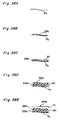
- Fig. 31 shows a frame FR2 according to a modification example of Example 1.
- a net-like sheet K2 made of stainless is used as the reinforcing member disposed on the counter collision load input side.
- a porous sheet material may be used, or wire-like reinforcing members may be crossed so as to be provided in a cross-net shape.
- reinforcing members K1, K2 are disposed on the counter collision load input side of the filler materials S1, S2 are provided as shown above, by which the bending strength on the counter collision load input side of the filler materials S1, S2 can be enhanced.
- the filler materials S1, S2 can be prevented from cracking upon the action of the collision load W, so that energy absorbability of the frames FR1, FR2 can be further enhanced.
- This Example 2 shows a frame structure in which the reinforcing member disposed in the frame cross section is further given a function of holding the filler material.
- a box-like reinforcing member K3 having a general U-shaped cross section is disposed on an outer side (i.e., load input side) in the frame cross section.
- This reinforcing member K3 comprises a body portion K3a extending generally parallel with the outer panel Po and the reinforcement Rf on the load input side, and a pair of upright wall portions K3b vertical to the body portion K3a (i.e., generally parallel with the direction of load input).
- the filler material S3 is held inside the box-like reinforcing member K3.
- This reinforcing member K3 is preparatorily joined to the panel member (i.e., reinforcement Rf) on the outer side by welding or adhesion in advance, and the filler material S3 is set to this joined body.
- the filler material S3 may be first set to the reinforcing member K3 and then joined to the reinforcement Rf.
- the reinforcing member K3 being disposed in the frame cross section, particularly outer side parts of the frame FR3 and the filler material S3 are reinforced. Besides, the filler material S3 is held to the reinforcing member K3.
- the frame FR3 can be simplified in structure and reduced in weight, while the two functions can be implemented.
- Fig. 33 shows a frame FR4 according to a modification example of Example 2.
- a reinforcing member K4 having a generally L-shaped cross section is disposed on the outer side (i.e., load input side) in the frame cross section.
- This reinforcing member K4 comprises a body portion K4a extending generally parallel with the outer panel Po on the load input side, and a upright wall portion K4b vertical (i.e., generally parallel with the direction of load input) to the body portion K4a. Then, the filler material S4 is held inside this L-shaped cross section.
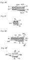
- Figs. 34 and 35 show frames FR5, FR6 according to other modification examples of Example 2.
- reinforcing members K5, K6 are disposed on the inner side of the frame cross section (i.e., counter load input side), respectively.
- a box-like reinforcing member K5 having a generally U-shaped cross section is disposed on the inner side (i.e., counter load input side) in the frame cross section.
- This reinforcing member K5 comprises a body portion K5a extending generally parallel with the inner panel Pi on the counter load input side, and a pair of upright wall portions K5b vertical to the body portion K5a (i.e., generally parallel with the direction of load input). Then, the filler material S5 is held inside this generally U-shaped, box-like reinforcing member K5.
- a reinforcing member K6 having a generally L-shaped cross section is disposed on the inner side (i.e., counter load input side) in the frame cross section.
- This reinforcing member K5 comprises a body portion K6a extending generally parallel with the inner panel Pi on the counter load input side, and a upright wall portions K6b vertical to the body portion K6a (i.e., generally parallel with the direction of load input). Then, the filler material S6 is held inside the generally L-shaped cross section.
- the reinforcing members K5, K6 reinforce the frames FR, FR6 and/or the filler materials S5, S6 on their inner side.
- the method for fixing the reinforcing members K5, K6 to the inner panel Pi is the same as in the case where the reinforcing member K3 is joined and fixed to the panel member (reinforcement Rf) on the outer side in the example of Fig. 32.
- This Example 3 shows a frame structure in which is provided a discharge hole for discharging electrodeposition liquid from the frame cross section and/or the portion of the filler material deposition in an electrodeposition process of a panel member constituting the frame cross section.
- a hole portion Hd drain hole extending longitudinally of the frame generally in contact with the inner panel Pi is provided, for example in a plurality, on the inner side (i.e., counter load input side) of the filler material S7 filled in the frame cross section.
- This drain hole Hd is intended to discharge the electrodeposition liquid from within the frame cross section and/or from the portions at which the filler material S7 is filled in the electrodeposition process in which the inner panel Pi and outer panel Po constituting the frame cross section as well as the reinforcement Rf are coated by electrodeposition.
- a pipe made of resin or steel is set on the inner side (counter load input side) of the filler material S7 prior to the assembly of the inner panel Pi, and after that, the filler material S7 is foamed and hardened, by which the drain hole Hd is formed generally in contact with the inner panel Pi.
- the electrodeposition liquid applied to within the frame FR7 in the electrodeposition process is allowed to flow via the drain hole Hd even when the filler material S7 is foamed and hardened. Therefore, the electrodeposition liquid is never blocked by, and before and after, the filler material S7, neither resides at the portions where the filler material S7 is filled. Further, since the drain hole Hd is formed with a pipe member extending along the longitudinal direction of the frame on the counter load input side, the filler material S7 is reinforced on the counter load input side, thus improved in bending strength.
- porous resin as an example may be provided on the inner side.
- the electrodeposition liquid can be discharged without obstacles through the drain hole Hd from within the frame cross section or from the portions at which the filler material S7 is filled.
- the filler material S7 can be reinforced on the counter load input side and thereby enhanced in bending strength by forming the drain hole Hd with a pipe member extending along the longitudinal direction of the frame. As a result, even if the filling length of the filler material S7 is set longer than a certain level, the filler material S7 can be prevented from cracking upon the action of a collision load, so that energy absorbability of the frame FR7 can be further enhanced.
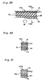
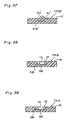
- This Example 4 shows a frame structure in which an adhesive layer is provided between at least part of the panel member constituting the frame cross section and a filler material layer.
- an adhesive layer is first applied onto the inner surface side of an outer panel Po, and besides an unfoamed filler material S8a (e.g., epoxy resin) is set (Fig. 38B). Then, a reinforcement Rf is assembled to the inside of the filler material S8a (Fig. 38C), and subsequently an adhesive layer is applied onto the inner and outer surfaces of the reinforcement Rf, and after these steps, an unfoamed filler material S8b (e.g., epoxy resin) is set.
- the reinforcement Rf may be assembled.
- the adhesive is applied onto the inner surface side of the inner panel Pi, and after that, the inner panel Pi is assembled, by which the frame FR8 is formed up.
- the adhesive instead of applying the adhesive onto the inner panel Pi side, the adhesive may be applied to the filler material S8b side. Taking into consideration that the electrodeposition liquid is applied to the inner panel Pi, the adhesive is preferably applied to the filler material S8b side.
- a frame FR8 in which the foamed and hardened filler material is filled at specified portions is formed up.
- the filler material is firmly bonded and fixed to the individual panel members.
- thermosetting adhesive whose shearing adhesive strength after heated to 165°C and cooled and hardened for 20 minutes was about 7 MPa was used in this embodiment.
- the filler material is filled in a portion of the frame FR upon which a bending moment acts, since the filler material is bonded and fixed to the panel member with an adhesive, the maximum bending moment bearable for the frame FR8 can be enhanced and therefore the energy absorbability can be improved, with a simple constitution.
- the adhesive layer is provided between the collision load input side of the filler material and at least part of the panel member (inner panel Pi), the compressive strength of the filler material on the collision load input side can be enhanced and therefore the energy absorbability can be further improved by effectively suppressing any crush of cross section of the frame FR8.
- This Example 5 shows another example of the frame structure in which an adhesive layer is provided between at least part of the panel member constituting the frame cross section and a filler material layer.
- an outer panel Po and a reinforcement Rf are first bonded and fixed at a specified point f9 (Fig. 39B).
- a so-called center pillar the belt line and its vicinities to which the cllision load is inputted are preferably bonded.
- an adhesive is applied to the inner surface side of the reinforcement Rf (Fig. 39C), and after that, a filler material S9 is set (Fig. 39D). Then, the adhesive is applied onto the inner surface of the inner panel Pi, and after that, the inner panel Pi is assembled, by which the frame FR9 is formed up (Fig. 39E). In this case, instead of applying the adhesive onto the inner panel Pi side, the adhesive may be applied to the filler material S9 side.
- the frame rigidity at this portion as well as the compressive strength of the filler material S9 on the collision load input side can be enhanced and therefore the energy absorbability can be further improved by effectively suppressing any crush of cross section of the frame FR9.
- This Example 6 shows a frame structure in which electrodeposition liquid is allowed to flow without obstacles on the inner surface of the panel member in the process of electrodeposition to the panel member constituting the frame cross section.
- a rod-like member B1 extending in the longitudinal direction of the frame is provided, for example in a plurality, in adjacency to the inner panel Pi on the inner side (i.e., counter load input side) of the frame cross section.
- This rod-like member B1 is made of, for example, resin or steel, and set so as to protrude toward the inner panel Pi side into contact with the inner panel Pi on the counter load input side of the unfoamed filler material S10.
- the filler material S10 is set separate from the inner panel Pi with a specified gap as well as separate from the reinforcement Rf also with a specified gap, via the rod-like member B1, i.e., set in a floating state within the frame cross section, thus allowing the electrodeposition liquid to flow without obstacles on the inner surface of the panel member in the process of electrodeposition to the panel member. Then, after that, by foaming and hardening the filler material S10, interior of the frame cross section is generally entirely filled with the filler material S10.
- the filler material S10 is reinforced on the counter load input side by the rod-like member B1 extending longitudinally of the frame, the bending strength of the filler material S10 is improved and therefore the energy absorbability is enhanced.
- Example 7 shows a frame structure in which electrodeposition liquid is allowed to flow without obstacles on the inner surface of the panel member in the process of electrodeposition to the panel member constituting the frame cross section.
- a pair of rectangular plate members B2 (support plates) vertical to the panel member (i.e., in the direction of load input) are provided in the frame cross section, and an unfoamed filler material S11 is set between these support plates B2.
- a rod-like member B3 is provided, for example in a plurality, with both ends supported by these pair of plate members B2, and the unfoamed filler material S11 is set so as to be wound around these rod-like members B3.
- each plate member B2 At four corners of each plate member B2 are provided leg portions B2a protruding toward the inner side or outer side. By each leg portion B2a contacting the inner panel Pi or the reinforcement Rf, a specified or more gap is maintained with these panel members Pi, Rf.
- the filler material S11 is set in a floating state within the frame cross section, thus allowing the electrodeposition liquid to flow without obstacles on the inner surface of the panel members in the process of electrodeposition to the panel members. Then, after that, by foaming and hardening the filler material S11, interior of the frame cross section is generally entirely filled with the filler material S11.
- the filler material S11 is reinforced on the counter load input side by the rod-like member B3 and therefore improved in bending strength, so that the energy absorbability is enhanced.
- This Example 8 shows a frame structure in which the filling state of a filler material in the frame cross section can be verified from outside the frame.
- a hole portion Hi for inspection is provided in an inner panel Pi.
- This hole portion Hi for inspection has a diameter of, for example, about 5 mm, and is provided at a point corresponding to the filling portion of a filler material S12.
- the foamable filler material S12 foamed and hardened if the degree of filling is sufficient, it can be checked because the filler material is swollen from this hole portion Hi.
- a foamable filler material such as epoxy resin
- the hole has a diameter of about 5 to 7 mm or less, the filler material never leaks out of the hole portion. It is also possible that air ventilation is done through this hole portion Hi during the foaming process of the filler material S12.
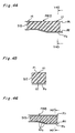
- This Example 9 shows a frame structure in which the panel member has a protrusion formed so as to hold the filler material.
- a multiplicity of protrusions Rfa are formed on the inner surface side of the reinforcement Rf. These protrusions Rfa are formed so as to extend, more preferably, not vertically to the inner surface of the reinforcement Rf but obliquely upward with the frame FR13 attached to the car body. Then, the filler material S13 is held to the reinforcement Rf in a state that the load input side of the filler material S13 is engaged with the protrusions Rfa. Accordingly, the filler material S13 never falls off downward (rightward in the figure) within the frame FR13.
- This structure is capable of holding the filler material S13 to within the frame cross section without requiring the provision of any separate member (i.e., without incurring any complication of structure), thus being particularly effective for not only cases where such foamable filler material as epoxy resin is held in an unfoamed state, but also cases where a woody filler material is held.
- This Example 10 shows a frame structure in which with a foamable material set between filler material and panel member, the filler material is held and fixed to the panel member by this foamable material.
- a foamable filler material S14b is set in an unfoamed state between a, for example, woody filler material S14a and an inner panel Pi as well as between the filler material S14a and a reinforcement Rf, and then the unfoamed filler material S14b is foamed and hardened, by which the filler material S14a is held and fixed between the inner panel Pi and the reinforcement Rf.
- the filler material S14a can be held within the frame cross section without requiring the provision of any separate member (i.e., without incurring any complication of structure).
- This Example 11 shows a frame structure in which a filler material can be filled stably at a target site by lowering the apparent foaming rate of the foamable filler material.
- a foamable (e.g., epoxy resin) filler material S15a is set in the frame FR15 in a preparatorily foamed and hardened state, and then a foamable (e.g., epoxy resin) filler material S15b is set between the foamed and hardened filler material S15a and an inner panel Pi and between the filler material S15a and a reinforcement Rf. Subsequently, this unfoamed filler material S15b is foamed and hardened at the time of, for example, drying in the electrodeposition process, by which the filler material S15a is held and fixed between the inner panel Pi and the reinforcement Rf.
- a foamable (e.g., epoxy resin) filler material S15a is set in the frame FR15 in a preparatorily foamed and hardened state, and then a foamable (e.g., epoxy resin) filler material S15b is set between the foamed and hardened filler material S15a and an inner panel Pi and between the filler material
- the foaming rate of the filler material is higher than a certain level, there are some cases where the filler material cannot be filled enough at an originally targeted site within the frame depending on the configuration of the frame. However, by lowering the apparent foaming rate as in this example, it becomes possible to achieve stable filling to the target sites.
- the filler material is set into the frame cross section in the low-temperature foaming state and then finally foamed at high temperature (for example, in the electrodeposition drying process), by which a 100% foaming rate is obtained.
- the apparent foaming rate in the final foaming process lowers by an extent of the previous foaming at low temperature.
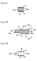
- This Example 12 shows a frame structure in which a filler material is held by a specified support member within the frame cross section so that electrodeposition liquid is allowed to flow without obstacles on the inner surface of the panel member in the electrodeposition process to the panel member constituting the frame cross section.
- a box-like support member B5 comprising a pair of upright wall portions B6 vertical to the panel member (i.e., in the direction of load input) and a plate-shaped body portion B7 parallel with the inner panel Pi is provided within the frame cross section, and then an unfoamed foamable filler material S16 (e.g., epoxy resin) is set inside the support member B5.
- an unfoamed foamable filler material S16 e.g., epoxy resin
- each upright wall portion B6 At four corners of each upright wall portions B6 are provided leg portions B6a protruding toward the inner side or outer side. By each leg portion B6a on the load input side contacting the reinforcement Rf, a specified or more gap is maintained between the unfoamed filler material S16 and the reinforcement Rf and between the filler material S16 and the inner panel Pi.
- the electrodeposition liquid is allowed to flow without obstacles on the inner surface of the panel member in the electrodeposition process to the panel members Pi, Po and Rf. Then, after that, the filler material S16 is foamed and hardened.
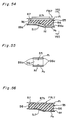
- Figs. 54 to 56 show a modification example of Example 12.
- a porous portion B7h with a multiplicity of holes having a specified or more diameter is provided in a frame FR17 according to this modification example. Then, when an unfoamed filler material S17 is foamed and hardened, the filler material S17 is filled through the hole portions of the porous portion B7h to the inner side, by which the filler material S17 is filled without obstacles to not only the outer side but also the inner side of the frame FR17.
- the filler material S17 is reinforced on the counter load input side by the body portion B7 of the support member B5, the filler material S17 is improved in bending strength so that the energy absorbability of the frame FR17 is enhanced.
- This Example 13 shows a frame structure in which when an opening portion is formed by burying, for example, nuts or the like in the panel member of the frame, this opening portion is prevented from being closed by the filler material.
- a sheet member B8 made of paper or vinyl for use of preventing the entrance of filler materials is disposed on the counter inner panel Pi side of the nut Nt. Accordingly, when the filler material S18 is foamed and hardened, this foamed filler material S18 never enters into the nut hole Hn.
- Fig. 59 shows a modification example of Example 13.
- a cap member B9 made of resin for use of preventing the entrance of filler materials is disposed on the counter inner panel Pi side of the nut Nt, and the entrance of the filler material S19 is prevented by the cap member B9.
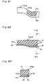
- This Example 14 shows a frame structure in which with a woody filler material impregnated with a foamable material, the filler material is fixed to the frame by making this foamable material foamed.
- a woody filler material S20 such as pine or Japanese cedar formed in compliance with the configuration of the filling site of the frame is sliced into a thickness of about 1 mm (Fig. 60A), and a plurality of woody materials S20 sliced in this way are stacked by adhesion, for example, with an epoxy resin or phenol resin adhesive.
- the filler material S20 is dipped in a resin bath B10 where, for example, epoxy resin or phenol resin including foamable components (Fig. 60B) is stored.
- a pressure is applied, as required, to accelerate the impregnation of resin into the woody filler material S20.
- the woody filler material S20 impregnated with foamable components as shown above is set into the frame FR20, and then dried, for example, after electrodeposition coating. By this drying step, the foamable components impregnated in the woody filler material S20 are foamed, so that the filler material S20 is fixed in close contact to the inner panel Pi and the reinforcement Rf (Figs. 60C and 60D).
- the filler material S20 can be fixed in close contact to the panel members (inner panel Pi and reinforcement Rf) of the frame FR20 by the foamable components impregnated in the woody filler material S20 without any particular use of adhesive.
- This Example 15 shows a frame structure in which reinforcement is implemented by filling a filler material to a portion of the frame upon which the bending moment intensively acts.
- a reinforcing member B21 that forms a closed cross section in association with an inner panel Pi21 is fixed at a bent portion of the frame FR21, and, for example, a foamable filler material S21 (e.g., epoxy resin) is filled as a porous filler material in the closed cross section.
- a foamable filler material S21 e.g., epoxy resin
- This reinforcing member B21 has functions of reinforcing the frame FR21 as well as holding the filler material S21.
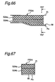
- This Example 16 provides a structure in which the closeness of adhesive is enhanced by making the holes of the porosity independent of one another.
- a porous filler material S22 is filled in a closed cross section formed by an inner panel Pi and a reinforcement Rf, where a plurality of independent hole portions Sh are formed in a surface opposite to the reinforcement Rf in this filler material S22. Then, the filler material S22 is bonded and fixed to the inner surface of the reinforcement Rf at an adhesive layer Ad.
- the hole portions Sh of the porous material (filler material S22) independent of one another, occurrence of cracks from the hole portions upon load inputs can be suppressed, while the adhesion of the adhesive can be enhanced by increasing the adhesion area of the adhesive Ad, so that a stabler adhesive force can be obtained.
- an improvement effect of the bending moment bearable for the frame FR22 can be obtained stably, and the energy absorbability can be improved.
- This Example 17 shows a frame structure in which different filler materials having a mean compressive strength characteristic or maximum bending strength characteristic disclosed in the present invention are disposed as a multilayer structure.
- a plurality of sheets of S23a (first filler material layer) given by a filler material (first filler material) having a maximum bending strength of 10 MPa or more as the maximum bending strength characteristic disclosed in the present invention and formed into a plate shape of a specified thickness
- a plurality of sheets of S23b (second filler material layer) given by a filler material (second filler material) having a mean compressive strength of 4 MPa or more as the mean compressive strength characteristic disclosed in the present invention and formed into a plate shape of a specified thickness are prepared.
- these plate-shaped filler material layers S23a, s23b are filled, for example, so as to be alternately stacked, in a closed cross section formed by an inner panel Pi and a reinforcement Rf of the frame FR23.
- the mean compressive strength of the first filler material is less than 4 MPa
- the maximum bending strength of the second filler material is less than 10 MPa.
- the first filler material layer S23a having a maximum bending strength of 10 MPa or more and the second filler material layer S23b having a mean compressive strength of 4 MPa or more it becomes possible to obtain, by using the filler materials S23a, S23b which have only one of the above characteristics,. respectively, a filler material as a whole having both characteristics (i.e., a maximum bending strength of 10 MPa or more and a mean compressive strength of 4 MPa or more).
- This Example 18 shows a frame structure in which different filler materials having a mean compressive strength characteristic or maximum bending strength characteristic disclosed in the present invention are disposed as a two-layer structure on the load input side and counter load input side of the frame.
- filler materials different in strength characteristics are disposed on load input side and counter load input side of the frame FR24, respectively. That is, a filler material S24a superior in maximum bending strength characteristic is disposed on the counter load input side while a filler material S24b superior in mean compressive strength characteristic is disposed on the load input side.
- the filler material S24a on the counter load input side has a maximum bending strength of 10 MPa or more as the maximum bending strength characteristic disclosed in the present invention
- the filler material S24b on the load input side has a mean compressive strength of 4 MPa or more as the mean compressive strength characteristic disclosed in the present invention.
- first filler material layer S24a having a maximum bending strength of 10 MPa or more on the counter load input side of the frame FR24 and disposing the second filler material layer S24b having a mean compressive strength of 4 MPa or more on the load input side, it becomes possible to impart the most effective strength characteristics to the load input side and the counter load input side of the frame FR24, respectively, easily and securely.
- the present invention can be effectively applied to other vehicle-body frames such as other pillar members extending vertically in a vehicle-body side portion of an automobile (e.g., front pillar, hinge pillar portion, rear pillar, etc.), frame members extending back and forth in car-body both sides of an automobile (e.g.
- connecting members for connecting right and left frame members e.g., so-called cross-members, etc.
- reinforcing members of a door body e.g., so-called impact bar, etc.
- reinforcing members of bumpers e.g., so-called bumper reinforcement, etc.
- the filler material is set to a mean compressive strength of not less than 4 MPa or a maximum bending strength of not less than 10 MPa. Therefore, by the mean compressive strength being not less than 4 MPa, the possibility that the frame is largely deformed locally at the load input point and its vicinities to yield crushes of the cross section is suppressed, and a high energy absorbability can be obtained by effectively diffusing the input load to the frame support portions.
- the maximum bending strength being not less than 10 MPa, even if the frame is largely deformed locally at the load input point and its vicinities, occurrence of cracks in the filler material is suppressed and the frame is prevented from breaking in terms of brittleness, and moreover a high energy absorbability can be obtained by effectively diffusing the input load to the frame support portions.
- the compressive load that directly acts mainly on the load input side can be effectively borne, and moreover the bending load that directly acts mainly on the counter load input side can be effectively borne. That is, the most effective characteristics are imparted to the load input side and the counter load input side of the frame, respectively, so that an efficient reinforcement can be implemented.
- a reinforcing member is disposed on the counter collision load input side of the filler material, the bending strength on the counter collision load input side of the filler material can be enhanced.
- the filling length of the filler material is set longer than a certain level, occurrence of cracks in the filler material upon action of a collision load on the frame can be suppressed and the energy absorbability of the frame can be further enhanced.
- the filler material is set to a mean compressive strength of not less than 5 MPa and/or a maximum bending strength of not less than 60 MPa, the same effects as in the first aspect can be obtained more stably.
- a filler material layer having the mean compressive strength and a filler material layer having the maximum bending strength by multilayering and stacking a filler material layer having the mean compressive strength and a filler material layer having the maximum bending strength, a filler material as a whole having both characteristics can be obtained. Also, by providing a filler material layer having the mean compressive strength on the load input side of the frame and disposing a filler material layer having the maximum bending strength on the counter load input side, the most effective characteristics can be imparted to the load input side and the counter load input side of the frame, respectively, easily and securely.
- the frame becomes lightweight and a high energy absorbability can be obtained.
- the filling work into the frame cross section can be easily and securely achieved by taking advantage of the foamability of the resin.
- the filler material is filled over a range of 15% or more of a length between load fulcrums of the frame, a high energy absorbability can be obtained by effectively diffusing the input load from the input point side into the frame.
- both the function of reinforcing the frame and/or the filler material and the function of holding the filler material can be implemented by one member, the two functions can be realized while the frame is simplified in structure and reduced in weight.
- the electrodeposition liquid can be discharged without obstacles through this drain hole from within the frame cross section and/or from the portions at which the filler material is filled.
- the discharge hole is provided on the counter load input side of the filler material, the counter load input side of the filler material can be reinforced and the bending strength can be enhanced, by forming the hole with a member extending longitudinally of the frame.
- the rigidity of portions of the frame where the filler material is filled can be enhanced with a simple constitution by only applying an adhesive.
- the filler material is filled in a portion of the frame upon which the bending moment acts, since the filler material is bonded and fixed to the panel member with an adhesive, the maximum bending moment bearable for the frame can be enhanced and therefore the energy absorbability can be improved, with a simple constitution.
- the adhesive layer is provided between the collision load input side of the filler material and at least part of the panel member, the rigidity of the filler material on the collision load input side is enhanced while the input load can be securely diffused, so that crushes of the cross section of the frame can be suppressed and that the energy absorbability can be further improved.
- the adhesive layer has a shearing adhesive strength of not less than 3 MPa, the maximum bending moment bearable for the frame can be increased quite effectively, so that a high energy absorbability can be obtained.
- the shearing adhesive strength of the filler material itself is not less than 3 MPa, the maximum bending moment bearable for the frame can be increased quite effectively, so that a high energy absorbability can be obtained.
- the holes of the porosity are formed independently so that the closeness of the adhesive is enhanced, a more effective adhesion can be obtained, the maximum bending moment bearable for the frame can be enhanced stably, and the energy absorbability can be improved.
- the energy absorbability of a vehicle-body frame can be improved when the frame structure of this invention is applied to at least any one of pillar members extending vertically in a car-body side portion of an automobile (e.g., center pillar, front pillar, hinge pillar portion, rear pillar, etc.), frame members extending back and forth in car-body both sides of an automobile (e.g., side sill, rear side frame and front frame, etc.), connecting members for connecting right and left frame members (e.g., so-called cross-members; etc.), reinforcing members of a door body (e.g., so-called impact bar, etc.) and reinforcing members of bumpers (e.g., so-called bumper reinforcement, etc.).
- pillar members extending vertically in a car-body side portion of an automobile
- frame members extending back and forth in car-body both sides of an automobile (e.g., side sill, rear side frame and front frame, etc.)
- connecting members for connecting right and left frame members
Landscapes
- Engineering & Computer Science (AREA)
- Mechanical Engineering (AREA)
- Chemical & Material Sciences (AREA)
- Combustion & Propulsion (AREA)
- Transportation (AREA)
- Architecture (AREA)
- Structural Engineering (AREA)
- Physics & Mathematics (AREA)
- Manufacturing & Machinery (AREA)
- Materials Engineering (AREA)
- Optics & Photonics (AREA)
- Body Structure For Vehicles (AREA)
Claims (14)
- Rahmenstruktur für Fahrzeugkarosserien bzw. -Rahmenstruktur für Fahrzeugkarosserien, welche(r) eine Kollisionsbelastungs-Eintrittsseite und eine Gegen-Kollisionsbelastungs-Eintrittsseite aufweist, in welchem (welcher) ein geschäumtes Füllmaterial (S, S1, S2, ...) in wenigstens einen Bereich bzw. Abschnitt eines Querschnitts des Rahmens (FR, FR1, ...) gefüllt ist, dadurch gekennzeichnet, daß
das geschäumte Füllmaterial eine mittlere Druckfestigkeit von nicht weniger 4 MPa, definiert für die Kollisionsbelastungs-Eintrittsseite, und eine maximale Biegefestigkeit von nicht weniger 10 MPa, definiert für die Gegen-Kollisionsbelastungs-Eintrittsseite, aufweist und daß ein Verstärkungsglied (K1, K2) eingebettet in dem geschäumten Füllmaterial an der Gegen-Kollisionsbelastungs-Eintrittsseite angeordnet ist. - Rahmenstruktur für Fahrzeugkarosserien nach Anspruch 1, worin das geschäumte Füllmaterial (S, S1, S2, ...) eine mittlere Druckfestigkeit von nicht weniger als 5 MPa und/oder eine maximale Biegefestigkeit von nicht weniger als 60 MPa aufweist.
- Rahmenstruktur für Fahrzeugkarosserien nach Anspruch 1 oder 2, worin unterschiedliche, geschäumte Füllmaterialien (S23a, S23b), welche die Merkmale aufweisen, in einer Form einer Mehrschicht-Struktur angeordnet sind.
- Rahmenstruktur für Fahrzeugkarosserien nach einem der Ansprüche 1 bis 3, worin das geschäumte Füllmaterial (S, S1, S2, ...) eine Dichte von nicht weniger als 1,0 g/cm3 aufweist.
- Rahmenstruktur für Fahrzeugkarosserien nach einem der Ansprüche 1 bis 4, worin das geschäumte Füllmaterial Epoxyharz ist.
- Rahmenstruktur für Fahrzeugkarosserien nach einem der Ansprüche 1 bis 5, worin das geschäumte Füllmaterial (S) über einen Bereich von 15 % oder mehr als eine Länge zwischen Lastgelenk- bzw. -drehpunkten des Rahmens (FR) gefüllt ist.
- Rahmenstruktur für Fahrzeugkarosserien nach einem der Ansprüche 1 bis 6, worin ein Verstärkungsglied (K3, K4, K5, K6) zum Verstärken des Rahmens (FR) und/oder des Füllmaterials (S, S1, S2, ...) in wenigstens einem Bereich des Rahmenquerschnitts angeordnet ist und das Verstärkungsglied bzw. die Verstärkungsglieder (K3, K4, K5, K6) eine Haltefunktion zum Halten des Füllmaterials (S, S0, S1, ...) aufweist bzw. aufweisen.
- Rahmenstruktur für Fahrzeugkarosserien nach einem der Ansprüche 1 bis 7, worin an der Gegen-Kollisionsbelastungs-Eintrittsseite des Füllmaterials (S1, S2) ein Ausbringloch (Hd) zum Ausbringen einer Galvanik-Flüssigkeit aus dem Rahmenquerschnitt und/oder eines Bereichs der Füllmaterialabscheidung in einem Galvanik- bzw. Elektroabscheidungsprozeß eines Platten- bzw. Tafelglieds vorgesehen ist, welches den Rahmenquerschnitt darstellt.
- Rahmenstruktur für Fahrzeugkarosserien nach einem der Ansprüche 1 bis 8, worin eine Haft- bzw. Klebeschicht (Ad) zwischen wenigstens einem Abschnitt des Plattenglieds (Pi, Po), welches den Rahmenquerschnitt darstellt bzw. ausbildet, und der Füllmaterialschicht vorgesehen ist.
- Rahmenstruktur für Fahrzeugkarosserien nach Anspruch 9, worin die Haftschicht (Ad) zwischen der Kollisionsbelastungs-Eintrittsseite des Füllmaterials und wenigstens einem Teil des Plattenglieds (Pi, Po) vorgesehen ist.
- Rahmenstruktur für Fahrzeugkarosserien nach Anspruch 9 oder 10, worin die Haftschicht (Ad) eine Scherhaftfestigkeit von nicht weniger als 3 MPa aufweist.
- Rahmenstruktur für Fahrzeugkarosserien nach Anspruch 11, worin das Füllmaterial selbst eine Scherhaftfestigkeit von nicht weniger als 3 MPa aufweist.
- Rahmenstruktur für Fahrzeugkarosserien nach einem der Ansprüche 9 bis 12, worin das geschäumte Füllmaterial (S22) unabhängig ausgebildete Löcher (Sh) aufweist, wodurch die Dichtheit bzw. Festigkeit bzw. Geschlossenheit des Haftmittels (Ad) vergrößert ist.
- Rahmenstruktur für Fahrzeugkarosserien nach einem der Ansprüche 1 bis 13, worin der Kraftfahrzeug-Karosserierahmen wenigstens auf eines von einem Säulenglied, welches sich nach oben und unten in Seitenabschnitten einer Fahrzeugkarosserie eines Kraftfahrzeugs erstreckt, einem Rahmenglied, welches sich nach vorwärts und rückwärts an beiden Seiten einer Fahrzeugkarosserie eines Kraftfahrzeugs erstreckt, einem Verbindungsglied zum Koppeln der Rahmenglieder auf der linken und rechten Seite, einem Verstärkungsglied eines Türkörpers bzw. einem Verstärkungsglied einer Stoßstange angewandt ist.
Applications Claiming Priority (3)
| Application Number | Priority Date | Filing Date | Title |
|---|---|---|---|
| JP08726098A JP3525731B2 (ja) | 1998-03-31 | 1998-03-31 | 車体のフレーム構造 |
| JP8726098 | 1998-03-31 | ||
| PCT/JP1999/001619 WO1999050127A1 (en) | 1998-03-31 | 1999-03-30 | Frame structure for vehicle body |
Publications (2)
| Publication Number | Publication Date |
|---|---|
| EP0983183A1 EP0983183A1 (de) | 2000-03-08 |
| EP0983183B1 true EP0983183B1 (de) | 2002-07-17 |
Family
ID=13909815
Family Applications (1)
| Application Number | Title | Priority Date | Filing Date |
|---|---|---|---|
| EP99910767A Expired - Lifetime EP0983183B1 (de) | 1998-03-31 | 1999-03-30 | Kraftfahrzeug-rahmenaufbau |
Country Status (9)
| Country | Link |
|---|---|
| US (1) | US6296299B1 (de) |
| EP (1) | EP0983183B1 (de) |
| JP (1) | JP3525731B2 (de) |
| KR (1) | KR20010013212A (de) |
| CN (1) | CN1100690C (de) |
| DE (1) | DE69902128T2 (de) |
| ES (1) | ES2181405T3 (de) |
| TW (1) | TW479033B (de) |
| WO (1) | WO1999050127A1 (de) |
Families Citing this family (24)
| Publication number | Priority date | Publication date | Assignee | Title |
|---|---|---|---|---|
| DE10006388A1 (de) * | 2000-02-12 | 2001-08-16 | Volkswagen Ag | Hilfsrahmen eines Kraftfahrzeugfahrwerks |
| DE10153712C1 (de) * | 2001-10-31 | 2003-05-28 | Imperia Ges Fuer Angewandte Fa | Leichtbauteil |
| US7509191B2 (en) * | 2003-09-12 | 2009-03-24 | Honda Motor Co., Ltd. | Frame deformation control apparatus |
| KR100844644B1 (ko) * | 2006-12-10 | 2008-07-07 | 현대자동차주식회사 | 차량의 외측 패널구조 |
| US7677036B2 (en) * | 2007-07-02 | 2010-03-16 | Hall David R | Hydraulic energy storage with an internal element |
| US7908851B2 (en) * | 2007-07-02 | 2011-03-22 | Hall David R | Hydraulic energy storage with reinforced layer |
| US7600376B2 (en) * | 2007-07-02 | 2009-10-13 | Hall David R | Energy storage |
| US7891453B2 (en) | 2007-07-02 | 2011-02-22 | Schlumberger Technology Corporation | Energy storage in an elastic vessel |
| US20090008918A1 (en) * | 2007-07-02 | 2009-01-08 | Hall David R | Expandable Vehicle Frame |
| KR20160085363A (ko) * | 2008-07-29 | 2016-07-15 | 다우 글로벌 테크놀로지스 엘엘씨 | 자동차 캐비티의 강성화 및 에너지 소산을 위한 강인화된 발포성 에폭시 수지 |
| DE102009030349B4 (de) * | 2009-06-25 | 2020-01-02 | GM Global Technology Operations LLC (n. d. Ges. d. Staates Delaware) | Seitenstruktur eines Fahrzeugs |
| JP5154672B2 (ja) * | 2011-05-24 | 2013-02-27 | Jfeスチール株式会社 | 自動車用骨格部品 |
| JP5853481B2 (ja) * | 2011-08-08 | 2016-02-09 | マツダ株式会社 | 車両用フレーム構造およびその製造方法 |
| US11097782B2 (en) | 2014-11-24 | 2021-08-24 | Tesseract Structural Innovations, Inc. | Sill beam uniform deceleration unit |
| JP7296692B2 (ja) * | 2016-03-03 | 2023-06-23 | 日本製鉄株式会社 | 車両用構造部材 |
| MX2018011672A (es) * | 2016-04-01 | 2019-02-18 | Nippon Steel & Sumitomo Metal Corp | "tuberia de metal y miembro estructural con tuberia de metal". |
| RU2696136C1 (ru) * | 2016-06-07 | 2019-07-31 | Ниппон Стил Энд Сумитомо Метал Корпорейшн | Металлическая труба и конструктивный элемент, использующий металлическую трубу, для транспортного средства |
| EP3677490B1 (de) * | 2017-09-01 | 2023-07-26 | Nippon Steel Corporation | Hohlkörper |
| BR112020003637A2 (pt) * | 2017-09-01 | 2020-09-01 | Nippon Steel Corporation | membro oco |
| JP6798457B2 (ja) * | 2017-09-15 | 2020-12-09 | トヨタ自動車株式会社 | バンパリインフォースメント |
| WO2019181434A1 (ja) | 2018-03-22 | 2019-09-26 | 東レ株式会社 | 複合構造体 |
| JP2021522097A (ja) * | 2018-04-16 | 2021-08-30 | テッサラクト ストラクチュラル イノベーションズ,インコーポレイテッド | 均一減速ユニット |
| DE102018127011A1 (de) * | 2018-10-30 | 2020-04-30 | Bayerische Motoren Werke Aktiengesellschaft | Fahrzeugstrukturbauteil, Baukastensystem und Verfahren zur Herstellung von Fahrzeugstrukturbauteilen |
| KR102869570B1 (ko) * | 2020-12-01 | 2025-10-14 | 닛폰세이테츠 가부시키가이샤 | 자동차의 차체 하부 구조 |
Family Cites Families (28)
| Publication number | Priority date | Publication date | Assignee | Title |
|---|---|---|---|---|
| US3574379A (en) * | 1968-07-08 | 1971-04-13 | Alexander T Jordan | Resilient shock-absorbing bumper |
| US3829149A (en) * | 1973-02-09 | 1974-08-13 | L & L Prod Inc | Beam construction |
| US4190712A (en) * | 1974-06-21 | 1980-02-26 | Mccord Corporation | Low density energy management urethane foam |
| US4061384A (en) * | 1976-04-29 | 1977-12-06 | General Motors Corporation | Bumper having pivotal load spreader plate for deflecting energy absorbing medium |
| JPS57151347A (en) * | 1981-03-16 | 1982-09-18 | Nissan Motor | Reinforcing material for reinforcing board material |
| JPS58221745A (ja) * | 1982-06-19 | 1983-12-23 | Japan Styrene Paper Co Ltd | 自動車のバンパ−用芯材 |
| US4559252A (en) * | 1983-06-09 | 1985-12-17 | Toyota Jidosha Kabushiki Kaisha | Plate metal reinforcing combination |
| US4542165A (en) | 1983-09-08 | 1985-09-17 | Sanyo Chemical Industries, Ltd. | Polyurethane based on epoxy-containing polymer polyol and process for making the same |
| DE3345576A1 (de) * | 1983-12-16 | 1985-06-27 | Ford-Werke AG, 5000 Köln | Sandwich-bauteil, insbesondere haube, klappe oder dergleichen fuer eine kraftfahrzeugkarosserie |
| GB8511191D0 (en) * | 1985-05-02 | 1985-06-12 | Ford Motor Co | Vehicle bumper assembly with foamed core |
| JP2694650B2 (ja) * | 1988-07-08 | 1997-12-24 | スズキ株式会社 | 車両用バンパの構造 |
| JPH0788175B2 (ja) * | 1988-12-28 | 1995-09-27 | 日産自動車株式会社 | 車体構造部材への樹脂注入強化方法および注入樹脂のせき止め構造 |
| JPH07100456B2 (ja) | 1989-06-30 | 1995-11-01 | 日産自動車株式会社 | 発泡ウレタン充填車体構造 |
| US4978562A (en) * | 1990-02-05 | 1990-12-18 | Mpa Diversified Products, Inc. | Composite tubular door beam reinforced with a syntactic foam core localized at the mid-span of the tube |
| US5124186A (en) | 1990-02-05 | 1992-06-23 | Mpa Diversified Products Co. | Composite tubular door beam reinforced with a reacted core localized at the mid-span of the tube |
| US5005887A (en) * | 1990-04-09 | 1991-04-09 | Davidson Textron Inc. | Energy absorbing bumper fastener system |
| US5046778A (en) * | 1990-06-29 | 1991-09-10 | The Standard Products Company | Reduced weight vehicle door pillar |
| DE4133144A1 (de) * | 1990-10-04 | 1992-04-09 | Mannesmann Ag | Aufpralltraeger |
| JP2940720B2 (ja) * | 1991-05-13 | 1999-08-25 | 日本ゼオン株式会社 | 車両用制振剛性構造体 |
| US5139297A (en) * | 1991-09-12 | 1992-08-18 | Ford Motor Company | Internal stroking bumper beam |
| JPH0691325A (ja) * | 1992-04-09 | 1994-04-05 | Nippon Steel Corp | 自動車ドア補強材用鋼管 |
| DE9210180U1 (de) | 1992-07-30 | 1992-09-24 | Leichtmetallbau Mauderer GmbH, 88161 Lindenberg | Profilträger |
| JP3954119B2 (ja) * | 1995-01-21 | 2007-08-08 | イイダ産業株式会社 | 加熱発泡充填補強材及び同加熱発泡充填補強材を用いた閉断面構造部材補強構造 |
| US5580116A (en) * | 1995-04-05 | 1996-12-03 | Ford Motor Company | Trim component having energy absorbing feature |
| DE29514164U1 (de) * | 1995-09-04 | 1997-01-09 | Ebbinghaus, Alfred, 73431 Aalen | Ausgeschäumtes Formteil |
| US5720510A (en) * | 1996-03-28 | 1998-02-24 | Ford Global Technologies, Inc. | Energy absorbing vehicle pillar structure |
| US5799991A (en) * | 1996-10-23 | 1998-09-01 | Concept Analysis Corporation | Molded bumper system with reinforcement beam |
| US5806919A (en) * | 1996-11-04 | 1998-09-15 | General Motors Corporation | Low density-high density insert reinforced structural joints |
-
1998
- 1998-03-31 JP JP08726098A patent/JP3525731B2/ja not_active Expired - Fee Related
-
1999
- 1999-03-30 WO PCT/JP1999/001619 patent/WO1999050127A1/en not_active Ceased
- 1999-03-30 TW TW088104986A patent/TW479033B/zh not_active IP Right Cessation
- 1999-03-30 CN CN99800410A patent/CN1100690C/zh not_active Expired - Fee Related
- 1999-03-30 DE DE69902128T patent/DE69902128T2/de not_active Expired - Lifetime
- 1999-03-30 EP EP99910767A patent/EP0983183B1/de not_active Expired - Lifetime
- 1999-03-30 KR KR19997011200A patent/KR20010013212A/ko not_active Ceased
- 1999-03-30 US US09/423,313 patent/US6296299B1/en not_active Expired - Lifetime
- 1999-03-30 ES ES99910767T patent/ES2181405T3/es not_active Expired - Lifetime
Also Published As
| Publication number | Publication date |
|---|---|
| JPH11278301A (ja) | 1999-10-12 |
| CN1100690C (zh) | 2003-02-05 |
| TW479033B (en) | 2002-03-11 |
| WO1999050127A1 (en) | 1999-10-07 |
| EP0983183A1 (de) | 2000-03-08 |
| US6296299B1 (en) | 2001-10-02 |
| DE69902128D1 (de) | 2002-08-22 |
| JP3525731B2 (ja) | 2004-05-10 |
| ES2181405T3 (es) | 2003-02-16 |
| KR20010013212A (ko) | 2001-02-26 |
| DE69902128T2 (de) | 2003-03-27 |
| CN1262652A (zh) | 2000-08-09 |
Similar Documents
| Publication | Publication Date | Title |
|---|---|---|
| EP0983183B1 (de) | Kraftfahrzeug-rahmenaufbau | |
| EP1074457B2 (de) | Kraftfahrzeugrohbau | |
| EP3966086B1 (de) | Seitenschwellerteil für ein kraftfahrzeug | |
| US7077438B2 (en) | Impact beam for a vehicle body | |
| US7445269B2 (en) | Structural stability device for automotive frame members | |
| US6406078B1 (en) | Composite laminate automotive structures | |
| EP0758965B1 (de) | Verbundlaminatbalken für fahrzeugkarosserien | |
| US4922596A (en) | Method of manufacturing a lightweight composite automotive door beam | |
| KR101755391B1 (ko) | 차량용 비-필러 | |
| JP3596365B2 (ja) | 車体のフレーム構造 | |
| GB2293354A (en) | Vehicle body structure | |
| EP3915859B1 (de) | Kraftfahrzeugrahmenteil | |
| JP2002018868A (ja) | 発泡体で補強された成形体およびその製造方法 | |
| JP2001048055A (ja) | 車体のフレーム構造及びその形成方法 | |
| JP3596373B2 (ja) | 車体のフレーム構造 | |
| JP4356147B2 (ja) | 車体のフレーム構造及びその形成方法 | |
| GB2196584A (en) | Load bearing structures for vehicles | |
| CN212980354U (zh) | 汽车的前顶横梁及电动汽车 | |
| CN215590859U (zh) | 一种汽车门槛梁结构及汽车 | |
| AU661949B2 (en) | High performance vehicle bumper | |
| CN113302116A (zh) | 车身结构 | |
| JP3596366B2 (ja) | 車体のフレーム構造 | |
| CN119611540A (zh) | 机动车的下底板 | |
| CN222973170U (zh) | 一种前门上铰链加强板及车辆 | |
| WO2023147813A1 (de) | Fahrzeug, insbesondere personen- oder nutzfahrzeug |
Legal Events
| Date | Code | Title | Description |
|---|---|---|---|
| PUAI | Public reference made under article 153(3) epc to a published international application that has entered the european phase |
Free format text: ORIGINAL CODE: 0009012 |
|
| AK | Designated contracting states |
Kind code of ref document: A1 Designated state(s): DE ES FR GB IT |
|
| 17P | Request for examination filed |
Effective date: 20000316 |
|
| 17Q | First examination report despatched |
Effective date: 20001024 |
|
| GRAG | Despatch of communication of intention to grant |
Free format text: ORIGINAL CODE: EPIDOS AGRA |
|
| GRAG | Despatch of communication of intention to grant |
Free format text: ORIGINAL CODE: EPIDOS AGRA |
|
| GRAG | Despatch of communication of intention to grant |
Free format text: ORIGINAL CODE: EPIDOS AGRA |
|
| GRAH | Despatch of communication of intention to grant a patent |
Free format text: ORIGINAL CODE: EPIDOS IGRA |
|
| GRAH | Despatch of communication of intention to grant a patent |
Free format text: ORIGINAL CODE: EPIDOS IGRA |
|
| GRAA | (expected) grant |
Free format text: ORIGINAL CODE: 0009210 |
|
| AK | Designated contracting states |
Kind code of ref document: B1 Designated state(s): DE ES FR GB IT |
|
| REG | Reference to a national code |
Ref country code: GB Ref legal event code: FG4D |
|
| REF | Corresponds to: |
Ref document number: 69902128 Country of ref document: DE Date of ref document: 20020822 |
|
| ET | Fr: translation filed | ||
| REG | Reference to a national code |
Ref country code: ES Ref legal event code: FG2A Ref document number: 2181405 Country of ref document: ES Kind code of ref document: T3 |
|
| PLBE | No opposition filed within time limit |
Free format text: ORIGINAL CODE: 0009261 |
|
| STAA | Information on the status of an ep patent application or granted ep patent |
Free format text: STATUS: NO OPPOSITION FILED WITHIN TIME LIMIT |
|
| 26N | No opposition filed |
Effective date: 20030422 |
|
| PGFP | Annual fee paid to national office [announced via postgrant information from national office to epo] |
Ref country code: ES Payment date: 20040318 Year of fee payment: 6 |
|
| PG25 | Lapsed in a contracting state [announced via postgrant information from national office to epo] |
Ref country code: IT Free format text: LAPSE BECAUSE OF NON-PAYMENT OF DUE FEES Effective date: 20050330 |
|
| PG25 | Lapsed in a contracting state [announced via postgrant information from national office to epo] |
Ref country code: ES Free format text: LAPSE BECAUSE OF NON-PAYMENT OF DUE FEES Effective date: 20050331 |
|
| REG | Reference to a national code |
Ref country code: ES Ref legal event code: FD2A Effective date: 20050331 |
|
| PGFP | Annual fee paid to national office [announced via postgrant information from national office to epo] |
Ref country code: GB Payment date: 20070328 Year of fee payment: 9 |
|
| PGFP | Annual fee paid to national office [announced via postgrant information from national office to epo] |
Ref country code: FR Payment date: 20070308 Year of fee payment: 9 |
|
| GBPC | Gb: european patent ceased through non-payment of renewal fee |
Effective date: 20080330 |
|
| REG | Reference to a national code |
Ref country code: FR Ref legal event code: ST Effective date: 20081125 |
|
| PG25 | Lapsed in a contracting state [announced via postgrant information from national office to epo] |
Ref country code: FR Free format text: LAPSE BECAUSE OF NON-PAYMENT OF DUE FEES Effective date: 20080331 |
|
| PG25 | Lapsed in a contracting state [announced via postgrant information from national office to epo] |
Ref country code: GB Free format text: LAPSE BECAUSE OF NON-PAYMENT OF DUE FEES Effective date: 20080330 |
|
| PGFP | Annual fee paid to national office [announced via postgrant information from national office to epo] |
Ref country code: DE Payment date: 20150324 Year of fee payment: 17 |
|
| REG | Reference to a national code |
Ref country code: DE Ref legal event code: R119 Ref document number: 69902128 Country of ref document: DE |
|
| PG25 | Lapsed in a contracting state [announced via postgrant information from national office to epo] |
Ref country code: DE Free format text: LAPSE BECAUSE OF NON-PAYMENT OF DUE FEES Effective date: 20161001 |