EP0982496B1 - Verfahren zur Auswertung eines Ionenstromsignales einer selbstzündenden Brennkraftmaschine - Google Patents
Verfahren zur Auswertung eines Ionenstromsignales einer selbstzündenden Brennkraftmaschine Download PDFInfo
- Publication number
- EP0982496B1 EP0982496B1 EP99113438A EP99113438A EP0982496B1 EP 0982496 B1 EP0982496 B1 EP 0982496B1 EP 99113438 A EP99113438 A EP 99113438A EP 99113438 A EP99113438 A EP 99113438A EP 0982496 B1 EP0982496 B1 EP 0982496B1
- Authority
- EP
- European Patent Office
- Prior art keywords
- parameters
- ion current
- current signal
- injection
- combustion engine
- Prior art date
- Legal status (The legal status is an assumption and is not a legal conclusion. Google has not performed a legal analysis and makes no representation as to the accuracy of the status listed.)
- Expired - Lifetime
Links
- 238000000034 method Methods 0.000 title claims description 23
- 238000002485 combustion reaction Methods 0.000 title claims description 5
- 238000002347 injection Methods 0.000 claims description 24
- 239000007924 injection Substances 0.000 claims description 24
- 239000004071 soot Substances 0.000 claims description 14
- 230000015572 biosynthetic process Effects 0.000 claims description 11
- 238000005259 measurement Methods 0.000 claims description 6
- 230000007423 decrease Effects 0.000 claims description 3
- 238000011156 evaluation Methods 0.000 description 12
- 230000007704 transition Effects 0.000 description 7
- 239000006229 carbon black Substances 0.000 description 2
- 238000001514 detection method Methods 0.000 description 2
- 238000012935 Averaging Methods 0.000 description 1
- 230000006978 adaptation Effects 0.000 description 1
- 238000013459 approach Methods 0.000 description 1
- 230000009286 beneficial effect Effects 0.000 description 1
- 230000010354 integration Effects 0.000 description 1
- 238000012552 review Methods 0.000 description 1
- 238000012360 testing method Methods 0.000 description 1
Images


Classifications
-
- F—MECHANICAL ENGINEERING; LIGHTING; HEATING; WEAPONS; BLASTING
- F02—COMBUSTION ENGINES; HOT-GAS OR COMBUSTION-PRODUCT ENGINE PLANTS
- F02D—CONTROLLING COMBUSTION ENGINES
- F02D41/00—Electrical control of supply of combustible mixture or its constituents
- F02D41/30—Controlling fuel injection
- F02D41/38—Controlling fuel injection of the high pressure type
- F02D41/40—Controlling fuel injection of the high pressure type with means for controlling injection timing or duration
- F02D41/402—Multiple injections
-
- F—MECHANICAL ENGINEERING; LIGHTING; HEATING; WEAPONS; BLASTING
- F02—COMBUSTION ENGINES; HOT-GAS OR COMBUSTION-PRODUCT ENGINE PLANTS
- F02D—CONTROLLING COMBUSTION ENGINES
- F02D35/00—Controlling engines, dependent on conditions exterior or interior to engines, not otherwise provided for
- F02D35/02—Controlling engines, dependent on conditions exterior or interior to engines, not otherwise provided for on interior conditions
- F02D35/021—Controlling engines, dependent on conditions exterior or interior to engines, not otherwise provided for on interior conditions using an ionic current sensor
-
- F—MECHANICAL ENGINEERING; LIGHTING; HEATING; WEAPONS; BLASTING
- F02—COMBUSTION ENGINES; HOT-GAS OR COMBUSTION-PRODUCT ENGINE PLANTS
- F02D—CONTROLLING COMBUSTION ENGINES
- F02D41/00—Electrical control of supply of combustible mixture or its constituents
- F02D41/02—Circuit arrangements for generating control signals
- F02D41/14—Introducing closed-loop corrections
- F02D41/1438—Introducing closed-loop corrections using means for determining characteristics of the combustion gases; Sensors therefor
- F02D41/1444—Introducing closed-loop corrections using means for determining characteristics of the combustion gases; Sensors therefor characterised by the characteristics of the combustion gases
- F02D41/1466—Introducing closed-loop corrections using means for determining characteristics of the combustion gases; Sensors therefor characterised by the characteristics of the combustion gases the characteristics being a soot concentration or content
- F02D41/1467—Introducing closed-loop corrections using means for determining characteristics of the combustion gases; Sensors therefor characterised by the characteristics of the combustion gases the characteristics being a soot concentration or content with determination means using an estimation
-
- F—MECHANICAL ENGINEERING; LIGHTING; HEATING; WEAPONS; BLASTING
- F02—COMBUSTION ENGINES; HOT-GAS OR COMBUSTION-PRODUCT ENGINE PLANTS
- F02D—CONTROLLING COMBUSTION ENGINES
- F02D41/00—Electrical control of supply of combustible mixture or its constituents
- F02D41/22—Safety or indicating devices for abnormal conditions
- F02D41/221—Safety or indicating devices for abnormal conditions relating to the failure of actuators or electrically driven elements
-
- F—MECHANICAL ENGINEERING; LIGHTING; HEATING; WEAPONS; BLASTING
- F02—COMBUSTION ENGINES; HOT-GAS OR COMBUSTION-PRODUCT ENGINE PLANTS
- F02D—CONTROLLING COMBUSTION ENGINES
- F02D41/00—Electrical control of supply of combustible mixture or its constituents
- F02D41/30—Controlling fuel injection
- F02D41/38—Controlling fuel injection of the high pressure type
- F02D41/40—Controlling fuel injection of the high pressure type with means for controlling injection timing or duration
- F02D41/401—Controlling injection timing
-
- F—MECHANICAL ENGINEERING; LIGHTING; HEATING; WEAPONS; BLASTING
- F02—COMBUSTION ENGINES; HOT-GAS OR COMBUSTION-PRODUCT ENGINE PLANTS
- F02D—CONTROLLING COMBUSTION ENGINES
- F02D41/00—Electrical control of supply of combustible mixture or its constituents
- F02D41/30—Controlling fuel injection
- F02D41/38—Controlling fuel injection of the high pressure type
- F02D2041/389—Controlling fuel injection of the high pressure type for injecting directly into the cylinder
-
- F—MECHANICAL ENGINEERING; LIGHTING; HEATING; WEAPONS; BLASTING
- F02—COMBUSTION ENGINES; HOT-GAS OR COMBUSTION-PRODUCT ENGINE PLANTS
- F02D—CONTROLLING COMBUSTION ENGINES
- F02D41/00—Electrical control of supply of combustible mixture or its constituents
- F02D41/30—Controlling fuel injection
- F02D41/38—Controlling fuel injection of the high pressure type
- F02D41/3809—Common rail control systems
-
- Y—GENERAL TAGGING OF NEW TECHNOLOGICAL DEVELOPMENTS; GENERAL TAGGING OF CROSS-SECTIONAL TECHNOLOGIES SPANNING OVER SEVERAL SECTIONS OF THE IPC; TECHNICAL SUBJECTS COVERED BY FORMER USPC CROSS-REFERENCE ART COLLECTIONS [XRACs] AND DIGESTS
- Y02—TECHNOLOGIES OR APPLICATIONS FOR MITIGATION OR ADAPTATION AGAINST CLIMATE CHANGE
- Y02T—CLIMATE CHANGE MITIGATION TECHNOLOGIES RELATED TO TRANSPORTATION
- Y02T10/00—Road transport of goods or passengers
- Y02T10/10—Internal combustion engine [ICE] based vehicles
- Y02T10/40—Engine management systems
Definitions
- the present invention relates to a method for evaluation an ion current signal of a self-igniting internal combustion engine according to the preamble of claim 1.
- This object is achieved by a method according to claim 1, after which a determination of carbon black by an evaluation the time course of the ionic current signal after a Injection takes place.
- the evaluation is carried out by the time course by determining the parameters of a approximating the time of exponential or e-function becomes.
- a soot determination can be made done with comparatively little effort in the evaluation.
- the determination of the parameters can, for example, with the Methods are carried out from the parameter identification of control engineering are known.
- excessive soot formation occurs detected if at least one of the parameters exceeds by more than deviates a certain amount from a predetermined setpoint.
- FIG. 1 shows the time profile of an ion current signal 101, which is in the form of a solid line is shown, and an injection signal 102, which is shown as a dashed line. It shows itself that after a successful injection with a certain time offset a maximum of Ion current signals occurs.
- step 200 a timer is started when the beginning of an injection process was detected. In the illustration of Figure 1, this corresponds to the time 105 for the Pre-injection and the time 107 for the main injection.
- step 201 the timer is incremented
- step 202 it is then checked whether the measured ion current decreases or continues increases. This can be done for example by directly a recorded measurement is compared with a previously recorded measured value. But this review can also be made by a suitable averaging, by several Measurements are summarized to misinterpretations due to single outliers in to avoid the measured values.
- step 202 If it has been detected in step 202 that the ion current continues to increase, takes place Transition to step 201 where the timer is still incremented.
- step 203 If it is detected in step 202 that the ion current decreases, a transition occurs to step 203, in which, due to the detected value of the timer, from the Time difference between the beginning of the injection process and the detected local Maximum of the ion current signal is derived from the ignition delay.
- FIG. 3 shows a further embodiment of a method in which, in a step 301 An evaluation of the measured ion current after a pre-injection takes place.
- the parameters of the main injection may be controlled. This applies in particular with regard to injection quantity and injection time. That ⁇ s how it is possible, in step 302, the evaluation of measured ion currents after previous Main injections to take into account an adaptation of the parameters of Main injection to make.
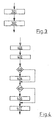
- Figure 4 shows a method in which from the time course of the ion current signal after an injection, a determination of soot takes place.
- measured values of the ion current are advantageously recorded in step 401, after the local maximum has been reached until the exhaust valve opens.
- step 402 the parameters of a Exponential function determined, for example, with the method of parameter identification.
- the parameters of the e-function are determined so that in the measured values based on the curve resulting from the parameters the squares of the deviations of the measured values be minimized by the curve. These error squares are therefore also a measure of how good the measured values can be approximated by an e-function.
- step 403 the determined parameters of the e-function are given with Setpoints compared.
- the determined parameters deviate more than a certain one Amount of associated setpoints, a transition is made to step 404, in which a corresponding identifier is set. If the determined parameters do not exceed one If the amount differs from the corresponding target values, a transition to the step 405.
- step 405 it is checked whether the measured values are represented by the curve resulting from the determined parameters, can approach sufficiently well. It has been shown that with a formation of soot, the measurement curve of the measured ion current of the behavior of a Exponential function deviates. When determining the parameters of an e-function with the Method of parameter identification, this can be detected by the error squares be evaluated. As the detected squares of the squares increase, i. E. if the Error in the determination is greater than a certain value, there is a transition to the Step 406, in which a corresponding identifier is set. Otherwise, a Transition to step 407.
- step 407 an evaluation is carried out if necessary in steps 404 and / or 406 set identifiers. It can be seen that only one of the tests of the steps 403 or 405 can be made.
- step 407 detection of excessive soot formation may then occur. Possibly. Also, the extent of soot formation can be detected.
- the ion current signal is integrated in step 501 and evaluated in terms of area and / or the location and / or height of the maxima of the Ion current signals evaluated. After this evaluation will be at least one of these sizes in step 502 compared to one or more setpoints. Especially if the Height of maxima exceeds certain thresholds or if the areas under the Curves exceed certain thresholds, can be a detection of continuous injection take place in at least one cylinder.
- step 502 If a continuous injection has been detected in step 502, a transition is made to the step 503, in which the injection is prevented at least in the cylinder at a fault has been detected.
- the embodiment of the method proves to be special advantageous in diesel engines whose power supply is realized by the individual Cylinder are connected in an injection process with a pressure reservoir.
- Such Systems are known as common rail systems. If in such a system a valve depends, can be beneficial a continuous injection with a possible damage to the internal combustion engine can be prevented.
Landscapes
- Engineering & Computer Science (AREA)
- Chemical & Material Sciences (AREA)
- Combustion & Propulsion (AREA)
- Mechanical Engineering (AREA)
- General Engineering & Computer Science (AREA)
- Combined Controls Of Internal Combustion Engines (AREA)
- Electrical Control Of Air Or Fuel Supplied To Internal-Combustion Engine (AREA)
- Ignition Installations For Internal Combustion Engines (AREA)
Description
- Fig. 1:
- den Zeitverlauf eines Ionenstromsignals und eines Einspritzsignals und
- Fig. 2-5:
- verschiedene Ausführungsbeispiele von Verfahren zur Auswertung des gemessenen Ionenstromsignals.
Claims (5)
- Verfahren zur Rußbestimmung mittels Auswertung eines Ionenstromsignales einer selbstzündenden Brennkraftmaschine, wobei eine Auswertung eines zeitlichen Verlaufes des Ionenstromsignales (110, 111) nach einer Einspritzung erfolgt,
dadurch gekennzeichnet, daß der zeitliche Verlauf des Ionenstromsignales durch Bestimmung der Parameter einer mit der Zeit fallenden Exponentialfunktion angenähert wird (402, 407). - Verfahren nach Anspruch 1,
dadurch gekennzeichnet, daß die Bestimmung der Parameter der Exponentialfunktion mittels der Methode der kleinsten Fehlerquadrate erfolgt. - Verfahren nach Anspruch 1,
dadurch gekennzeichnet, dass bei Abweichung wenigstens eines der Parameter um mehr als einen bestimmten Betrag von einem vorgegebenen Sollwert (ferner 3,4 104) eine übermäßige Rußbildung erkannt wird. - Verfahren nach Anspruch 1 oder 3,
dadurch gekennzeichnet, daß bei Abweichung der Meßkurve des Ionenstromsignales von dem Verlauf der Exponentialfunktion auf einer übermäßige Rußbildung erkannt wird, wenn diese Abweichung einen bestimmten Wert (405, 406, 407) überschreitet. - Verfahren nach Anspruch 4,
dadurch gekennzeichnet, daß sich die Abweichung der Meßkurve von der Exponentialfunktion aus den Quadraten der Abweichungen der Messwerte von der Exponentialfunktion ergibt.
Priority Applications (1)
| Application Number | Priority Date | Filing Date | Title |
|---|---|---|---|
| EP02018413A EP1258633A3 (de) | 1998-08-22 | 1999-07-10 | Verfahren zur Auswertung eines Ionenstromsignales einer selbstzündenden Brennkraftmaschine |
Applications Claiming Priority (2)
| Application Number | Priority Date | Filing Date | Title |
|---|---|---|---|
| DE19838222 | 1998-08-22 | ||
| DE19838222A DE19838222A1 (de) | 1998-08-22 | 1998-08-22 | Verfahren zur Auswertung eines Ionenstromsignales einer selbstzündenden Brennkraftmaschine |
Related Child Applications (1)
| Application Number | Title | Priority Date | Filing Date |
|---|---|---|---|
| EP02018413A Division EP1258633A3 (de) | 1998-08-22 | 1999-07-10 | Verfahren zur Auswertung eines Ionenstromsignales einer selbstzündenden Brennkraftmaschine |
Publications (2)
| Publication Number | Publication Date |
|---|---|
| EP0982496A1 EP0982496A1 (de) | 2000-03-01 |
| EP0982496B1 true EP0982496B1 (de) | 2003-09-03 |
Family
ID=7878406
Family Applications (2)
| Application Number | Title | Priority Date | Filing Date |
|---|---|---|---|
| EP02018413A Withdrawn EP1258633A3 (de) | 1998-08-22 | 1999-07-10 | Verfahren zur Auswertung eines Ionenstromsignales einer selbstzündenden Brennkraftmaschine |
| EP99113438A Expired - Lifetime EP0982496B1 (de) | 1998-08-22 | 1999-07-10 | Verfahren zur Auswertung eines Ionenstromsignales einer selbstzündenden Brennkraftmaschine |
Family Applications Before (1)
| Application Number | Title | Priority Date | Filing Date |
|---|---|---|---|
| EP02018413A Withdrawn EP1258633A3 (de) | 1998-08-22 | 1999-07-10 | Verfahren zur Auswertung eines Ionenstromsignales einer selbstzündenden Brennkraftmaschine |
Country Status (3)
| Country | Link |
|---|---|
| US (1) | US6279538B1 (de) |
| EP (2) | EP1258633A3 (de) |
| DE (2) | DE19838222A1 (de) |
Families Citing this family (20)
| Publication number | Priority date | Publication date | Assignee | Title |
|---|---|---|---|---|
| DE10008553B4 (de) * | 2000-02-24 | 2009-01-29 | Robert Bosch Gmbh | Verfahren und Vorrichtung zur Auswertung eines Ionenstrom-Sensor-Signals einer Brennkraftmaschine |
| DE10011621A1 (de) * | 2000-03-10 | 2001-09-13 | Delphi Tech Inc | Verfahren zur Regelung der Mehrfacheinspritzung in einem Verbrennungsmotor |
| DE10011622A1 (de) * | 2000-03-10 | 2001-09-13 | Delphi Tech Inc | Verfahren zum Regeln der Verbrennung fossiler Brennstoffe |
| DE10028884A1 (de) * | 2000-06-10 | 2001-12-13 | Volkswagen Ag | Verfahren und Vorrichtung zum Erfassen des Verbrennungsablaufs in einem Verbrennungsmotor |
| US6480781B1 (en) * | 2000-07-13 | 2002-11-12 | Caterpillar Inc. | Method and apparatus for trimming an internal combustion engine |
| DE10221001A1 (de) | 2002-05-11 | 2003-11-27 | Daimler Chrysler Ag | Verfahren und Vorrichtung zur Bestimmung einer Voreinspritzmenge |
| US7055372B2 (en) * | 2002-11-01 | 2006-06-06 | Visteon Global Technologies, Inc. | Method of detecting cylinder ID using in-cylinder ionization for spark detection following partial coil charging |
| US7251571B2 (en) * | 2003-09-05 | 2007-07-31 | Visteon Global Technologies, Inc. | Methods of diagnosing open-secondary winding of an ignition coil using the ionization current signal |
| DE10352222A1 (de) * | 2003-11-08 | 2005-06-09 | Daimlerchrysler Ag | Verfahren zur Steuerung der Abgasrückführrate |
| DE102004042008A1 (de) | 2004-08-31 | 2006-03-02 | Daimlerchrysler Ag | Verfahren zur Bestimmung der Einspritzmenge von Injektoren einer selbstzündenden Brennkraftmaschine |
| DE102005043971A1 (de) | 2005-09-15 | 2007-03-22 | Robert Bosch Gmbh | Verfahren und Vorrichtung zur Überwachung eines Kraftstoffzumesssystems |
| US7603226B2 (en) * | 2006-08-14 | 2009-10-13 | Henein Naeim A | Using ion current for in-cylinder NOx detection in diesel engines and their control |
| DE102007048650B4 (de) * | 2007-10-10 | 2011-06-09 | Audi Ag | Verfahren und Vorrichtung zur Optimierung der Verbrennung von Dieselkraftstoffen mit unterschiedlichen Cetanzahlen in einer Diesel-Brennkraftmaschine |
| US8408191B2 (en) | 2010-06-23 | 2013-04-02 | Delphi Technologies, Inc. | Engine combustion control using ignition dwell |
| WO2012118781A2 (en) * | 2011-02-28 | 2012-09-07 | Wayne State University | Using ion current signal for soot and in-cylinder variable measuring techniques in internal combustion engines and methods for doing the same |
| EP2820580A4 (de) * | 2012-02-28 | 2015-07-29 | Univ Wayne State | Verwendung eines ionenstromsignals für techniken zur messung von motorleistung und -emissionen sowie verfahren dafür |
| EP2900990A4 (de) * | 2012-09-28 | 2016-06-15 | Univ Wayne State | Ionenstromverwendung für verbrennungsresonanzerkennung und -reduktion sowie motorsteuerung |
| US9964093B2 (en) * | 2014-11-26 | 2018-05-08 | Southwest Research Institute | Two-dimensional igniter for testing in-cylinder gas velocity and/or gas composition |
| DE102016217306A1 (de) * | 2016-09-12 | 2018-03-15 | Robert Bosch Gmbh | Verfahren zur Steuerung von Mehrfacheinspritzungen bei einem Einspritzsystem |
| US10082098B2 (en) * | 2016-10-21 | 2018-09-25 | GM Global Technology Operations LLC | Systems and methods for controlling fluid injections |
Family Cites Families (17)
| Publication number | Priority date | Publication date | Assignee | Title |
|---|---|---|---|---|
| US3575146A (en) * | 1969-02-06 | 1971-04-20 | Physics Int Co | Fuel injection system for an internal combustion engine |
| DE2554988C2 (de) * | 1975-12-06 | 1985-01-10 | Robert Bosch Gmbh, 7000 Stuttgart | Verfahren zur Bestimmung der Zusammensetzung des einer Brennkraftmaschine zugeführten Betriebsgemisches bzw. des Verbrennungsablaufs des Betriebsgemisches und Einrichtung zur Durchführung des Verfahrens |
| DE2939690A1 (de) * | 1979-09-29 | 1981-04-16 | Robert Bosch Gmbh, 7000 Stuttgart | Verfahren zur zuendungszeitpunktregelung |
| DE2944834A1 (de) * | 1979-11-07 | 1981-05-27 | Robert Bosch Gmbh, 7000 Stuttgart | Verfahren zur regelung der luftzahl lambda bei einer selbstzuendenden brennkraftmaschine |
| EP0071557B1 (de) * | 1981-07-23 | 1989-05-24 | Ail Corporation | Verfahren und Einrichtung zur Erzeugung eines Verbrennungsbeginnsignal für eine selbszündende Brennkraftmaschine |
| US4760830A (en) * | 1981-07-23 | 1988-08-02 | Ambac Industries, Incorporated | Method and apparatus for controlling fuel injection timing in a compression ignition engine |
| JPS5943934A (ja) * | 1982-09-06 | 1984-03-12 | Nippon Denso Co Ltd | デイ−ゼルエンジンの着火時期制御装置 |
| US4487184A (en) * | 1983-07-07 | 1984-12-11 | Robert Bosch Gmbh | Control of an internal combustion engine with reference to a combustion chamber sensor |
| DE3428371A1 (de) | 1984-08-01 | 1986-02-13 | Robert Bosch Gmbh, 7000 Stuttgart | Verfahren zur messung und regelung von betriebsdaten von verbrennungsmotoren |
| JP3150429B2 (ja) * | 1992-07-21 | 2001-03-26 | ダイハツ工業株式会社 | イオン電流によるリーン限界検出方法 |
| JP2909345B2 (ja) * | 1993-03-23 | 1999-06-23 | 三菱電機株式会社 | 内燃機関制御装置 |
| SE503900C2 (sv) * | 1995-01-18 | 1996-09-30 | Mecel Ab | Metod och system för övervakning av förbränningsmotorer genom detektering av aktuellt blandningsförhållande luft-bränsle |
| JPH09317619A (ja) * | 1996-05-28 | 1997-12-09 | Toyota Motor Corp | 内燃機関の失火検出装置 |
| DE19642654B4 (de) * | 1996-10-16 | 2004-02-05 | Daimlerchrysler Ag | Verfahren zur Regelung der einstellbaren Betriebsparameter einer direkteinspritzenden Brennkraftmaschine |
| JPH10159699A (ja) * | 1996-12-02 | 1998-06-16 | Mitsubishi Electric Corp | 内燃機関の燃焼制御装置 |
| JPH10252542A (ja) * | 1997-03-10 | 1998-09-22 | Toyota Motor Corp | ディーゼルエンジンの燃料噴射量制御装置 |
| JPH1182149A (ja) * | 1997-08-29 | 1999-03-26 | Denso Corp | 内燃機関の燃料噴射制御装置 |
-
1998
- 1998-08-22 DE DE19838222A patent/DE19838222A1/de not_active Withdrawn
-
1999
- 1999-07-10 EP EP02018413A patent/EP1258633A3/de not_active Withdrawn
- 1999-07-10 EP EP99113438A patent/EP0982496B1/de not_active Expired - Lifetime
- 1999-07-10 DE DE59906835T patent/DE59906835D1/de not_active Expired - Lifetime
- 1999-08-23 US US09/382,189 patent/US6279538B1/en not_active Expired - Lifetime
Also Published As
| Publication number | Publication date |
|---|---|
| EP0982496A1 (de) | 2000-03-01 |
| DE59906835D1 (de) | 2003-10-09 |
| DE19838222A1 (de) | 2000-02-24 |
| EP1258633A3 (de) | 2007-11-21 |
| US6279538B1 (en) | 2001-08-28 |
| EP1258633A2 (de) | 2002-11-20 |
Similar Documents
| Publication | Publication Date | Title |
|---|---|---|
| EP0795077B1 (de) | Verfahren und vorrichtung zur überwachung eines kraftstoffzumesssystems | |
| EP0982496A1 (de) | Verfahren zur Auswertung eines Ionenstromsignales einer selbstzündenden Brennkraftmaschine | |
| DE102005043017B4 (de) | Common-Rail-Kraftstoffeinspritzsystem | |
| DE19749817B4 (de) | Vorrichtung und Verfahren zur Ermittlung des Spritzbeginns | |
| EP1028235B1 (de) | Verfahren zur Steuerung einer Brennkraftmaschine mit einem Abgasnachbehandlungssystem | |
| EP1303691B1 (de) | Verfahren und vorrichtung zur fehlererkennung bzw. diagnose bei einem klopfsensor | |
| DE69701738T2 (de) | Kalibrierungsverfahren für ein elektronisches kraftstoffeinspritzsystem | |
| DE10008553B4 (de) | Verfahren und Vorrichtung zur Auswertung eines Ionenstrom-Sensor-Signals einer Brennkraftmaschine | |
| EP0940571B1 (de) | Verfahren und Vorrichtung zum Steuern der Kraftstoffeinspritzung | |
| DE10159017A1 (de) | Verfahren und Vorrichtung zur Steuerung einer Brennkraftmaschine | |
| DE19626690B4 (de) | Verfahren und Vorrichtung zur Überwachung eines Kraftstoffzumeßsystems einer Brennkraftmaschine | |
| DE102020210226A1 (de) | Verfahren zum Steuern einer Ölpumpe eines Fahrzeugs | |
| DE10056477B9 (de) | Brennstoffeinspritzvorrichtung für eine Brennkraftmaschine | |
| EP3033513A1 (de) | Verfahren zur injektorindividuellen diagnose einer kraftstoff-einspritzeinrichtung und brennkraftmaschine mit einer kraftstoff-einspritzeinrichtung | |
| DE102009007365B4 (de) | Fehleranalyseverfahren und Fehleranalysevorrichtung für einen Verbrennungsmotor | |
| DE19923475C2 (de) | Motorsteuerung mit Abgasrückführung und Verfahren zur Ermittlung des korrekten Funktionierens des AGR-Systems in einem Kraftfahrzeug | |
| DE19620038B4 (de) | Verfahren und Vorrichtung zur Überwachung eines Kraftstoffzumeßsystems | |
| DE102004054778A1 (de) | Einspritzmengensteuerungsvorrichtung für eine Brennkraftmaschine | |
| DE102018101773B4 (de) | Verfahren und Vorrichtung zur Wassereinspritzung | |
| EP1502018B1 (de) | Verfahren zum betreiben eines verbrennungsmotors | |
| DE19641942A1 (de) | Verfahren und Vorrichtung zur Fehlererkennung bei einer Brennkraftmaschine | |
| DE19810523B4 (de) | Vorrichtung zur Erfassung ionalen Stroms für eine Brennkraftmaschine | |
| DE19901066C1 (de) | Verfahren zur Erkennung von durchlaßverringernden Veränderungen in einem Abgaskatalysatorkörper | |
| EP1132605B1 (de) | Verfahren zum Bestimmen des Beginns einer Verbrennung im Zylinder eines Verbrennungsmotors | |
| DE102008008384A1 (de) | Verfahren zur Identifikation von Zylindern einer Brennkraftmaschine bei Auftreten von zylinderindividuellen Ereignissen |
Legal Events
| Date | Code | Title | Description |
|---|---|---|---|
| PUAI | Public reference made under article 153(3) epc to a published international application that has entered the european phase |
Free format text: ORIGINAL CODE: 0009012 |
|
| AK | Designated contracting states |
Kind code of ref document: A1 Designated state(s): DE FR GB IT |
|
| AX | Request for extension of the european patent |
Free format text: AL;LT;LV;MK;RO;SI |
|
| 17P | Request for examination filed |
Effective date: 20000125 |
|
| AKX | Designation fees paid |
Free format text: DE FR GB IT |
|
| 17Q | First examination report despatched |
Effective date: 20020423 |
|
| GRAH | Despatch of communication of intention to grant a patent |
Free format text: ORIGINAL CODE: EPIDOS IGRA |
|
| GRAS | Grant fee paid |
Free format text: ORIGINAL CODE: EPIDOSNIGR3 |
|
| GRAA | (expected) grant |
Free format text: ORIGINAL CODE: 0009210 |
|
| AK | Designated contracting states |
Kind code of ref document: B1 Designated state(s): DE FR GB IT |
|
| REG | Reference to a national code |
Ref country code: GB Ref legal event code: FG4D Free format text: NOT ENGLISH |
|
| REF | Corresponds to: |
Ref document number: 59906835 Country of ref document: DE Date of ref document: 20031009 Kind code of ref document: P |
|
| GBT | Gb: translation of ep patent filed (gb section 77(6)(a)/1977) |
Effective date: 20040112 |
|
| ET | Fr: translation filed | ||
| PLBE | No opposition filed within time limit |
Free format text: ORIGINAL CODE: 0009261 |
|
| STAA | Information on the status of an ep patent application or granted ep patent |
Free format text: STATUS: NO OPPOSITION FILED WITHIN TIME LIMIT |
|
| 26N | No opposition filed |
Effective date: 20040604 |
|
| REG | Reference to a national code |
Ref country code: FR Ref legal event code: CD Ref country code: FR Ref legal event code: CA |
|
| PGFP | Annual fee paid to national office [announced via postgrant information from national office to epo] |
Ref country code: IT Payment date: 20110721 Year of fee payment: 13 |
|
| REG | Reference to a national code |
Ref country code: GB Ref legal event code: 732E Free format text: REGISTERED BETWEEN 20120503 AND 20120509 |
|
| REG | Reference to a national code |
Ref country code: FR Ref legal event code: TP Owner name: BURANI CONSULTING LIMITED LIABILITY COMPANY, US Effective date: 20120427 |
|
| REG | Reference to a national code |
Ref country code: DE Ref legal event code: R081 Ref document number: 59906835 Country of ref document: DE Owner name: BURANI CONSULTING LIMITED LIABILITY COMPANY, US Free format text: FORMER OWNER: DAIMLER AG, 70327 STUTTGART, DE Effective date: 20120418 |
|
| PGFP | Annual fee paid to national office [announced via postgrant information from national office to epo] |
Ref country code: GB Payment date: 20120625 Year of fee payment: 14 |
|
| PGFP | Annual fee paid to national office [announced via postgrant information from national office to epo] |
Ref country code: DE Payment date: 20120731 Year of fee payment: 14 |
|
| PG25 | Lapsed in a contracting state [announced via postgrant information from national office to epo] |
Ref country code: IT Free format text: LAPSE BECAUSE OF NON-PAYMENT OF DUE FEES Effective date: 20120710 |
|
| PGFP | Annual fee paid to national office [announced via postgrant information from national office to epo] |
Ref country code: FR Payment date: 20130712 Year of fee payment: 15 |
|
| GBPC | Gb: european patent ceased through non-payment of renewal fee |
Effective date: 20130710 |
|
| REG | Reference to a national code |
Ref country code: DE Ref legal event code: R119 Ref document number: 59906835 Country of ref document: DE Effective date: 20140201 |
|
| PG25 | Lapsed in a contracting state [announced via postgrant information from national office to epo] |
Ref country code: GB Free format text: LAPSE BECAUSE OF NON-PAYMENT OF DUE FEES Effective date: 20130710 Ref country code: DE Free format text: LAPSE BECAUSE OF NON-PAYMENT OF DUE FEES Effective date: 20140201 |
|
| REG | Reference to a national code |
Ref country code: FR Ref legal event code: ST Effective date: 20150331 |
|
| PG25 | Lapsed in a contracting state [announced via postgrant information from national office to epo] |
Ref country code: FR Free format text: LAPSE BECAUSE OF NON-PAYMENT OF DUE FEES Effective date: 20140731 |