EP0980716B1 - Beschichtungsvorrichtung - Google Patents
Beschichtungsvorrichtung Download PDFInfo
- Publication number
- EP0980716B1 EP0980716B1 EP98905755A EP98905755A EP0980716B1 EP 0980716 B1 EP0980716 B1 EP 0980716B1 EP 98905755 A EP98905755 A EP 98905755A EP 98905755 A EP98905755 A EP 98905755A EP 0980716 B1 EP0980716 B1 EP 0980716B1
- Authority
- EP
- European Patent Office
- Prior art keywords
- works
- hangers
- carriers
- conveyor
- track
- Prior art date
- Legal status (The legal status is an assumption and is not a legal conclusion. Google has not performed a legal analysis and makes no representation as to the accuracy of the status listed.)
- Expired - Lifetime
Links
- 239000011248 coating agent Substances 0.000 title claims description 78
- 238000000576 coating method Methods 0.000 title claims description 78
- 238000001035 drying Methods 0.000 claims description 103
- 239000000969 carrier Substances 0.000 claims description 90
- 238000003860 storage Methods 0.000 claims description 72
- 239000000463 material Substances 0.000 claims description 6
- 238000007598 dipping method Methods 0.000 claims description 2
- 238000002203 pretreatment Methods 0.000 claims 7
- 238000004070 electrodeposition Methods 0.000 description 30
- 238000009434 installation Methods 0.000 description 11
- 230000003247 decreasing effect Effects 0.000 description 9
- 230000015572 biosynthetic process Effects 0.000 description 2
- 238000004140 cleaning Methods 0.000 description 2
- 238000005238 degreasing Methods 0.000 description 2
- 238000004519 manufacturing process Methods 0.000 description 2
- 239000000126 substance Substances 0.000 description 2
- 238000005260 corrosion Methods 0.000 description 1
- 230000007797 corrosion Effects 0.000 description 1
- 238000003618 dip coating Methods 0.000 description 1
- 238000010981 drying operation Methods 0.000 description 1
- 230000000694 effects Effects 0.000 description 1
- 238000005304 joining Methods 0.000 description 1
- 238000000034 method Methods 0.000 description 1
- 239000003973 paint Substances 0.000 description 1
Images


Classifications
-
- B—PERFORMING OPERATIONS; TRANSPORTING
- B05—SPRAYING OR ATOMISING IN GENERAL; APPLYING FLUENT MATERIALS TO SURFACES, IN GENERAL
- B05C—APPARATUS FOR APPLYING FLUENT MATERIALS TO SURFACES, IN GENERAL
- B05C13/00—Means for manipulating or holding work, e.g. for separate articles
- B05C13/02—Means for manipulating or holding work, e.g. for separate articles for particular articles
-
- B—PERFORMING OPERATIONS; TRANSPORTING
- B05—SPRAYING OR ATOMISING IN GENERAL; APPLYING FLUENT MATERIALS TO SURFACES, IN GENERAL
- B05C—APPARATUS FOR APPLYING FLUENT MATERIALS TO SURFACES, IN GENERAL
- B05C3/00—Apparatus in which the work is brought into contact with a bulk quantity of liquid or other fluent material
- B05C3/02—Apparatus in which the work is brought into contact with a bulk quantity of liquid or other fluent material the work being immersed in the liquid or other fluent material
- B05C3/09—Apparatus in which the work is brought into contact with a bulk quantity of liquid or other fluent material the work being immersed in the liquid or other fluent material for treating separate articles
- B05C3/10—Apparatus in which the work is brought into contact with a bulk quantity of liquid or other fluent material the work being immersed in the liquid or other fluent material for treating separate articles the articles being moved through the liquid or other fluent material
-
- B—PERFORMING OPERATIONS; TRANSPORTING
- B05—SPRAYING OR ATOMISING IN GENERAL; APPLYING FLUENT MATERIALS TO SURFACES, IN GENERAL
- B05C—APPARATUS FOR APPLYING FLUENT MATERIALS TO SURFACES, IN GENERAL
- B05C9/00—Apparatus or plant for applying liquid or other fluent material to surfaces by means not covered by any preceding group, or in which the means of applying the liquid or other fluent material is not important
- B05C9/08—Apparatus or plant for applying liquid or other fluent material to surfaces by means not covered by any preceding group, or in which the means of applying the liquid or other fluent material is not important for applying liquid or other fluent material and performing an auxiliary operation
- B05C9/14—Apparatus or plant for applying liquid or other fluent material to surfaces by means not covered by any preceding group, or in which the means of applying the liquid or other fluent material is not important for applying liquid or other fluent material and performing an auxiliary operation the auxiliary operation involving heating or cooling
-
- B—PERFORMING OPERATIONS; TRANSPORTING
- B05—SPRAYING OR ATOMISING IN GENERAL; APPLYING FLUENT MATERIALS TO SURFACES, IN GENERAL
- B05B—SPRAYING APPARATUS; ATOMISING APPARATUS; NOZZLES
- B05B13/00—Machines or plants for applying liquids or other fluent materials to surfaces of objects or other work by spraying, not covered by groups B05B1/00 - B05B11/00
- B05B13/02—Means for supporting work; Arrangement or mounting of spray heads; Adaptation or arrangement of means for feeding work
- B05B13/0221—Means for supporting work; Arrangement or mounting of spray heads; Adaptation or arrangement of means for feeding work characterised by the means for moving or conveying the objects or other work, e.g. conveyor belts
- B05B13/0264—Overhead conveying means, i.e. the object or other work being suspended from the conveying means; Details thereof, e.g. hanging hooks
-
- B—PERFORMING OPERATIONS; TRANSPORTING
- B05—SPRAYING OR ATOMISING IN GENERAL; APPLYING FLUENT MATERIALS TO SURFACES, IN GENERAL
- B05C—APPARATUS FOR APPLYING FLUENT MATERIALS TO SURFACES, IN GENERAL
- B05C9/00—Apparatus or plant for applying liquid or other fluent material to surfaces by means not covered by any preceding group, or in which the means of applying the liquid or other fluent material is not important
- B05C9/08—Apparatus or plant for applying liquid or other fluent material to surfaces by means not covered by any preceding group, or in which the means of applying the liquid or other fluent material is not important for applying liquid or other fluent material and performing an auxiliary operation
- B05C9/10—Apparatus or plant for applying liquid or other fluent material to surfaces by means not covered by any preceding group, or in which the means of applying the liquid or other fluent material is not important for applying liquid or other fluent material and performing an auxiliary operation the auxiliary operation being performed before the application
-
- B—PERFORMING OPERATIONS; TRANSPORTING
- B05—SPRAYING OR ATOMISING IN GENERAL; APPLYING FLUENT MATERIALS TO SURFACES, IN GENERAL
- B05C—APPARATUS FOR APPLYING FLUENT MATERIALS TO SURFACES, IN GENERAL
- B05C9/00—Apparatus or plant for applying liquid or other fluent material to surfaces by means not covered by any preceding group, or in which the means of applying the liquid or other fluent material is not important
- B05C9/08—Apparatus or plant for applying liquid or other fluent material to surfaces by means not covered by any preceding group, or in which the means of applying the liquid or other fluent material is not important for applying liquid or other fluent material and performing an auxiliary operation
- B05C9/12—Apparatus or plant for applying liquid or other fluent material to surfaces by means not covered by any preceding group, or in which the means of applying the liquid or other fluent material is not important for applying liquid or other fluent material and performing an auxiliary operation the auxiliary operation being performed after the application
Definitions
- the present invention concerns a coating facility adapted for applying pretreatment and coating to works such as car bodies while conveying them by an overhead conveyor, then transferring them to a floor conveyor, drying and then conveying them to a succeeding step after completion of the drying.
- Fig. 5 and Fig. 6 show a running state and a storage state of an existent coating facility for conducting electrodeposition coating which comprises, along an overhead conveyor 42 formed in a circulation track 41, a loading device 43 for loading works W conveyed from the preceding step to hangers H each at a predetermined loading position P 1 , a pretreatment device 44 for applying pretreatment such as cleaning, degreasing and chemical formation to the surface of the works W loaded by the loading device 43, an electrodeposition coating device 45 for forming an electrodeposition coating film on the surface of the works W completed with the pretreatment by the pretreatment device 44, and a transfer device 48 for down loading the works W from the hangers H after completion of the electrodeposition coating in the electrodeposition coating device 45 and transferring them to carriers T, at a predetermined transferring position P 2 , to a floor conveyor 47 running in a drying furnace 46 in this order.
- a pretreatment device 44 for applying pretreatment such as cleaning, degreasing and chemical formation to the surface of the works W loaded by the loading device 43
- the floor conveyor 47 constitutes a circulation track 47a for conveying the carriers T to which the works W are transferred at a transferring position P 2 into the drying furnace 46, conveying the works W after completion of drying to the succeeding step while loading them as they are on the carriers T and returning the carriers T emptied in the succeeding stage again to the transferring position P 2 .
- the circulation track 47a of the floor conveyor 47 that returns from the succeeding step is branched to form a reserved carrier storage track 47b for storing the emptied carriers T by the number of the works W being conveyed by the overhead conveyor 42 but not yet conveyed to the drying furnace 46
- the circulation track 47a from the exit of the drying furnace 46 to the succeeding step is branched to form a carrier storage track 47c for storing all the works W which are being conveyed by the overhead conveyor 42 and the floor conveyor 47 in a state loaded on the carriers T.
- the carrier storage track 47c is adapted such that, at the instance the conveyance of the works from the preceding step and the conveyance to the succeeding step are stopped, it completes drying for the works W conveying by the floor conveyor 47 and stores them while loading on the carriers T as they are, applies pretreatment and completes electrodeposition coating of the works W conveying by the overhead conveyor 42, transfers them to the carriers T stored in the reserved carrier storage track 47b, conveys them successively to the drying furnace 46, completes drying and then stores them while loading as they are on the carriers T.
- the overhead conveyor 42 is branched to form a looped empty hanger storage track 41a from the circulation track 41 that returns from the transferring position P 2 to the loading position P 1 for storing hangers H which are emptied after transferring the works to the carriers T of the floor conveyor 47, when the conveyance of the works W from the preceding step is stopped, so that the empty hangers H may be prevented from corrosion caused when left in the pretreatment device 44 or the electrodeposition coating device 45, and so that the empty hangers H can be delivered immediately to the loading position P 1 as soon as the conveyance of the works W from the preceding step is started.
- the hangers are circulately run by the overhead conveyor 42, pretreatment is applied in the pretreatment device 44 while conveying the works W loaded by the loading device 43, electrodeposition coating is conducted in the electrodeposition coating device 45, the works W are re-transferred subsequently by the transfer device 48 to the carriers T of the floor conveyor 47, and the emptied hangers H are returned again to the loading position P 1 to which succeeding works W are loaded and treated continuously.
- the floor conveyor 47 is adapted such that empty carriers T returning from the succeeding step along the circulation track 47a or the reserved carriers T stored in the reserved carrier storage track 47b are conveyed to the transferring position P 2 , the works W transferred by the transfer device 48 to the carriers T are conveyed into the drying furnace 46 and conveyed as they are to the succeeding step after the completion of the drying.
- the conveying lines between each of the steps are stopped and conveyance from the preceding step and conveyance to the succeeding step of the works W are stopped, the works W in the drying furnace 46 are stored being loaded as they are on the carriers T in the carrier storage track 47c, while the works W in the pretreatment device 44 and the electrodeposition coating device 45 are completed with the pretreatment and the electrodeposition coating, transferred by the transfer device 48 to the reserved carriers T on the floor conveyor 47, dried in the drying furnace 46 and then stored while being loaded as they are on the reserved carriers T in the carrier storage track 47c, while the hangers H emptied after transferring the works to the carriers T are stored in the empty hanger storage track 41a.
- the empty hangers H stored in the empty hanger storage track 41a are delivered to the circulation track 41 of the overhead conveyor 42 and caused to stand-by at the loading position P 1 and the coating operation is started by successively loading the works W conveyed form the preceding step and, at the same time, the works W stored in the carrier storage track 47c are successively conveyed together with the carriers T to the succeeding step, and the empty carriers T returned from the succeeding step are delivered to and stored in the reversed carrier storage track 47b successively till the leading work W conveyed by the overhead conveyor 42 reaches the transferring position P 2 .
- the entire length of the empty hanger storage track 41a is: 49 x 7 ⁇ 350 m
- the entire length of the reserved carrier storing track is: 49 x 7 ⁇ 350 m
- the entire length of the carrier storage track 47c is: (49 + 24) x 7 ⁇ 520m, so that the total extension of all the storage tracks 41a, 47b and 47c reaches 1200 to 1300 m.
- the carriers T bring heat in the drying furnace 46 to the outside and are returned being cooled to a room temperature after handing the works W to the succeeding step and they are heated again when entered into the drying furnace 46, so that a great amount of heat in the furnace is lost to result in a problem that a large amount of heat in the drying furnace 46 is consumed to increase the running cost.
- JP04-114769 discloses a coating facility for car bodies (works), which are from a preceding process step facility in the scheduled sequence for manufacturing, which is not related to the colour of the paint to be coated.
- the works are sorted according to the colour in an order adjustment lane, conveyed to the coating step, and stored in a re-order adjustment lane, from which they are rearranged in the original manufacturing sequence.
- This facility can not finish drying the works, when the conveyor is being stopped and can not store the dried works.
- the present invention provides a coating facility comprising, along an overhead conveyor formed in a circulation track, a loading device for loading works conveyed from a preceding step at a predetermined loading position to hangers of the overhead conveyor, a pretreatment device for applying pretreatment to the surface of the works loaded by the loading device, a coating device for dipping the works completed with the pretreatment in the pretreatment device into a coating material to deposit the coating material on the surface thereof, and a lifting device for down loading the works from the hangers deposited with the coating material in the coating device and transferring them at a predetermined transferring position to carriers of a floor conveyor that runs in a drying furnace that are arranged in this order, and in which the pretreatment and the coating are applied while the works are conveyed on the overhead conveyor, then the works are transferred to the carries of the floor conveyor, dried during conveyance and then conveyed to a succeeding step after the completion of drying, wherein the floor conveyor is formed in a circulation track that runs in the drying furnace, passes from the exit of
- the works conveyed from the preceding step are loaded to the hangers of the overhead conveyor at a loading position, the works are pretreated at the surface by the pretreatment device and formed with a coating film on the surface thereof by the coating device while being conveyed by the overhead conveyor, transferred to the carriers of the floor conveyor at a transferring position, entered into the drying furnace and dried, re-transferred again at a re-transferring position to the hangers of the overhead conveyor, unloaded each at an unloading position from the hangers and conveyed to the succeeding step.
- the floor conveyor is formed as the circulation track that runs in the drying furnace, passes from the exit of the drying furnace through the re-transferring position and the transferring position and returns to the entrance of the dry furnace, in which the carriers, upon getting out of the drying furnace, pass through the re-transferring position and the transferring position and directly enters into the drying furnace without running to the succeeding step, so that they are caused to run circulately in the drying furnace again before being cooled to a room temperature. Accordingly, the amount of heat in the drying furnace is less deprived by the carriers to decrease the running cost and, since the entire length of the floor conveyor is shortened and number of the carriers is also reduced, the installation cost can be decreased.
- the first and the second storage tracks have such a length as capable of storing all of the works during conveyance in each of the conveyors when the conveying lines between each of the steps are stopped, and it may suffice that there are provided hangers by a predetermined number for pretreatment and coating of the works and carriers by a predetermined number for running in the drying furnace, so that no additional hangers or carriers for storage are required at all, a space for storing empty carriers is saved at all and a space for storing work-loaded carriers is also reduced and the number of the carriers is also reduced remarkably and, accordingly, the space utilization efficiency can be improved remarkably and, at the same time, facilities required for storage can be reduced to decrease the installation cost.
- the carrier T stored in the second storage track is delivered from the delivery side to the circulation track of the floor conveyor, the work loaded on the carrier is re-transferred to the hanger at the re-transferring position, the emptied carrier is sent to the transferring position, the work suspended from the succeeding hanger is transferred to the carrier and entered to the drying furnace, while the emptied hanger is conveyed to the re-transferring position.
- the hanger emptied at the transferring position is sent to the re-transferring position, and the work stored in the second storage track is re-transferred to the hanger at the re-transferring position and subsequently, the works delivered out of the drying furnace are re-transferred to the hangers and conveyed to the unloading position, the emptied hangers are conveyed again to the loading position, and the works conveyed from the preceding step are loaded, and then the coating operation is continued.
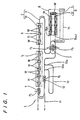
- Fig. 1 is a plan view showing a running state of a coating facility according to the present invention
- Fig. 2 is a plan view showing a storage state thereof
- Fig. 3 is a plan view showing a running state of another embodiment according to the present invention
- Fig. 4 is a plan view showing a storage state thereof
- Fig. 5 is a plan view showing a running state of an prior art apparatus
- Fig. 6 is a plan view showing a storage state of the prior art.
- a coating facility 1 shown in Fig. 1 and Fig. 2 has an overhead conveyor 2 formed in a circulation track 3 for conveying works W while suspending them upstairs by hangers H, in which are arranged, along the overhead conveyor 2, a loading device 4 for loading the works W conveyed from a preceding step to hangers H each at a loading position P 1 , a pretreatment device 5 for applying pretreatment such as cleaning, degreasing and chemical formation to the surface of the works W loaded by the loading device 4, an electrodeposition coating device 6 for forming an electrodeposition coating film on the surface of the works W downstairs after completion of the pretreatment in the pretreatment device 5 and a lifting device 7 for descending the works W after completion of electrodeposition coating by the electrodeposition coating device 6 each at a transferring position P 2 .
- pretreatment device 5 for applying pretreatment such as cleaning, degreasing and chemical formation to the surface of the works W loaded by the loading device 4
- an electrodeposition coating device 6 for forming an electrodeposition coating film on the surface of the works W downstairs after completion of the
- a floor conveyor 9 for running carriers T for loading works W at a predetermined interval is formed in a circulation track 10 that runs in the drying furnace 8, goes from the exit 8out of the drying furnace, around the periphery of the lifting device 7 and returns to the entrance 8in of the drying furnace.
- the lifting device 7 has a transferring position P 2 at the front and is adapted to down load the works W after completion of the electrodeposition coating by the electrodeposition coating device 6 from the hangers H of the overhead conveyor 2 in the upstairs and re-transfer them to the carriers T in the floor conveyor 9 laid in the downstairs, lift up the works W after completion of the drying in the drying furnace 8 from the carriers T on the floor conveyor 9 in the downstairs and re-transfer them on the hangers H of the overhead conveyor 2 in the upstairs each at a re-transferring position P 3 at the back thereof.
- the circulation track 3 for the overhead conveyor 2 is formed so as to pass the transferring position P 2 and the re-transferring position P 3 , while going around the periphery of the lifting device 7 and return to the loading position P 1 , and an unloading device 12 is disposed between the re-transferring position P 3 and the loading position P 1 for descending the works W re-transferred to the hangers H each at the re-transferring position P 3 from the overhead conveyor 2 at a predetermined unloading position P 4 and handing them to a conveyor 11 for conveying them to the succeeding step.
- a looped first storage track 13 formed to such a length as capable of storing the works W, each in a state being suspended from the hangers H, by a predetermined number (for example 49) of the hangers H to be conveyed on the circulation track 3 for the overhead conveyor 2 is laid such that a pull-in side 13a and a delivery side 13b thereof are branched from and joined with the circulation track 3 between the re-transferring position P 3 and the unloading position P 4 of the overhead conveyor 2.
- a second storage track 14 formed to such a length as capable of storing carriers T running on the circulation track 10 for the floor conveyor 9 in a state of loading the works W by a predetermined number (for example, 24) is formed while being branched from the circulation track 10 at a predetermined position between the exit 8out of the drying furnace and the re-transferring position P 3 .
- Fig. 1 shows a running state where the conveying lines between each of the steps in a factory are in operation, in which the surface of the works W is pretreated in the pretreatment device 5 and an electrodeposition film is formed on the surface of the works W in the electrodeposition device 6 while the works W loaded to the hangers H of the overhead conveyor 2 each at the loading position P 1 are conveyed in the upstairs during the conveyance of the works W from a preceding step and to the succeeding step.
- the works W are down loaded from the hangers H of the overhead conveyor 2 by the lifting device 7, transferred to the carriers T of the floor conveyor 9 in the upstairs, entered into and dried in the dry furnace 8, then conveyed out of the drying furnace and lifted up by the lifting device 7 at the re-transferring position P 3 , and re-transferred again to the hangers H of the overhead conveyor 2, then conveyed to the unloading position P 4 , unloaded from the overhead conveyor 2 by the unloading device 12 and handed to the conveyor 11 for conveying them to the succeeding step.
- the floor conveyor 9 is formed as the circulation track 10 that runs in the drying furnace 8, goes from the exit 8out of the drying furnace around the lifting device 7 and immediately returns to the entrance 8in of the drying furnace, and the carriers T run almost in the drying furnace 8 and conveyed out of the drying furnace only for transferring/re-transferring the works W relative to the overhead conveyor 2, and the carriers T are not run to the succeeding step and the circulation track 10 laid outside the drying furnace 8 can be shortened, so that the carriers T run inside the drying furnace 8 again before being cooled to a room temperature.
- the installation cost can also be decreased.
- Fig. 2 shows a storage state when the operation for one day is completed and the conveying lines between each of the steps are stopped.
- all the works W conveyed by each of the conveyors 2 and 9 are stored on the first and the second storage tracks 13 and 14, after completion of drying for those under drying in the drying furnace 8, after transfer to the carriers T of the floor conveyor 9 each at the transferring position P 2 and completion of drying in the drying furnace 8 for those during electrodeposition coating in the electrodeposition coating device 6, and after completion of the electrodeposition coating by the electrodeposition coating device 6, transfer to the carriers T of the floor conveyor 9 each at the transferring position P 2 and completion of drying in the drying furnace 8 for those during pretreatment in the pretreatment device 5.
- preceding 49 works W after completion of drying are successively re-transferred to the hangers H of the overhead conveyor each at the re-transferring position P 3 and entered from the pull-in side 13a in a state being suspended from the hangers H and stored therein.
- the first storage track 13 requires the distance of 49 x 7 m ⁇ 350 m for storing the 49 works W
- the second storage track requires the distance of 24 x 7 m ⁇ 170 m for storing 24 works W. Accordingly, it may suffice to ensure about 520 m for the total extension, and the space for storing empty carriers required for storage when the entire works W are loaded on the carriers is not necessary at all, and since the space for storing the carriers in a state of loading the works is reduced, the total extension of the storage track is about 1/2 of that in the existent coating facility, thereby enabling to remarkably improve the space utilization efficiency.
- hangers H it is necessary for the hangers H by the number of 49 and the carriers T by the number of 24, but since they are the minimum number that has to be used for pretreatment, electrodeposition coating and drying of the works W, it is not necessary to provide additional hangers and carriers for storing the works, thereby enabling to decrease the installation cost.
- the hangers H stored in the first storage track 13 are successively delivered to the circulation track 3 of the overhead conveyor 2 and conveyed to the unloading position P 4 , and the works W are unloaded from the hangers H of the overhead conveyor 2 each at the unloading device P 4 and handed to the conveyor 11 for conveying them to the succeeding step, while the emptied hangers H are conveyed to the loading position P 1 .
- the carrier T stored in the second storage track 14 is delivered to the circulating track 10 for the floor conveyor 9, the work W loaded on the carrier T is re-transferred to the hanger H at the re-transferring position P 3 , then the emptied carrier T is sent to the transferring position P 2 , then the work W suspended on the succeeding hanger H is transferred successively to the carrier T and entered into the drying furnace 8, while the emptied hanger H is conveyed to the re-transferring position P 3 .
- the hangers H emptied at the transferring position P 2 are sent to the re-transferring position P 3
- the works W stored in the second storage track 14 are re-transferred to the hangers H each at the re-transferring position P 3
- the works W conveyed out of the drying furnace 8 are subsequently re-transferred to the hangers H and sent to the unloading position P 4
- the emptied hangers H are conveyed again to the loading position P 1
- the works W conveyed from the preceding step are loaded and then the coating operation is continued.
- Fig. 3 is a plan view showing a running state of another embodiment according to the present invention
- Fig. 4 is a plan view showing a storage state. Identical portions with those in Figs 1 and 2 carry same references, with detailed explanations being omitted.
- a second storage track 15 is formed in a looped-shape, in which a pull-in side 15a is branched from a circulation track 3 between a re-transferring position P 3 and an unloading position P 4 of an overhead conveyor 2 and a delivery side 15b is joined with the circulation track 3 before the re-transferring position P 3 of the overhead conveyor 2.
- the second storage track 15 has reserved hangers Hs by the number (for example 24) of the carriers T of the floor conveyor 9 and is determined to such a length as capable of storing the works W in a state they are suspended from the reserved hangers Hs.
- preceding 49 sets of works W after completion of drying are successively re-transferred to the hangers H of the overhead conveyors 2 at the re-transferring position P 3 and entered from the pull-in side 13a in a state being suspended from the hangers H and stored in a first storage track 13.
- succeeding 24 sets of works W after completion of drying are re-transferred to the reserved hangers Hs delivered from the delivery side 15b thereof to the re-transferring position P 3 of the circulation track 3 and entered from the pull-in side 15a in a state being suspended from the reserved hangers Hs and stored in the second storage track 15.
- the works W stored in the first storage track 13 are handed to the conveyor 11 at the unloading position P 4 and conveyed to the succeeding step, and then the hangers H stored in the second storage track 15 are successively delivered from the delivery side 15b to the circulation track 3 for the overhead conveyor 2 and the hangers H are sent to the unloading position P 4 directly or by way of the first storage track 13 to unload the works W, and then sent to the loading position P 1 .
- the emptied handers H are successively sent to the second storage track 15, and the empty hangers H by the number for the reserved hangers Hs are stored as reserved hangers Hs and succeeding hangers H, after transfer to the carriers T of the floor conveyor 9 at the transferring position P 2 , are re-transferred with the works W conveyed from the drying furnace 8 each at the re-transferring position P 3 , and then conveyed to the unloading position P 4 , and further conveyed to the loading position P 1 to load the works conveyed from the preceding step, and the coating operation is continued.
- the works W are stored in a state where they are suspended from the hangers H, not only the space can be saved by so much, but also the space for storing the empty carriers and the space for storing the work-loaded carriers are not necessary at all, and since the number of the carries is greatly reduced, the space utilization efficiency can be improved outstandingly and, at the same time, equipments required for the storage can be reduced to decrease the installation cost.
- the number of the hangers increased for the storage is only 24 for the reserved hangers Hs. Further, it may suffice to provide the carriers T by the number of 24 required for drying the works W and, although the number of the hangers is increased by 24 compared with a coating facility of storing all the works W being placed on the carriers, since the number of the carriers is decreased by 49, the installation cost is decreased as a whole.
- the storage tracks 13 and 15 are not restricted to a case of forming them to separate loops but it may be applicable also to a case, for example, of making the pull-in side 13a and 15a in common, branching the track at the midway and joining the delivery side 13a and 15b separately to the circulation track 3 for the overhead conveyor respectively thereby making a portion thereof to be in common.
- the space for storing the empty carriers is saved upon storing an identical number of works, to reduce the space for storing the work-loaded carriers and the number of required carries is greatly decreased, the space utilizing efficiency can be improved outstandingly and, at the same time, equipments required for storage can be reduced to decrease the installation cost, as well as since the floor conveyor is formed such that carriers running in the drying furnace are returned immediately into the drying furnace without conveying the works as far as the succeeding step, it provides an excellent effect capable of economizing the amount of heat consumption in the drying furnace to decrease the running cost.
- a coating facility such as a coating facility for car bodies adapted to conduct pretreatment, coating and drying while conveying works and send them to the succeeding step after the completion of drying, in which works during pretreatment, coating, drying are processed as far as drying when the conveying lines between each of the steps are stopped after the completion for one day's operation, and stored in a state completed with drying.
Claims (2)
- Beschichtungsvorrichtung, umfassend längs eines als Umlaufbahn (3) ausgebildeten Deckenförderers (2)- eine Beladungsvorrichtung (4) zum Aufladen von Werkstücken (W), die von einem vorangehenden Schritt herangefördert werden, auf Aufhänger (H) des Deckenförderers (2) an einer vorbestimmten Beladeposition (P1),- eine Vorbehandlungseinrichtung (5) zum Anbringen einer Vorbehandlung auf die Oberfläche der von der Beladungsvorrichtung (4) aufgeladenen Werkstücke (W),- eine Beschichtungsvorrichtung (6) zum Eintauchen der in der Vorbehandlungseinrichtung mit der Vorbehandlung versehenen Werkstücke (W) in ein Beschichtungsmaterial, um dieses auf der Oberfläche der Werkstücke abzuscheiden,- einen Trockenofen (8) zum Trocknen der beschichteten Werkstücke,- ferner umfassend eine Hebevorrichtung zum Abladen der in der Beschichtungsvorrichtung (6) mit dem Beschichtungsmaterial beschichteten Werkstücke (W) von den Aufhängern (H) und Übergeben dieser Werkstücke an einer vorbestimmten Übergabeposition (P2) an Träger (T) eines in den Trockenofen (8) führenden Flurförderers (9), wobei die Träger in dieser Reihenfolge angeordnet sind, und wobei in dieser Beschichtungsvorrichtung die Vorbehandlung und die Beschichtung aufgetragen werden, während die Werkstücke (W) vom Deckenförderer (2) gefördert werden, die Werkstücke dann auf die Träger (T) des Flurförderers (9) übergeben werden, während des Förderns getrocknet und dann nach Abschluss der Trocknung zu einem nachfolgenden Schritt weitergefördert werden, dadurch gekennzeichnet, dass- der Flurförderer (9) als Umlaufbahn (10) ausgebildet ist, die in den Trockenofen (8) führt, vom Ausgang (8out) des Trockenofens durch die Übergabeposition (P2) verläuft und zum Eingang (8in) des Trockenofens zurückkehrt,- die Hebevorrichtung (7) nachfolgend an der Umlaufbahn (10) des Flurförderers (9) vom Ausgang (8out) des Trockenofens (8) zur Übergabeposition (P2) zur Rückführung der in Trockenofen (8) fertig getrockneten Werkstücke (W) an einer vorbestimmten Übergabeposition (P2) von den Trägern (T) das Flurförderers (9) auf die Aufhänger (H) des Deckenförderers (2) angebracht ist, und- eine Entladevorrichtung (12) nachfolgend an der Umlaufbahn (3) des von der Umladeposition (P3) zur Beladeposition (P1) zurückkehrenden Deckenförderers (2) zum Abladen der auf die Aufhänger (H) umgeladenen Werkstücke (W) vom Deckenförderer (2) und deren Weiterfördern zu einem nachfolgenden Schritt angebracht ist,- eine schleifenförmige erste Speicherbahn (13) zum Speichern von an den Aufhängern (H) hängenden Werkstücken (W) entsprechend einer vorbestimmten Anzahl der auf der Umlaufbahn (3) des Deckenförderers (2) geförderten Aufhänger (H) so angebracht ist, dass das einziehende Ende (13a) und das abgebende Ende (13b) der schleifenförmigen ersten Speicherbahn (13) von der Umlaufbahn (3) zwischen der Umladeposition (P3) und der Abladeposition (P4) des Deckenförderers (2) abzweigen und in diese einmünden,- eine zweite Speicherbahn (14) von der Umlaufbahn (10) zwischen dem Ausgang (8out) des Flurförderers (9) aus dem Trockenofen und der Umladeposition (P2) abzweigt, um die auf den in der Umlaufbahn (10) des Flurförderers (9) laufenden Trägern aufgeladenen Werkstücke (W) zu speichern, und wobei- eine vorbestimmte Anzahl voranlaufender Werkstücke (W) an der Umladeposition (P2) auf die Aufhänger (H) umgeladen und an den Aufhänger (H) hängend in der ersten Speicherbahn (13) gespeichert wird, wenn die Vorbehandlung, Beschichtung und Trocknung aller im Deckenförderer (2) und im Flurförderer (9) geförderten Werkstücke abgeschlossen ist, sobald die Förderung der Werkstücke (W) vom vorangehenden Schritt und zum nachfolgenden Schritt angehalten wird, während die verbleibenden Werkstücke (W) aus dem Trockenofen (8) ausgebracht und dann auf den Träger (T) aufgeladen in der zweiten Speicherbahn (14) gespeichert werden.
- Beschichtungsvorrichtung nach Anspruch 1, wobei- eine anstelle der zweiten Speicherbahn (14) ausgebildete schleifenförmige zweite Speicherbahn (15) mit zurückgestellten Aufhängern (Hs) entsprechend einer vorbestimmten Anzahl von auf der Umlaufbahn (10) des Flurförderers (9) laufenden Trägern (T), welche die Werkstücke (W) an den zurückgestellten Aufhängern (Hs) hängend speichert, so ausgelegt ist, dass- ihr einziehendes Ende (15a) von der Umlaufbahn (13) zwischen der Umladeposition (P3) und der Abladeposition (P4) des Deckenförderers abzweigt und- ihr abgebendes Ende (15b) vor der Beladeposition (P3) des Deckenförderers (2) in die Umlaufbahn (3) des Deckenförderers (2) einmündet, und wobei- eine vorbestimmte Anzahl voranlaufender Werkstücke (W) an der Umladeposition (P2) auf die Aufhänger (H) umgeladen und an den Aufhängern (H) hängend in der ersten Speicherbahn (13) gespeichert wird,- wenn die Vorbehandlung, Beschichtung und Trocknung aller im Deckenförderer (2) und im Flurförderer (9) geförderten Werkstücke abgeschlossen ist, sobald die Förderung der Werkstücke (W) vom vorangehenden Schritt und zum nachfolgenden Schritt mit dem Anhalten des Flurförderers (9) angehalten wird, während die verbleibenden Werkstücke (W) auf die zurückgestellten Aufhänger (Hs) umgeladen und dann in der zweiten Speicherbahn (15) an den zurückgestellten Aufhängern (Hs) hängend gespeichert werden.
Applications Claiming Priority (1)
| Application Number | Priority Date | Filing Date | Title |
|---|---|---|---|
| PCT/JP1998/000889 WO1999044751A1 (fr) | 1998-03-04 | 1998-03-04 | Materiel de revetement |
Publications (3)
| Publication Number | Publication Date |
|---|---|
| EP0980716A1 EP0980716A1 (de) | 2000-02-23 |
| EP0980716A4 EP0980716A4 (de) | 2006-04-12 |
| EP0980716B1 true EP0980716B1 (de) | 2007-08-15 |
Family
ID=14207712
Family Applications (1)
| Application Number | Title | Priority Date | Filing Date |
|---|---|---|---|
| EP98905755A Expired - Lifetime EP0980716B1 (de) | 1998-03-04 | 1998-03-04 | Beschichtungsvorrichtung |
Country Status (6)
| Country | Link |
|---|---|
| US (1) | US6217652B1 (de) |
| EP (1) | EP0980716B1 (de) |
| CN (1) | CN1101735C (de) |
| BR (1) | BR9806289A (de) |
| DE (1) | DE69838247D1 (de) |
| WO (1) | WO1999044751A1 (de) |
Cited By (1)
| Publication number | Priority date | Publication date | Assignee | Title |
|---|---|---|---|---|
| EP2303468B1 (de) | 2008-07-29 | 2017-02-15 | Dürr Systems AG | Lackieranlage zum lackieren von zu lackierenden gegenständen |
Families Citing this family (15)
| Publication number | Priority date | Publication date | Assignee | Title |
|---|---|---|---|---|
| ITMI20031007A1 (it) * | 2003-05-20 | 2004-11-21 | Lasa Impianti Srl | Impianto di verniciatura elettrostatica di manufatti metallici e relativo metodo. |
| CN102687240B (zh) * | 2009-12-28 | 2015-08-26 | 龙云株式会社 | 基板用涂布装置及基板涂布方法 |
| CN102992031B (zh) * | 2012-12-18 | 2015-03-04 | 江苏速升自动化装备股份有限公司 | 一种用于挖掘机生产过程中的上车架和下车架的输送流程 |
| CN103014816B (zh) * | 2012-12-20 | 2015-03-18 | 江苏速升自动化装备股份有限公司 | 超长重型工件的电泳油漆生产输送方法 |
| CN103010697B (zh) * | 2012-12-20 | 2015-05-27 | 江苏速升自动化装备股份有限公司 | 超长重型工件的电泳油漆生产输送系统 |
| TWI584879B (zh) * | 2013-11-06 | 2017-06-01 | All Ring Tech Co Ltd | Coating method and device |
| CN103707059B (zh) * | 2013-12-19 | 2016-04-06 | 周俊雄 | 电发热卡子组装机 |
| JP6277516B2 (ja) * | 2014-01-31 | 2018-02-14 | パナソニックIpマネジメント株式会社 | 塗装ライン |
| FR3038307B1 (fr) * | 2015-06-30 | 2019-05-31 | Gebo Packaging Solutions France | Dispositif et methode d’alimentation d’accumulation |
| CN105537070B (zh) * | 2016-03-08 | 2017-12-15 | 徐州盛和木业有限公司 | 一种工件连续涂漆生产线 |
| CN106824641B (zh) * | 2016-12-20 | 2019-03-08 | 苏州市铂汉塑胶五金有限公司 | 一种工件斜坡生产线 |
| CN112371410B (zh) * | 2020-10-22 | 2021-11-02 | 东风汽车股份有限公司 | 一种标厢、厢式车的混流涂装线及其混流涂装方法 |
| CN112871553B (zh) * | 2021-01-11 | 2021-12-17 | 温州医科大学附属第二医院(温州医科大学附属育英儿童医院) | 一种多口自动进出层层组装机 |
| CN114589075B (zh) * | 2022-01-20 | 2023-10-03 | 杭州吉众机电股份有限公司 | 一种产品表面喷涂处理工艺 |
| CN114906571B (zh) * | 2022-05-25 | 2024-03-19 | 广汽本田汽车有限公司 | 一种发动机输送监控方法以及输送线 |
Family Cites Families (4)
| Publication number | Priority date | Publication date | Assignee | Title |
|---|---|---|---|---|
| JPH0676137B2 (ja) * | 1985-02-05 | 1994-09-28 | 関東自動車工業株式会社 | 搬送設備 |
| JPH04114769A (ja) * | 1990-09-04 | 1992-04-15 | Honda Motor Co Ltd | 自動ラインの搬送システム |
| JPH04354633A (ja) * | 1991-05-31 | 1992-12-09 | Honda Motor Co Ltd | 車両搬送装置 |
| JP3615876B2 (ja) * | 1996-08-30 | 2005-02-02 | トリニティ工業株式会社 | 塗装設備 |
-
1998
- 1998-03-04 BR BR9806289-1A patent/BR9806289A/pt not_active IP Right Cessation
- 1998-03-04 US US09/194,573 patent/US6217652B1/en not_active Expired - Fee Related
- 1998-03-04 DE DE69838247T patent/DE69838247D1/de not_active Expired - Lifetime
- 1998-03-04 EP EP98905755A patent/EP0980716B1/de not_active Expired - Lifetime
- 1998-03-04 CN CN98800577A patent/CN1101735C/zh not_active Expired - Fee Related
- 1998-03-04 WO PCT/JP1998/000889 patent/WO1999044751A1/ja active IP Right Grant
Cited By (1)
| Publication number | Priority date | Publication date | Assignee | Title |
|---|---|---|---|---|
| EP2303468B1 (de) | 2008-07-29 | 2017-02-15 | Dürr Systems AG | Lackieranlage zum lackieren von zu lackierenden gegenständen |
Also Published As
| Publication number | Publication date |
|---|---|
| US6217652B1 (en) | 2001-04-17 |
| CN1101735C (zh) | 2003-02-19 |
| BR9806289A (pt) | 2000-04-11 |
| EP0980716A1 (de) | 2000-02-23 |
| CN1243459A (zh) | 2000-02-02 |
| DE69838247D1 (de) | 2007-09-27 |
| EP0980716A4 (de) | 2006-04-12 |
| WO1999044751A1 (fr) | 1999-09-10 |
Similar Documents
| Publication | Publication Date | Title |
|---|---|---|
| EP0980716B1 (de) | Beschichtungsvorrichtung | |
| US9688478B2 (en) | Conveyor unit and conveyor system for conveying vehicle bodies and plant for machining vehicle bodies | |
| US8356574B2 (en) | Device and method for coating wheel rims | |
| CN111788106B (zh) | 输送系统 | |
| ITRM940652A1 (it) | Sistema per l'immagazzinamento di colli in attesa in aeroporti | |
| CA2069587A1 (en) | Process for electrodeposition coating works with paint | |
| US20160016735A1 (en) | Conveying system | |
| EP1624970B1 (de) | Elektrostatisches lackiersystem für metallische fertigartikel und zugeordnetes verfahren | |
| JP3615877B2 (ja) | 塗装設備 | |
| JP3615876B2 (ja) | 塗装設備 | |
| CN116600904A (zh) | 用于处理工件的处理设备和方法 | |
| JPH1159910A (ja) | コンテナターミナル | |
| JPS62136401A (ja) | アセンブリラインにおける部品の供給装置 | |
| JP2000330634A (ja) | 搬送システム | |
| US3235059A (en) | Manipulative conveyor system for elongated articles | |
| US20200407177A1 (en) | Finishing system and method of operating | |
| JP2906091B2 (ja) | 表面処理方法及び表面処理装置 | |
| Betz et al. | Electroporcelain enameling | |
| US1818805A (en) | Article conveyer system | |
| JP3458691B2 (ja) | 電着塗装工程用搬送装置 | |
| JPH11353022A (ja) | 自動搬送システム | |
| CN116635158A (zh) | 用于处理工件的处理设备和方法 | |
| JPS595348B2 (ja) | 塗装用搬送装置 | |
| JPH08230733A (ja) | 自動車塗装ラインにおける車体の塗色ロット化順立て搬送方法 | |
| JPS6254658A (ja) | 搬送装置 |
Legal Events
| Date | Code | Title | Description |
|---|---|---|---|
| PUAI | Public reference made under article 153(3) epc to a published international application that has entered the european phase |
Free format text: ORIGINAL CODE: 0009012 |
|
| 17P | Request for examination filed |
Effective date: 19991110 |
|
| AK | Designated contracting states |
Kind code of ref document: A1 Designated state(s): DE FR GB |
|
| A4 | Supplementary search report drawn up and despatched |
Effective date: 20060224 |
|
| RIC1 | Information provided on ipc code assigned before grant |
Ipc: B05C 9/14 20060101ALI20060220BHEP Ipc: B05C 13/02 20060101ALI20060220BHEP Ipc: B65G 49/02 20060101ALI20060220BHEP Ipc: B05C 3/10 20060101ALI20060220BHEP Ipc: B05C 9/08 20060101ALI20060220BHEP Ipc: B05C 13/00 20060101AFI19990923BHEP |
|
| 17Q | First examination report despatched |
Effective date: 20060620 |
|
| GRAP | Despatch of communication of intention to grant a patent |
Free format text: ORIGINAL CODE: EPIDOSNIGR1 |
|
| GRAS | Grant fee paid |
Free format text: ORIGINAL CODE: EPIDOSNIGR3 |
|
| GRAA | (expected) grant |
Free format text: ORIGINAL CODE: 0009210 |
|
| AK | Designated contracting states |
Kind code of ref document: B1 Designated state(s): DE FR GB |
|
| REG | Reference to a national code |
Ref country code: GB Ref legal event code: FG4D |
|
| REF | Corresponds to: |
Ref document number: 69838247 Country of ref document: DE Date of ref document: 20070927 Kind code of ref document: P |
|
| EN | Fr: translation not filed | ||
| PLBE | No opposition filed within time limit |
Free format text: ORIGINAL CODE: 0009261 |
|
| STAA | Information on the status of an ep patent application or granted ep patent |
Free format text: STATUS: NO OPPOSITION FILED WITHIN TIME LIMIT |
|
| 26N | No opposition filed |
Effective date: 20080516 |
|
| PG25 | Lapsed in a contracting state [announced via postgrant information from national office to epo] |
Ref country code: DE Free format text: LAPSE BECAUSE OF FAILURE TO SUBMIT A TRANSLATION OF THE DESCRIPTION OR TO PAY THE FEE WITHIN THE PRESCRIBED TIME-LIMIT Effective date: 20071116 |
|
| GBPC | Gb: european patent ceased through non-payment of renewal fee |
Effective date: 20080304 |
|
| PG25 | Lapsed in a contracting state [announced via postgrant information from national office to epo] |
Ref country code: GB Free format text: LAPSE BECAUSE OF NON-PAYMENT OF DUE FEES Effective date: 20080304 |
|
| PG25 | Lapsed in a contracting state [announced via postgrant information from national office to epo] |
Ref country code: FR Free format text: LAPSE BECAUSE OF FAILURE TO SUBMIT A TRANSLATION OF THE DESCRIPTION OR TO PAY THE FEE WITHIN THE PRESCRIBED TIME-LIMIT Effective date: 20080411 |