EP0980663A1 - Beverage dispensing device,especially for catering purpose - Google Patents
Beverage dispensing device,especially for catering purpose Download PDFInfo
- Publication number
- EP0980663A1 EP0980663A1 EP98810784A EP98810784A EP0980663A1 EP 0980663 A1 EP0980663 A1 EP 0980663A1 EP 98810784 A EP98810784 A EP 98810784A EP 98810784 A EP98810784 A EP 98810784A EP 0980663 A1 EP0980663 A1 EP 0980663A1
- Authority
- EP
- European Patent Office
- Prior art keywords
- dispensing system
- guide rail
- lines
- along
- dispensing
- Prior art date
- Legal status (The legal status is an assumption and is not a legal conclusion. Google has not performed a legal analysis and makes no representation as to the accuracy of the status listed.)
- Withdrawn
Links
Images


Classifications
-
- A—HUMAN NECESSITIES
- A47—FURNITURE; DOMESTIC ARTICLES OR APPLIANCES; COFFEE MILLS; SPICE MILLS; SUCTION CLEANERS IN GENERAL
- A47F—SPECIAL FURNITURE, FITTINGS, OR ACCESSORIES FOR SHOPS, STOREHOUSES, BARS, RESTAURANTS OR THE LIKE; PAYING COUNTERS
- A47F10/00—Furniture or installations specially adapted to particular types of service systems, not otherwise provided for
- A47F10/06—Furniture or installations specially adapted to particular types of service systems, not otherwise provided for for restaurant service systems
Definitions
- the object of the invention is now the efficiency of the operating personnel to improve in restaurants or canteens or the like, in particular, the paths that the operating personnel between the dispensing system and to serve guests must be reduced.
- the guide rail is the way to get close to the individual tables advantageously equipped with branches in the form of switches.
- Another advantageous embodiment can consist in that the dispensing system can be moved along the floor using wheels Is provided. At least one of these wheels is steerable, the Dispensing system can be moved along an induction loop installed in the floor can be that at the same time the supply of electricity to the bar system, which is provided with a secondary coil for this purpose.
- This configuration is particularly advantageous if, for example, in a restaurant guests should be served in the garden.
- At least one of the guide rollers 20 with a drive motor 27 is drivable. It would also be conceivable to drive this drive motor 27 in known way to operate a remote control, so that Dispensing system 1 automatically from a location along the guide rail 11 could move to another.
- the carrier 4th is formed from an I-profile. Between the two legs 28 and 29 of the Carrier 4, the lines 14 can be guided, the carrier 4 is with a Cover 18 provided that completely surrounds it.
- the corresponding lines 14 open into the outlet taps 13 or as a fresh water supply the coffee machine 7.
- the guide rail is from this figure 11 (partially) can be seen, as well as those guided along the guide rail 11 Lines 14, wherein one of the hanging elements 17 is shown schematically.
- the work surfaces 8 can be seen on the construction part 2 of the dispensing system 1 and devices arranged on the mounting part 2 (coffee machine 7, accounting computer 30).
- FIG. 4 shows another embodiment variant of an inventive one Dispensing system 1.
- the construction part 2 of this dispensing system is with wheels 31 provided that roll on the floor 32.
- containers 35 be housed, which contain the drinks.
- Each container is 35 connected to an outlet tap 13 via a line.
- storage space storage space for devices, for example a coffee machine 7 and work surfaces provided.
- This embodiment of a movable bar system is especially suitable for restaurants or the like, where guests are still must be operated that are outside of premises, for example in the garden.
- To get between different rows of tables 38 can, for example, provide the guide rail 11 with switches 41 his.
- second central point 40 may be provided, from which a further along of the route movable serving system 1 can be supplied.
- Fig. 6 tables 38 and chairs 39 are again shown can be served by the dispensing system 1.
- the central office can do this 40 can be arranged in the kitchen, for example, so that the dispensing system 1 can be moved to the kitchen, for example dirty dishes from the bar in the kitchen the washing machines can be brought, after which the dispensing system can be equipped with clean dishes again.
- the dispensing system according to the invention can meet the needs expanded accordingly and provided with the necessary equipment his. This makes the efficiency of an operating procedure for a guest, for example optimally increased in a restaurant or in a canteen.
- Dispensing system according to the invention are the routes that are usually the operator travels massively when performing their duties reduced because the bar system "brought" to the guest to be served can be. The activity is massively facilitated. If necessary with personnel of such dispensing systems according to the invention are saved, without affecting the efficiency of the operation.
Abstract
Description
Die vorliegende Erfindung bezieht sich auf eine Ausschankanlage gemäss dem Oberbegriff der Patentanspruchs 1.The present invention relates to a bar system according to the preamble of claim 1.
Derartige Ausschankanlagen sind insbesondere für Gaststättenbetriebe, Kantinen und dergleichen bekannt. Diese Ausschankanlagen dienen der Vorbereitung bzw. Zubereitung von Getränken und Speisen, die den Gästen serviert werden.Dispensing systems of this type are particularly suitable for restaurants, Canteens and the like are known. These dispensing systems serve the Preparation or preparation of drinks and dishes that the guests be served.
Üblicherweise sind derartige Ausschankanlagen stationär in einem Gaststättenbetrieb oder einer Kantine oder dergleichen angeordnet. Dies bedeutet, dass das Servierpersonal jeweils von der Ausschankanlage aus die Gäste bedienen muss. Dies läuft üblicherweise so ab, dass die bedienende Person sich zu den neu angekommenen Gästen begibt, die irgendwo, beispielsweise in der Gaststätte an einem Tisch Platz genommen haben, die Bestellungen aufnimmt, sich zurück an die Ausschankanlage begibt, dort beispielsweise die Getränke selbst vorbereitet oder vorbereiten lässt, diese dann an den Tisch mit den zu bedienenden Gästen bringt, wobei danach, wenn die Gäste gegangen sind, das Geschirr vom Tisch abgeräumt und zur Ausschankanlage zurückgebracht werden muss.Dispensing systems of this type are usually stationary in one Catering establishment or a canteen or the like arranged. This means, that the serving staff from the bar system the guests must serve. This usually happens in such a way that the operator goes to the newly arrived guests who are somewhere, for example in the restaurant has taken a seat at a table that is taking orders, goes back to the bar, there for example the drinks prepared yourself or has them prepared, then bring them to the table brings the guests to be served, after which when the guests left the dishes are cleared from the table and returned to the bar must become.
Dies bedeutet, dass die bedienende Person während eines derartigen Ablaufs mehrmals den Weg zwischen der Ausschankanlage und dem entsprechenden Tisch zurücklegen muss. Dies ist zeitaufwendig und für das Bedienerpersonal ermüdend, insbesondere wenn es sich um einen grossen Gaststättenbetrieb, beispielsweise noch mit Gartenwirtschaft, oder Kantine handelt, wodurch die Wege sehr lang werden können.This means that the operator during such Several times the path between the dispensing system and the corresponding one Must put the table back. This is time consuming and for the operator staff tiring, especially when it comes to a large restaurant business, for example still dealing with horticulture or canteen, which can make the paths very long.
Die Aufgabe der Erfindung besteht nun darin, die Effizienz des Bedienpersonals in Gaststätten oder Kantinen oder dergleichen zu verbessern, indem insbesondere die Wege, die das Bedienpersonal zwischen Ausschankanlage und zu bedienenden Gästen zurückzulegen hat, verkleinert werden. The object of the invention is now the efficiency of the operating personnel to improve in restaurants or canteens or the like, in particular, the paths that the operating personnel between the dispensing system and to serve guests must be reduced.
Erfindungsgemäss erfolgt die Lösung durch die im Patentanspruch 1 aufgeführten Merkmale.According to the invention, the solution is provided in that in claim 1 characteristics listed.
Durch die Verfahrbarkeit der Ausschankanlage ergibt sich der Vorteil, dass die zu bedienende Person diese, wenn neue Gäste eingetroffen sind und sich an einem Tisch niedergelassen haben, in die Nähe dieses Tisches bringt, die Bestellung aufnimmt und Getränke und/oder Speisen an der Ausschankanlage zubereiten kann. Die Zeit, die üblicherweise durch das mehrmalige Zurücklegen des Weges zwischen Ausschankanlage und zu bedienenden Gästen aufzuwenden ist, kann stark reduziert werden.The movability of the dispensing system has the advantage that the person to be served this when new guests have arrived and have settled down at a table, get close to that table, takes the order and drinks and / or food at the bar can prepare. The time that is usually covered by multiple trips the way between the bar and the guests to be served to be used can be greatly reduced.
Eine vorteilhafte Ausgestaltung der Erfindung besteht darin, dass im Aufbauteil der Ausschankanlage Behälter für die Getränke angeordnet sind, die mit den im Aufbauteil angebrachten Auslasshähnen über Leitungen verbunden sind. Dadurch kann der Fahrweg einfach ausgestaltet sein, es ist nicht erforderlich, entlang dieses Fahrweges Leitungen für Getränke anzuordnen.An advantageous embodiment of the invention is that in Construction part of the bar system Containers for the drinks are arranged connected to the outlet taps in the mounting part via lines are. As a result, the route can be designed simply, it is not necessary to arrange lines for drinks along this route.
In vorteilhafter Weise ist der Fahrweg als Führungsschiene ausgebildet, entlang welcher die Ausschankanlage mit Führungsrollen verfahrbar ist. In dieser Führungsschiene können Stromleiter vorgesehen sein, die mit Stromabnehmern zusammenwirken, die an der Ausschankanlage angebracht sind und durch welche die auf der Ausschankanlage angeordneten elektrischen Geräte, wie beispielsweise Kaffeemaschinen, mit Strom versorgbar sind, was ohne zusätzliche elektrische Verbindungsleitungen zu einer stationären Steckdose erreichbar ist.The guideway is advantageously designed as a guide rail, along which the bar system can be moved with guide rollers. In This guide rail can be provided with conductors that have pantographs interact that are attached to the dispensing system and through which the electrical devices arranged on the bar system, such as coffee machines, can be supplied with electricity, which without additional electrical connection lines to a stationary socket can be reached is.
Durch das Verbinden der Auslasshähnen der Ausschankanlage für Getränke über jeweils eine Leitung mit einer festen Zentralstelle wird der Vorteil erreicht, dass die Ausschankanlage einfach aufgebaut werden kann, da die Behälter für Getränke an der entsprechenden Zentralstelle untergebracht werden können. Die Führung der Leitungen kann in einfacher Weise entlang der Führungsschiene erfolgen.By connecting the outlet taps of the dispensing system for Beverage via a line with a fixed central point is the advantage achieved that the dispensing system can be set up easily because of the containers for drinks at the appropriate central point can. The lines can be guided in a simple manner along the guide rail respectively.
Eine weitere vorteilhafte Ausgestaltung der Erfindung besteht darin, dass die Führungsschiene an der Decke eines Raums angeordnet ist, und dass die Ausschankanlage an einem Träger befestigt ist. Die Decke kann zum visuellen Abdecken der Führungsschiene mit einer darunter aufgehängten Sichtdecke versehen sein, wodurch auch ästhetische Ansprüche erfüllt werden können und gegebenenfalls entlang der Führungsschiene aufgehängte Leitungen nicht sichtbar sind.Another advantageous embodiment of the invention consists in that the guide rail is arranged on the ceiling of a room, and that the dispensing system is attached to a carrier. The ceiling can be visual Cover the guide rail with a visible ceiling suspended underneath be provided, whereby aesthetic requirements can be met and possibly lines suspended along the guide rail are not visible.
In einfacher Weise kann der Träger aus einem Profil gebildet sein, an dessen oberen Endbereich die Führungsrollen gelagert sind und an dessen unteren Endbereich der Aufbauteil befestigt ist, wobei in vorteilhafter Weise die Leitungen für die Getränke entlang des Trägers angeordnet sein können, welcher mit einer Verkleidung versehen sein kann, wodurch die Führung der Leitungen nicht mehr sichtbar sind.The carrier can be formed in a simple manner from a profile the upper end area of the guide rollers are mounted and on the lower end portion of the structural part is fastened, the advantageously Lines for the drinks can be arranged along the carrier, which can be provided with a panel, thereby guiding the lines are no longer visible.
Um mit der verfahrbaren Ausschankanlage auf möglichst kurzem Weg in die Nähe der einzelnen Tische gelangen zu können, ist die Führungsschiene in vorteilhafter Weise mit Verzweigungen in Form von Weichen ausgestattet.To be as short as possible with the mobile dispensing system The guide rail is the way to get close to the individual tables advantageously equipped with branches in the form of switches.
Um das Verfahren der Ausschankanlage entlang der Führungsschiene für die Bedienerperson zu erleichtern, kann mindestens eine der Führungsrollen über einen Antriebsmotor antreibbar sein.To move the bar system along the guide rail To facilitate the operator, at least one of the leadership roles be drivable via a drive motor.
Eine andere vorteilhafte Ausgestaltung kann darin bestehen, dass die Ausschankanlage entlang des Bodens verfahrbar ist und hierzu mit Rädern ausgestattet ist. Mindestens eines dieser Räder ist hierbei lenkbar, wobei die Ausschankanlage entlang einer in den Boden verlegten Induktionsschleife verfahrbar sein kann, die zugleich noch der Zuführung von Strom in die Ausschankanlage, die hierzu mit einer Sekundärspule versehen ist, dienen kann. Diese Ausgestaltung ist insbesondere dann vorteilhaft, wenn beispielsweise in einer Gaststätte Gäste im Garten bedient werden sollen.Another advantageous embodiment can consist in that the dispensing system can be moved along the floor using wheels Is provided. At least one of these wheels is steerable, the Dispensing system can be moved along an induction loop installed in the floor can be that at the same time the supply of electricity to the bar system, which is provided with a secondary coil for this purpose. This configuration is particularly advantageous if, for example, in a restaurant guests should be served in the garden.
Eine weitere vorteilhafte Ausgestaltung der Erfindung besteht darin, dass das Verfahren der Ausschankanlage fernsteuerbar ist, wodurch die Ausschankanlage selbsttätig an den gewünschten Ort fahren kann, ohne dass die Bedienerperson die Ausschankanlage ziehen bzw. stossen muss. Another advantageous embodiment of the invention consists in that the process of the dispensing system is remotely controllable, which makes the dispensing system can automatically drive to the desired location without the Operator must pull or push the bar system.
Ausführungsformen der vorliegenden Erfindung werden nachfolgend anhand der beiliegenden Zeichnung beispielhaft näher erläutert.Embodiments of the present invention are as follows explained in more detail by way of example with reference to the accompanying drawing.
Es zeigt
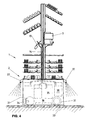
Die Ausschankanlage 1, wie sie in Fig. 1 dargestellt ist, umfasst einen
Aufbauteil 2, welcher am unteren Endbereich 3 eines Trägers 4 befestigt
ist. Dieser Aufbauteil 2 setzt sich zusammen aus Ablageflächen 5, die beispielsweise
der Aufnahme von Ess- und Trinkgeschirr dienen, sowie Stellflächen
6, auf welchen Geräte angeordnet werden können, beispielsweise eine
Kaffeemaschine 7, und Arbeitsflächen 8, die beispielsweise zur Zubereitung
von Speisen oder zur Ausführung von anderen Arbeiten vorgesehen sind. The dispensing system 1, as shown in Fig. 1, comprises one
Der obere Endbereich 9 des Trägers 4 ist an einem Wagen 10 befestigt,
der entlang einer einen Fahrweg bildenden Führungsschiene 11 verfahrbar
ist, wie später noch beschrieben wird. Diese Führungsschiene 11 ist beispielsweise
an einer Decke eines Raumes befestigt, welcher beispielsweise
eine Gaststätte oder eine Kantine bildet. Unterhalb dieser Decke kann eine
Sichtdecke 12 aufgehängt sein, die im Bereich des Verfahrweges des Trägers 4
einen Spalt aufweist, wodurch die Führungsschiene 11 beispielsweise durch
einen Gast, der sich im Raum befindet, nicht sichtbar ist.The upper end region 9 of the
Oberhalb der Arbeitsfläche 8 des Aufbauteils 2 der Ausschankanlage
1 können Auslasshähne 13 für Getränke angeordnet sein. Diese Auslasshähne
13 sind im hier dargestellten Ausführungsbeispiel über Leitungen 14 mit einer
Zentralstelle 40 (Fig. 5) verbunden. Hierzu sind die Leitungen 14 entlang des
Trägers 4 bis in den Bereich des Wagens 10 geführt, wonach diese, Schlaufen
16 bildend, entlang der Führungsschiene 11 bis zur Zentralstelle geführt sind.
Jede Schlaufe 16 der Leitungen 14 ist an einem längs der Führungsschiene 11
verfahrbaren Aufhängeelement 17 gehalten, so dass die Auslasshähne 13 der
Ausschankanlage 1 über die Leitungen 14 dauernd mit der Zentralstelle verbunden
sind, und die Schlaufen 16 beim Verfahren der Ausschankanlage 1
entlang der Führungsschienen 11 enger zusammengeschoben oder auseinander
gezogen werden können.Above the
In gleicher Weise können noch weitere Leitungen von der zentralen Stelle zur Ausschankanlage 1 geführt werden, beispielsweise Frischwasserzufuhrleitungen oder eine Abwasserleitung, insbesondere wenn auf der Ausschankanlage 1 beispielsweise noch ein Waschbecken angeordnet ist, wobei das Abwasser durch die Abwasserleitung mittels einer Pumpe abgeführt werden müsste.In the same way, other lines from the central Be led to the dispensing system 1, for example fresh water supply lines or a sewage pipe, especially if on the bar system 1, for example, a sink is also arranged, wherein the waste water is discharged through the waste water pipe by means of a pump should.
Im Bereich des Trägers 4 sind die Leitungen 14 durch eine Abdekkung
18, die den Träger 4 vollständig umgibt, verdeckt.In the area of the
Selbstverständlich ist es bei der hier dargestellten Ausschankanlage
1 auch denkbar, dass die Ablageflächen 5 als Ablagefächer ausgeführt sind, die
beispielsweise durch Türchen verschliessbar sind, wodurch die darin enthaltenen
Gegenstände vor Staub und gegebenenfalls auch vor neugierigen Blicken
geschützt sind.Of course it is with the bar system shown here
1 also conceivable that the
In Fig. 2 ist im Querschnitt die Führungsschiene 11 dargestellt, die
an der Decke 19 des entsprechenden Raumes, in welchem die Ausschankanlage
verschoben werden soll, aufgehängt ist. Der schematisch dargestellte Wagen
10 ist mit Führungsrollen 20 ausgestattet, die in bekannter, nicht dargestellter
Weise im Wagen 10 um eine fixe Achse drehbar gelagert sind. Die Führungsrollen
20 rollen auf entsprechend auf der Führungsschiene 11 vorgesehenen
Führungsflächen 21 ab. Durch diese Anordnung kann die Ausschankanlage
in keiner Richtung bezüglich der Führungsschiene verkippt werden.In Fig. 2, the
Längs der Führungsschiene 11 sind zwei einander gegenüberliegende
elektrische Leitungen 22 in bekannter Weise eingesetzt. Je ein Stromabnehmer
23, welcher jeweils im Wagen 10 angeordnet sind, steht dauernd im
Kontakt mit der entsprechenden elektrischen Leitung 22, wodurch die Ausschankanlage
1 in bekannter Weise mit Stromanschlüssen für die elektrischen
Geräte ausgestattet werden kann.Along the
Am unteren Ende ist die Führungsschiene 11 mit zwei weiteren Laufflächen
24 ausgestattet, entlang welcher die Hängeelemente 17 verfahrbar
sind, die die Leitungen 14, welche Schlaufen 16 bilden, tragen.At the lower end is the
Am Wagen 10 ist der Träger 4 befestigt, der durch eine entsprechende
Ausnehmung 25 der unterhalb der Decke 19 aufgehängten Sichtdecke
26 hindurch ragt. Entlang dieses Trägers 4 sind die Leitungen 14 geführt, die
beispielsweise zu den Auslasshähnen 13 (Fig. 1) der Ausschankanlage 1 führen.The
Um das Verfahren der Ausschankanlage 1 entlang der Führungsschienen
11 für die Bedienerperson erleichtern zu können, kann vorgesehen
sein, dass mindestens eine der Führungsrollen 20 mit einem Antriebsmotor 27
antreibbar ausgebildet ist. Es wäre auch denkbar, diesen Antriebsmotor 27 in
bekannter Weise über eine Fernbedienung betätigen zu können, so dass die
Ausschankanlage 1 selbsttätig von einem Ort entlang der Führungsschiene 11
zu einem anderen verfahren könnte.To move the bar system 1 along the
Aus der Draufsicht gemäss Fig. 3 auf die Ausschankanlage 1, die
zum Teil im Schnitt dargestellt ist, kann entnommen werden, dass der Träger 4
aus einem I-Profil gebildet ist. Zwischen den beiden Schenkeln 28 und 29 des
Trägers 4 können die Leitungen 14 geführt werden, der Träger 4 ist mit einer
Abdeckung 18 versehen, die ihn vollständig umgibt. Die entsprechenden Leitungen
14 münden in den Auslasshähnen 13 bzw. als Frischwasserzufuhr in
der Kaffeemaschine 7. Des weiteren ist aus dieser Figur die Führungsschiene
11 (teilweise) ersichtlich, sowie die entlang der Führungsschiene 11 geführten
Leitungen 14, wobei eines der Hängeelemente 17 schematisch dargestellt ist.
Auf dem Aufbauteil 2 der Ausschankanlage 1 sind die Arbeitsflächen 8 ersichtlich
sowie auf dem Aufbauteil 2 angeordnete Geräte (Kaffeemaschine 7, Abrechnungscomputer
30).From the top view according to FIG. 3 on the dispensing system 1, the
is shown in part in section, it can be seen that the carrier 4th
is formed from an I-profile. Between the two
Fig. 4 zeigt eine andere Ausführungsvariante einer erfindungsgemässen
Ausschankanlage 1. Der Aufbauteil 2 dieser Ausschankanlage ist mit Rädern
31 versehen, die auf dem Boden 32 abrollen. Im Aufbauteil 2 können Behälter
35 untergebracht sein, die die Getränke enthalten. Jeder Behälter 35 ist
über eine Leitung mit einem Auslasshahn 13 verbunden. Des weiteren sind
wiederum Ablageflächen, Stellflächen für Geräte, beispielsweise eine Kaffeemaschine
7 und Arbeitsflächen vorgesehen.4 shows another embodiment variant of an inventive one
Dispensing system 1. The
Wie bereits erwähnt, wird der Fahrweg durch den Boden 32 gebildet.
Mindestens eines der Räder 31 ist lenkbar, wobei vorgesehen sein kann, dass
diese verfahrbare Ausschankanlage 1 in bekannter Weise automatisch entlang
im Boden 32 verlegter Induktionsschleifen 33 folgt. Hierzu ist das mindestens
eine lenkbare Rad 31 mit Steuermitteln 34 zur Lenkung ausgestattet, die mit
einem nicht dargestellten, mit den Induktionsschleifen zusammenwirkenden
Sensor ausgerüstet ist.As already mentioned, the track is formed by the floor 32.
At least one of the
Die Stromversorgung der auf dieser Ausschankanlage 1 angeordneten
elektrischen Geräte kann über die im Boden verlegten Induktionsschleifen
33 und eine im Aufbauteil 2 angeordnete Sekundärspule 36 in bekannter
Weise erreicht werden.The power supply arranged on this dispensing system 1
electrical devices can via the induction loops laid in the
Dieses Ausführungsbeispiel einer verfahrbaren Ausschankanlage ist insbesondere für Gaststätten oder dergleichen geeignet, bei welchen noch Gäste bedient werden müssen, die sich ausserhalb von Räumlichkeiten befinden, beispielsweise im Garten.This embodiment of a movable bar system is especially suitable for restaurants or the like, where guests are still must be operated that are outside of premises, for example in the garden.
In diesem Ausführungsbeispiel sind die Getränkebehälter 35 in der
Ausschankanlage untergebracht. Dadurch sind Leitungsführungen zu einer
Zentralstelle, wie dies im vorhergehenden Ausführungsbeispiel beschrieben
worden ist, nicht erforderlich.In this embodiment, the
Selbstverständlich ist es auch denkbar, diese am Boden verfahrbare
Ausschankanlage ferngesteuert fahren zu lassen. Hierzu kann eine Antriebseinheit
vorgesehen sein, mit welcher mindestens ein Rad antreibbar ist. Um zu
vermeiden, dass diese Ausschankanlage mit Personen kollidiert, können in
Fahrrichtung Sensoren 37 angebracht sein, die beim Feststellen eines Hindernisses
ein Stoppen der Fahrt bewirken.Of course, it is also conceivable to move these on the floor
Let the dispensing system run remotely. For this purpose, a drive unit
be provided with which at least one wheel can be driven. In order to
avoid that this dispensing system collides with people
Driving
Selbstverständlich ist es auch denkbar, das vorhergehende Ausführungsbeispiel, das eine Ausschankanlage beschreibt, die hängend entlang Führungsschienen verfahrbar ist, mit darauf angeordneten Getränkebehälter zu versehen. Hierdurch könnte ebenfalls auf die Leitungen zur Zentralstelle, die entlang den Führungsschienen verlaufen, verzichtet werden.Of course, it is also conceivable to use the previous embodiment, which describes a dispensing system hanging along guide rails is movable, with beverage containers arranged thereon Mistake. This could also affect the lines to the central office run along the guide rails, are dispensed with.
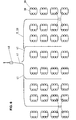
Fig. 5 zeigt in schematischer Darstellung die Anordnung von Tischen
38 und Stühlen 39 beispielsweise in einer Gaststätte oder in einer Kantine. Mit
dem Bezugszeichen 40 ist der Fahrweg, der als Führungsschiene 11 (Fig. 1)
oder als Induktionsspule 33 (Fig. 4) ausgebildet sein kann, bezeichnet. Die
Ausschankanlage 1 lässt sich entlang dieses Fahrweges zwischen die Tische
bewegen. Hierbei kann die Ausschankanlage 1 gemäss dem ersten Ausführungsbeispiel
über Leitungen mit einer Zentralstelle 40 verbunden sein, in welcher
die Behälter für Getränke angeordnet sind. Fig. 5 shows a schematic representation of the arrangement of tables
38 and chairs 39, for example in a restaurant or in a canteen. With
the
Um zwischen verschiedene Reihen von Tischen 38 gelangen zu
können, kann beispielsweise die Führungsschiene 11 mit Weichen 41 versehen
sein.To get between different rows of tables 38
can, for example, provide the
Je nach Grösse des Raumes und der Anzahl von Tischen kann eine
zweite Zentralstelle 40 vorgesehen sein, von welcher aus eine weitere entlang
des Fahrweges verfahrbare Ausschankanlage 1 versorgt werden kann.Depending on the size of the room and the number of tables, one can
second
In Fig. 6 sind wiederum Tische 38 und Stühle 39 dargestellt, die durch die Ausschankanlage 1 bedient werden können. Hierbei kann die Zentralstelle 40 beispielsweise in der Küche angeordnet sein, so dass die Ausschankanlage 1 bis in die Küche verfahren werden kann, wodurch beispielsweise schmutziges Geschirr von der Ausschankanlage direkt in der Küche in die Abwaschmaschinen gebracht werden kann, wonach die Ausschankanlage wieder mit sauberem Geschirr bestückt werden kann.In Fig. 6 tables 38 and chairs 39 are again shown can be served by the dispensing system 1. The central office can do this 40 can be arranged in the kitchen, for example, so that the dispensing system 1 can be moved to the kitchen, for example dirty dishes from the bar in the kitchen the washing machines can be brought, after which the dispensing system can be equipped with clean dishes again.
Die erfindungsgemässe Ausschankanlage kann jeweils den Bedürfnissen entsprechend ausgebaut und mit den erforderlichen Geräten versehen sein. Dadurch wird die Effizienz eines Bedienvorganges für einen Gast beispielsweise in einer Gaststätte oder in einer Kantine optimal gesteigert. Mit derartigen erfindungsgemässen Ausschankanlage werden die Wege, die üblicherweise das Bedienerpersonal bei der Ausübung ihrer Tätigkeit zurücklegt, massiv reduziert, weil die Ausschankanlage zum zu bedienenden Gast "mitgenommen" werden kann. Die Tätigkeit wird massiv erleichtert. Gegebenenfalls mit derartigen erfindungsgemässen Ausschankanlagen Personal eingespart werden, ohne dass die Effizienz der Bedienung darunter leidet.The dispensing system according to the invention can meet the needs expanded accordingly and provided with the necessary equipment his. This makes the efficiency of an operating procedure for a guest, for example optimally increased in a restaurant or in a canteen. With such Dispensing system according to the invention are the routes that are usually the operator travels massively when performing their duties reduced because the bar system "brought" to the guest to be served can be. The activity is massively facilitated. If necessary with personnel of such dispensing systems according to the invention are saved, without affecting the efficiency of the operation.
Claims (13)
Priority Applications (1)
| Application Number | Priority Date | Filing Date | Title |
|---|---|---|---|
| EP98810784A EP0980663A1 (en) | 1998-08-14 | 1998-08-14 | Beverage dispensing device,especially for catering purpose |
Applications Claiming Priority (1)
| Application Number | Priority Date | Filing Date | Title |
|---|---|---|---|
| EP98810784A EP0980663A1 (en) | 1998-08-14 | 1998-08-14 | Beverage dispensing device,especially for catering purpose |
Publications (1)
| Publication Number | Publication Date |
|---|---|
| EP0980663A1 true EP0980663A1 (en) | 2000-02-23 |
Family
ID=8236253
Family Applications (1)
| Application Number | Title | Priority Date | Filing Date |
|---|---|---|---|
| EP98810784A Withdrawn EP0980663A1 (en) | 1998-08-14 | 1998-08-14 | Beverage dispensing device,especially for catering purpose |
Country Status (1)
| Country | Link |
|---|---|
| EP (1) | EP0980663A1 (en) |
Cited By (1)
| Publication number | Priority date | Publication date | Assignee | Title |
|---|---|---|---|---|
| CN104444014A (en) * | 2014-10-11 | 2015-03-25 | 陕西科技大学 | Automated vegetable distribution device based on PLC |
Citations (6)
| Publication number | Priority date | Publication date | Assignee | Title |
|---|---|---|---|---|
| US1442211A (en) * | 1919-07-05 | 1923-01-16 | John M Baitinger | Method of feeding people |
| US3464363A (en) * | 1967-11-20 | 1969-09-02 | Randell J Wishart | Automatic food delivery and return system |
| US4190134A (en) * | 1977-04-14 | 1980-02-26 | Noboru Kato | Dish carrying system |
| CH619901A5 (en) * | 1977-04-19 | 1980-10-31 | Von Roll Ag | Method and device for providing people with meals |
| FR2473473A1 (en) * | 1980-01-15 | 1981-07-17 | Brami Marc | Manual cold drink dispenser - has insulated container with delivery pipe and integral valve carried in harness with plastics beakers and money pouch |
| FR2564815A1 (en) * | 1984-05-24 | 1985-11-29 | Vautier Lacroix Sa | Independent trolley for dispensing hot beverages |
-
1998
- 1998-08-14 EP EP98810784A patent/EP0980663A1/en not_active Withdrawn
Patent Citations (6)
| Publication number | Priority date | Publication date | Assignee | Title |
|---|---|---|---|---|
| US1442211A (en) * | 1919-07-05 | 1923-01-16 | John M Baitinger | Method of feeding people |
| US3464363A (en) * | 1967-11-20 | 1969-09-02 | Randell J Wishart | Automatic food delivery and return system |
| US4190134A (en) * | 1977-04-14 | 1980-02-26 | Noboru Kato | Dish carrying system |
| CH619901A5 (en) * | 1977-04-19 | 1980-10-31 | Von Roll Ag | Method and device for providing people with meals |
| FR2473473A1 (en) * | 1980-01-15 | 1981-07-17 | Brami Marc | Manual cold drink dispenser - has insulated container with delivery pipe and integral valve carried in harness with plastics beakers and money pouch |
| FR2564815A1 (en) * | 1984-05-24 | 1985-11-29 | Vautier Lacroix Sa | Independent trolley for dispensing hot beverages |
Cited By (2)
| Publication number | Priority date | Publication date | Assignee | Title |
|---|---|---|---|---|
| CN104444014A (en) * | 2014-10-11 | 2015-03-25 | 陕西科技大学 | Automated vegetable distribution device based on PLC |
| CN104444014B (en) * | 2014-10-11 | 2016-05-04 | 陕西科技大学 | A kind of garnishes of the automation based on PLC device |
Similar Documents
| Publication | Publication Date | Title |
|---|---|---|
| DE60030582T2 (en) | DEVICE AND METHOD FOR A WASHING SYSTEM | |
| DE4033373C2 (en) | Trolley | |
| DE2621021A1 (en) | SYSTEM AND EQUIPMENT FOR THE AUTOMATIC HANDLING OF HAND TROLLEYS, IN PARTICULAR HOSPITAL TROLLEYS | |
| DE2807002C2 (en) | Pallet rack warehouse | |
| AT389690B (en) | SHELVING PRODUCTS | |
| WO1997037564A1 (en) | Safety device for a storage device | |
| DE1187943B (en) | Automatic car wash | |
| DE2425728A1 (en) | DRIVING AUTOMATIC OR ROBOT | |
| EP0980663A1 (en) | Beverage dispensing device,especially for catering purpose | |
| EP0316273B1 (en) | Conveyor system | |
| DE839476C (en) | Device for conveying items arranged in rows, especially containers for files, index cards or the like. | |
| DE2100854A1 (en) | Conveying device with a rail-guided vehicle or vehicle | |
| DE4208438A1 (en) | Passenger service supply for aircraft on long journeys - has catering container in under floor area with freight loading system beneath work cabin area | |
| EP0298341A1 (en) | Handling apparatus for storage racks | |
| DE4021021C2 (en) | Transport vehicle for the transportation of people with sales car | |
| DE19708389C2 (en) | Track switch for a track-bound floor conveyor system | |
| DE2942839A1 (en) | Automatically guided load handling vehicle with electric drive - has current rail running along overhead guidance track | |
| EP3609816B1 (en) | High-bay warehouse for storing items in storage locations of bays | |
| DE3513068A1 (en) | Mobile undercarriage with castors | |
| DE3707395C1 (en) | Return system for rail-bound transport trucks without self-propulsion | |
| DE19911864A1 (en) | Automatic watering and chemical treatment system for bedding plants | |
| DE3707295C1 (en) | Suspension rail conveyor system | |
| DE3320434A1 (en) | Process and apparatus for the optional, ordered storage of objects, in particular garments | |
| DE3737750C1 (en) | Switch arrangement | |
| DE2654194C2 (en) | Mobile shelving system |
Legal Events
| Date | Code | Title | Description |
|---|---|---|---|
| PUAI | Public reference made under article 153(3) epc to a published international application that has entered the european phase |
Free format text: ORIGINAL CODE: 0009012 |
|
| AK | Designated contracting states |
Kind code of ref document: A1 Designated state(s): AT BE CH CY DE DK ES FI FR GB GR IE IT LI LU MC NL PT SE |
|
| AX | Request for extension of the european patent |
Free format text: AL;LT;LV;MK;RO;SI |
|
| AKX | Designation fees paid | ||
| STAA | Information on the status of an ep patent application or granted ep patent |
Free format text: STATUS: THE APPLICATION IS DEEMED TO BE WITHDRAWN |
|
| 18D | Application deemed to be withdrawn |
Effective date: 20000824 |