EP0979985A2 - Vorrichtung zur Wärmebehandlung einer Warenbahn - Google Patents
Vorrichtung zur Wärmebehandlung einer Warenbahn Download PDFInfo
- Publication number
- EP0979985A2 EP0979985A2 EP99115983A EP99115983A EP0979985A2 EP 0979985 A2 EP0979985 A2 EP 0979985A2 EP 99115983 A EP99115983 A EP 99115983A EP 99115983 A EP99115983 A EP 99115983A EP 0979985 A2 EP0979985 A2 EP 0979985A2
- Authority
- EP
- European Patent Office
- Prior art keywords
- nozzles
- nozzle
- web
- jet
- jets
- Prior art date
- Legal status (The legal status is an assumption and is not a legal conclusion. Google has not performed a legal analysis and makes no representation as to the accuracy of the status listed.)
- Granted
Links
Images


Classifications
-
- F—MECHANICAL ENGINEERING; LIGHTING; HEATING; WEAPONS; BLASTING
- F26—DRYING
- F26B—DRYING SOLID MATERIALS OR OBJECTS BY REMOVING LIQUID THEREFROM
- F26B21/00—Arrangements for supplying or controlling air or other gases for drying solid materials or objects
- F26B21/50—Ducting arrangements from the source of air or other gases to the materials or objects being dried
-
- F—MECHANICAL ENGINEERING; LIGHTING; HEATING; WEAPONS; BLASTING
- F26—DRYING
- F26B—DRYING SOLID MATERIALS OR OBJECTS BY REMOVING LIQUID THEREFROM
- F26B13/00—Machines and apparatus for drying fabrics, fibres, yarns, or other materials in long lengths, with progressive movement
- F26B13/10—Arrangements for feeding, heating or supporting materials; Controlling movement, tension or position of materials
Definitions
- the invention relates to a device for heat treatment a web with above and below one nozzle boxes arranged in the middle web transport level, each nozzle box one of the web facing nozzle bottom with a variety of nozzles having.
- the webs are usually on their longitudinal edges held by means of tension and transport chains and transported through the device.
- the web will with width addition and if necessary lead in length in the stenter retracted.
- the web of goods therefore hangs in the beginning until the heat treatment turns into a progressive shrinkage that gradually leads to the Excess area consumes, so that at the machine outlet a flat web with the required dimensions is available stands.
- the web also in the area of the first treatment zones of the device if possible in the area of a middle goods web transport level is held by the connection level is formed between the tension chains.
- the invention is therefore based on the object Device for the heat treatment of a web according to to further develop the preamble of claim 1, that heat treatment as uniform as possible reached the web with the lowest possible pressure loss can be.
- jets for jet bathing slanted there are at least some jets for jet bathing slanted.
- the nozzles themselves point a cylindrical part that is oblique to the bottom of the nozzle is aligned, with the cylindrical part on its has one end of a nozzle mouth and at its at the other end a funnel-shaped, curved one Connects area that merges into the nozzle bottom.
- the nozzles are in wells of the just formed Nozzle bottom provided.
- the web can be so treat with treatment gas that the web both lengthways and crossways to the direction of transport spreads out in wave form.
- the nozzles of the top and lower nozzle boxes are preferably one another aligned that around the middle Goods web transport level alternately bulges after surrender below and above.
- the web of goods shows up to the viewer as "three-dimensional Mountain landscape ".
- the Cover elements a reliable cover of not enable required nozzles. This can be done in particular then reliably realize when the nozzle bottom is just trained.
- the cover elements can both inside and outside the nozzle box to be ordered.
- the web 2 is spread over a wide range during this heat treatment Condition continuous through the device 1 transported through.
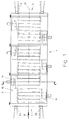
- the device 1 contains a machine housing in the usual way 3, in its longitudinal direction in several Treatment zones can be divided and at his one end a web inlet 4 and at its other End of a web run 5 - each in about Form of a transverse slot - has.
- the Material web 2 is thus in during its heat treatment Longitudinally transported through the tensioner 1.
- the direction of transport is with arrow 6 (Fig.1) marked.
- tensioning or transport chains 7, 8 are provided, those with clamps or needle bars like this are equipped that the web 2 on their two Longitudinal edges 2a, 2b are detected and held can.
- the transverse connection plane between the two Transport chains 7, 8 (in the holding area of the longitudinal edges of the web) is referred to below as the middle goods web transport level 9 designated.
- the middle goods web transport level 9 designated.
- the web 2 In the shown in Fig.2 Embodiment is the web 2 exactly in the middle web transport level 9.
- nozzle devices 10 in the form of inflatable nozzle boxes tempered gases, in particular from warm air to the arranged web side facing them.
- nozzle boxes 10 in the form of inflatable nozzle boxes tempered gases, in particular from warm air to the arranged web side facing them.
- a blower 11 for generation an air circulation and at least one control valve 12 belong to each side of the web a treatment gas in a required, adjustable or controllable amount to be able to supply.
- a separate fan can be assigned, by controlling its speed the corresponding one Air volume can be regulated.
- the location of the web 2 is essentially by the Tension or transport chains 7, 8 and the amount of determined by the inflated gases 10 gases. The following is influencing the situation the web 2 through the nozzle devices considered.
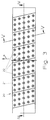
- the nozzles 22 are in rows transverse to the transport direction 6 arranged, the nozzles of a row each have the same distance from each other. In the illustrated 3 are the nozzles of the slightly offset in the transport direction 6 adjacent row arranged to the previous row.
- the lower nozzle box 30 is in a corresponding manner built up.
- Each of the nozzles 22 is in a recess 21a of the nozzle base 21 is formed.
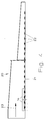
- the nozzle has a cylindrical part 22a, on its one end of a nozzle mouth 22b is formed and itself at the other end a funnel-shaped, curved region 22c connects into the nozzle bottom 21 passes.
- the nozzle mouth 22b is opposite to that just formed nozzle bottom 21 into the recess 21a arranged withdrawn so that, if necessary, on the nozzle bottom 21st adjacent material webs not in contact with the nozzle mouth can come and be damaged.
- the peculiarity of the nozzle 22 is that it is aligned obliquely to the nozzle bottom 21.
- the alignment the nozzle is made by the orientation of the cylindrical Determines part 22a, whose central axis 22d with the nozzle base 21 encloses an angle ⁇ ⁇ 90 °.
- the special effects associated with such a nozzle with regard to the web 2 can be achieved illustrated in more detail with reference to FIGS. 8 to 23.
- nozzle 22 shown in Figure 6 is in the Drawing shown upper edge of the curved area 22c in a plane 22e that is parallel to the nozzle mouth 22b and aligned parallel to the nozzle base 21 is.
- the central axis 22d of the cylindrical part 22a is therefore not perpendicular to the plane 22e or plane formed by the nozzle mouth 22b.
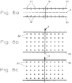
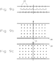
- FIGS Various exemplary embodiments are now shown in FIGS shown how the nozzles of the top and bottom Nozzle boxes can be aligned and which Effects arise.
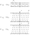
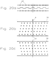
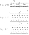
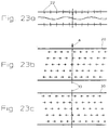
- the view shows a each a very schematic side view of the upper and lower nozzle boxes 20, 30 with the one in between aligned web 2.
- the nozzles 22 and 32 and in particular their orientation are in this View shown with the help of arrows.
- FIG. 8b shows the nozzle bottom of the upper nozzle box 20, while in Fig.8c the bottom of the lower nozzle box 30 is illustrated.
- the nozzles 22 and 32 are represented by simple circles, the alignment of the nozzles by small flags is indicated.
- the longitudinal median plane is also in all three views 13 of the web 2 shown.
- the design of the Nozzles in the exemplary embodiments explained in more detail below is not on the variant shown in Fig.6 limited.
- nozzles can also be used 22 'according to FIG. 7 or completely different nozzles are used, at least some of the nozzles of a nozzle box aligned obliquely to its nozzle bottom are.
- the nozzle arrangement according to FIG. 9 essentially corresponds of the nozzle arrangement according to FIG. 8.
- the in the direction of transport 6 aligned nozzles of the upper nozzle box 20 are only half a hole pitch shifted transversely to the transport direction. This will make the Material web across the direction of transport in a light Wavy line offset what the quality of the goods from The advantage is (see Fig.9a).
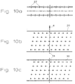
- the arrangement of the nozzles according to that shown in Fig.10 The embodiment again corresponds to the embodiment 8 with the difference that the Nozzle holes in the neighboring 6 in the transport direction Row of nozzles arranged offset from the previous row are. This arrangement is especially for more even drying on more sensitive webs advantageous.
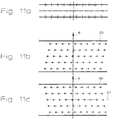
- FIG. 11 differs from of the nozzle arrangement according to FIG. 10 only in that the nozzles of the upper nozzle box as a mirror image the nozzles of the lower nozzle box are arranged, wherein the middle row of nozzles in the direction of transport 6 Mirror axis 24 forms.
- the nozzle arrangement according to FIG. 12 corresponds to the arrangement 10, but with the nozzles of the upper Nozzle box 20 by half a hole division across Transport direction 6 opposite the nozzles of the lower nozzle box 30 are shifted.
- nozzles according to Fig. 13 are according to the embodiment arranged according to Fig.11, the nozzles the upper nozzle box 20 by half a hole pitch are moved transversely to the transport direction 6.
- the nozzles of the upper and lower nozzle box 20, 30 both in and also in alignment with one another transversely to the direction of transport 6 arranged.
- the cross to the direction of transport of the web side-by-side nozzles are alternating facing and away from each other.
- the nozzles in the direction of transport each have the same orientation. With Such an arrangement creates a wavy exposure the textile web.
- nozzles according to Fig. 14 are in the transport direction neighboring row slightly offset from the previous one Row arranged.
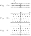
- the nozzle arrangement corresponds to the upper nozzle box 20 of the nozzle arrangement of the upper nozzle box according to Fig.15b.
- the nozzles of the lower nozzle box 30 according to FIG. 16c are mirrored around the middle row of nozzles arranged.
- 17 corresponds to the nozzle arrangement 15, wherein the nozzles of the lower nozzle box 30 are arranged identically and the nozzles the upper nozzle box by a hole division across Transport direction 6 are shifted, this creates a wavy load on the textile web.
- Fig. 18a are four nozzles each of the upper and lower nozzle boxes inclined towards each other. This creates a "hilly" loading of the textile web.
- the facing each other and away from each other Nozzles are in the upper and lower nozzle boxes 20, 30 congruent.
- the nozzle arrangement according to FIG. 19 corresponds to the nozzle arrangement according to FIG. 18, but the nozzles directed towards and away from each other are displaced by a hole division in the transport direction 6 and transversely to the transport direction in the upper nozzle box 20. This increases the “undulating " loading of the textile web.
- nozzles shown in Fig. 20 are mirror images arranged to the nozzles according to Fig.18, whereby a little other "hilly" loading of the textile web is achieved.
- nozzles in Fig. 22 are inclined so that of the transversely to the direction of transport of the web next to each other arranged nozzles alternately two in each one and two nozzles aligned in the other direction are. This in turn creates a wavy one Loading of the textile web, the shaft spacing however, are larger than in the embodiment according to Fig. 17.
- nozzles of the lower nozzle box are arranged in mirror image.
- this offers Interplay of diagonally aligned to the nozzle bottom Nozzles various ways to close the web act upon. Especially in the area of the first treatment zones the device becomes a wavy exposure prefer the web, while at the web outlet, where the shrinkage of the weft threads already has expired, aligns the nozzles so that the Goods web essentially in the middle web transport level is held.
- material webs often have to be different Wide heat treated so that the tension chains, with which the material webs on their longitudinal edges be held sideways to adapt to the respective Width of the material web across the direction of transport are adjustable.
- the nozzle system is for the largest occurring width of the web is designed. During treatment of webs whose width is smaller than that maximum working width to be processed must be special Measures are taken to keep the air out that part of the nozzle system that does not have a web faces, not unused on the web flows past.
- Cover elements 14 provided to the effective air passage area to the width of the respective Adjust web.
- the cover elements can from a single slider or from several individual ones Cover elements exist, which are suitable for Controlled change in the effective air passage area become.
- the cover elements are expediently inside the nozzle boxes arranged, but can also outside of the nozzle box in the area of the nozzle base be like that in Fig. 4 with dashed lines is indicated. Due to the flat design of the nozzle base 21 can be done in a particularly simple manner reliable coverage of the nozzles not required realize. With an external attachment of the cover elements these are directly on the nozzle bottom 21 guided. When attaching the cover elements 14 in Inside the nozzle boxes, these come with the curved ones Areas 22c of the nozzles 22 in contact. But here too lies the upper edge of all curved areas of the nozzles 22 on a common level and thereby ensure reliable coverage of those not required Nozzles.
Landscapes
- Engineering & Computer Science (AREA)
- Mechanical Engineering (AREA)
- General Engineering & Computer Science (AREA)
- Textile Engineering (AREA)
- Treatment Of Fiber Materials (AREA)
- Tunnel Furnaces (AREA)
Abstract
Description
- Fig.1
- eine schematische Aufsicht einer Vorrichtung zur Wärmebehandlung einer Warenbahn,
- Fig.2
- eine schematische Seitenansicht der Vorrichtung gemäß Fig.1,
- Fig.3
- eine Ansicht des Düsenbodens eines Düsenkastens,
- Fig.4
- eine Schnittdarstellung längs der Linie IV-IV der Fig.3,
- Fig.5
- eine Schnittdarstellung längs der Linie V-V der Fig.3,
- Fig.6 und 7
- Schnittdarstellungen von Düsen gemäß weiteren Ausführungsbeispielen,
- Fig.8 bis 23
- schematische Darstellungen von verschiedenen Ausführungsbeispielen hinsichtlich der Ausrichtung der einzelnen Düsen der oberen und unteren Düsenkästen.
Claims (15)
- Vorrichtung zur Wärmebehandlung einer Warenbahn (2) mit oberhalb und unterhalb einer mittleren Warenbahn-Transportebene (9) angeordneten Düsenkästen (20, 30), wobei jeder Düsenkasten einen der Warenbahn zugewandten Düsenboden (21) mit einer Vielzahl von Düsen (22, 22') aufweist, wobei zumindest einige Düsen zum Düsenboden schräg ausgerichtet sind,
dadurch gekennzeichnet, daßdie Düsen einen zylindrischen Teil (21a) aufweisen, der schräg zum Düsenboden ausgerichtet ist undder zylindrische Teil (21a) an seinem einen Ende einen Düsenmund (21b) aufweist und sich an seinem anderen Ende ein trichterförmig erweiternder, gekrümmter Bereich (21c) anschließt, der in den Düsenboden (21) übergeht, undder Düsenboden (21) eben und die Düsen (22, 22') in Vertiefungen (21a) des Düsenbodens ausgebildet sind. - Vorrichtung nach Anspruch 1, dadurch gekennzeichnet, daß alle Düsen zum Düsenboden schräg ausgerichtet sind.
- Vorrichtung nach einem der vorhergehenden Ansprüche, dadurch gekennzeichnet, daß die Düsen der oberen und unteren Düsenkästen (20, 30) derart zueinander ausgerichtet sind, daß sich an der Warenbahn (2) um die mittlere Warenbahntransportebene (9) abwechselnd Ausbeulungen nach oben und unten ergeben.
- Vorrichtung nach einem der vorhergehenden Ansprüche, dadurch gekennzeichnet, daß die Düsen der oberen und unteren Düsenkästen (20, 30) derart zueinander ausgerichtet sind, daß sich an der Warenbahn (2) um die mittlere Warenbahntransportebene (9) abwechselnd Ausbeulungen nach oben und unten ergeben, wobei sich die Ausbeulungen sowohl längs als auch quer zur Transportrichtung ausbilden.
- Vorrichtung nach Anspruch 1, dadurch gekennzeichnet, daß jeweils vier Düsen zueinander geneigt sind.
- Vorrichtung nach Anspruch 1, dadurch gekennzeichnet, daß die rechts bzw. links der Längsmittelebene (13) der Warenbahn (2) und oberhalb bzw. unterhalb der Warenbahn angeordneten Düsen gegenüber dem Düsenboden zur Längsmittelebene der Warenbahn geneigt ausgerichtet sind.
- Vorrichtung nach Anspruch 1, dadurch gekennzeichnet, daß die quer zur Transportrichtung (6) der Warenbahn (2) nebeneinander angeordneten Düsen abwechselnd zu- und voneinander weg gerichtet sind.
- Vorrichtung nach Anspruch 1, dadurch gekennzeichnet, daß von den quer zur Transportrichtung (6) der Warenbahn (2) nebeneinander angeordneten Düsen abwechselnd jeweils wenigstens zwei Düsen in der einen und die gleiche Anzahl von Düsen in der anderen Richtung ausgerichtet sind.
- Vorrichtung nach einem der vorhergehenden Ansprüche, dadurch gekennzeichnet, daß die Düsen der oberen und unteren Düsenkästen (20, 30) derart zueinander ausgerichtet sind, daß sich die Warenbahn (2) quer zur Transportrichtung (6) in Wellenform ausbreitet.
- Vorrichtung nach einem der vorhergehenden Ansprüche, dadurch gekennzeichnet, daß die Düsen der oberen und unteren Düsenkästen (20, 30) deckungsgleich zueinander liegen.
- Vorrichtung nach einem der vorhergehenden Ansprüche, dadurch gekennzeichnet, daß die Düsen der oberen und unteren Düsenkästen (20, 30) versetzt zueinander liegen.
- Vorrichtung nach einem der vorhergehenden Ansprüche, dadurch gekennzeichnet, daß die Düsen quer zur Transportrichtung (6) in Reihen angeordnet sind, wobei die Düsen der in Transportrichtung benachbarten Reihe versetzt zur vorangegangenen Reihe angeordnet sind.
- Vorrichtung nach einem der vorhergehenden Ansprüche, dadurch gekennzeichnet, daß zur Anpassung der wirksamen Luftdurchtrittsfläche des Düsenbodens (21) an die Breite der jeweiligen Warenbahn (2) Abdeckelemente (14) vorgesehen sind.
- Vorrichtung nach Anspruch 14, dadurch gekennzeichnet, daß die Abdeckelemente (15) als Schieber ausgebildet und innerhalb der Düsenkästen angeordnet sind.
- Vorrichtung nach Anspruch 1, dadurch gekennzeichnet, daß der Düsenboden (21) eben ausgestaltet ist und die Düsen (22) einen Düsenmund (22b) aufweisen, der in der Ebene des Düsenbodens (21) liegt.
Applications Claiming Priority (2)
| Application Number | Priority Date | Filing Date | Title |
|---|---|---|---|
| DE19836834A DE19836834A1 (de) | 1998-08-13 | 1998-08-13 | Vorrichtung zur Wärmebehandlung einer Warenbahn |
| DE19836834 | 1998-08-13 |
Publications (3)
| Publication Number | Publication Date |
|---|---|
| EP0979985A2 true EP0979985A2 (de) | 2000-02-16 |
| EP0979985A3 EP0979985A3 (de) | 2001-03-14 |
| EP0979985B1 EP0979985B1 (de) | 2002-02-06 |
Family
ID=7877501
Family Applications (1)
| Application Number | Title | Priority Date | Filing Date |
|---|---|---|---|
| EP99115983A Expired - Lifetime EP0979985B1 (de) | 1998-08-13 | 1999-08-13 | Vorrichtung zur Wärmebehandlung einer textilen Warenbahn |
Country Status (5)
| Country | Link |
|---|---|
| EP (1) | EP0979985B1 (de) |
| AT (1) | ATE213061T1 (de) |
| DE (2) | DE19836834A1 (de) |
| ES (1) | ES2168826T3 (de) |
| PT (1) | PT979985E (de) |
Cited By (7)
| Publication number | Priority date | Publication date | Assignee | Title |
|---|---|---|---|---|
| EP1291458A3 (de) * | 2001-09-07 | 2004-09-29 | Hirano Tecseed Co., Ltd. | Vorrichtung zur Wärmebehandlung von Warenbahnen |
| GB2384295B (en) * | 2001-12-12 | 2006-07-12 | Falmer Investment Ltd | Improvements in and relating to Processing fabric |
| WO2009141841A1 (en) * | 2008-05-19 | 2009-11-26 | Coramtex S.R.L. | Machine for the processing of open - width fabrics and related method |
| WO2011123083A1 (en) * | 2010-03-29 | 2011-10-06 | Lafer Tekstil Makina San. Tic. A.S. | A nozzle system to be used for drying purposes in ram machines |
| WO2015173835A1 (en) * | 2014-05-15 | 2015-11-19 | Inspiron Engineering Private Limited | A manifold |
| WO2017164833A1 (en) * | 2016-03-25 | 2017-09-28 | Has Group Makina Endustri A.S. | Nozzle system |
| DE102022100704A1 (de) | 2022-01-13 | 2023-07-13 | Brückner Maschinenbau GmbH & Co. KG | Düsenkasten sowie eine Reckanlage mit einem zugehörigen Düsenkasten |
Citations (3)
| Publication number | Priority date | Publication date | Assignee | Title |
|---|---|---|---|---|
| DE2120805A1 (de) | 1971-04-28 | 1972-11-16 | Fa. A. Monforts, 4050 Mönchengladbach | Vorrichtung zum schwebend Breitführen von Warenbahnen |
| DE2339964A1 (de) | 1973-08-07 | 1975-02-20 | Brueckner Trockentechnik Kg | Duesenanordnung zur schwebenden fuehrung einer warenbahn |
| DE4306584C1 (de) | 1993-03-03 | 1994-07-07 | Langbein & Engelbrecht | Vorrichtung zur schwebenden Führung einer Warenbahn |
Family Cites Families (15)
| Publication number | Priority date | Publication date | Assignee | Title |
|---|---|---|---|---|
| DE1277754B (de) * | 1961-09-14 | 1968-09-12 | Vits G M B H Maschf | Vorrichtung zum beruehrungsfreien Halten einer durch den Zwischenraum zwischen duesenbesetzten Blaskaesten schwebend gefuehrten Gutbahn |
| US3429057A (en) * | 1966-12-05 | 1969-02-25 | Proctor & Schwartz Inc | Dryers |
| DE2935866A1 (de) * | 1978-09-11 | 1980-03-20 | Valmet Oy | Bahntrockner nach dem lufttrageprinzip |
| DE2927974C2 (de) * | 1979-07-11 | 1985-08-08 | Vepa AG, Riehen, Basel | Vorrichtung zur kontinuierlichen Schrumpfbehandlung von Textilbahnen |
| FI60261C (fi) * | 1980-03-28 | 1981-12-10 | Valmet Oy | Oevertrycksmunstycke foer behandling av banor |
| DE3036669A1 (de) * | 1980-09-29 | 1982-05-13 | Babcock Textilmaschinen Kg (Gmbh & Co), 2105 Seevetal | Vorrichtung zum waermebehandeln, insbesondere zum trocknen von textilbahnen |
| US4437612A (en) * | 1981-12-28 | 1984-03-20 | Midland-Ross Corporation | Flotation nozzle |
| DE3410673C2 (de) * | 1984-03-23 | 1986-02-13 | C. Keller GmbH u. Co KG, 4530 Ibbenbüren | Düsenkasten zum Wärmebehandeln von Furnieren in einem Furniertrockner |
| US4551926A (en) * | 1984-05-23 | 1985-11-12 | C. Keller Gmbh U. Co. Kg Maschinenfabrik | Nozzle box for heat treatment of veneering |
| NO890790L (no) * | 1989-02-24 | 1990-08-27 | Severin Severinsen | Fremgangsmaate ved fiksering av en bane, og fikseringsanlegg for fiksering av baner. |
| DE4331496C2 (de) * | 1992-10-07 | 1998-03-19 | Monforts Gmbh & Co A | Ebenes Düsensystem |
| DE4406846C1 (de) * | 1994-03-03 | 1995-05-04 | Koenig & Bauer Ag | Vorrichtung zum Trocknen von bedruckten Bogen oder Bahnen in Druckmaschinen |
| DE4338620A1 (de) * | 1993-11-11 | 1995-05-18 | Monforts Textilmaschinen Gmbh | Vorrichtung zum Beblasen einer textilen Warenbahn |
| DE4406847C2 (de) * | 1994-03-03 | 1997-07-10 | Koenig & Bauer Albert Ag | Vorrichtung zum schwebenden Führen von Bogen oder Bahnen |
| DE19651541A1 (de) * | 1996-12-11 | 1998-06-18 | Brueckner Trockentechnik Gmbh | Spannrahmen |
-
1998
- 1998-08-13 DE DE19836834A patent/DE19836834A1/de not_active Withdrawn
-
1999
- 1999-08-13 EP EP99115983A patent/EP0979985B1/de not_active Expired - Lifetime
- 1999-08-13 DE DE59900818T patent/DE59900818D1/de not_active Expired - Lifetime
- 1999-08-13 AT AT99115983T patent/ATE213061T1/de active
- 1999-08-13 PT PT99115983T patent/PT979985E/pt unknown
- 1999-08-13 ES ES99115983T patent/ES2168826T3/es not_active Expired - Lifetime
Patent Citations (3)
| Publication number | Priority date | Publication date | Assignee | Title |
|---|---|---|---|---|
| DE2120805A1 (de) | 1971-04-28 | 1972-11-16 | Fa. A. Monforts, 4050 Mönchengladbach | Vorrichtung zum schwebend Breitführen von Warenbahnen |
| DE2339964A1 (de) | 1973-08-07 | 1975-02-20 | Brueckner Trockentechnik Kg | Duesenanordnung zur schwebenden fuehrung einer warenbahn |
| DE4306584C1 (de) | 1993-03-03 | 1994-07-07 | Langbein & Engelbrecht | Vorrichtung zur schwebenden Führung einer Warenbahn |
Cited By (9)
| Publication number | Priority date | Publication date | Assignee | Title |
|---|---|---|---|---|
| EP1291458A3 (de) * | 2001-09-07 | 2004-09-29 | Hirano Tecseed Co., Ltd. | Vorrichtung zur Wärmebehandlung von Warenbahnen |
| GB2384295B (en) * | 2001-12-12 | 2006-07-12 | Falmer Investment Ltd | Improvements in and relating to Processing fabric |
| WO2009141841A1 (en) * | 2008-05-19 | 2009-11-26 | Coramtex S.R.L. | Machine for the processing of open - width fabrics and related method |
| WO2011123083A1 (en) * | 2010-03-29 | 2011-10-06 | Lafer Tekstil Makina San. Tic. A.S. | A nozzle system to be used for drying purposes in ram machines |
| WO2015173835A1 (en) * | 2014-05-15 | 2015-11-19 | Inspiron Engineering Private Limited | A manifold |
| WO2017164833A1 (en) * | 2016-03-25 | 2017-09-28 | Has Group Makina Endustri A.S. | Nozzle system |
| DE102022100704A1 (de) | 2022-01-13 | 2023-07-13 | Brückner Maschinenbau GmbH & Co. KG | Düsenkasten sowie eine Reckanlage mit einem zugehörigen Düsenkasten |
| CN116423722A (zh) * | 2022-01-13 | 2023-07-14 | 布鲁克纳机械有限责任两合公司 | 喷嘴箱以及带有所属喷嘴箱的拉伸设备 |
| US12343949B2 (en) | 2022-01-13 | 2025-07-01 | Brückner Maschinenbau GmbH | Nozzle box as well as a stretching unit comprising a corresponding nozzle box |
Also Published As
| Publication number | Publication date |
|---|---|
| ES2168826T3 (es) | 2002-06-16 |
| DE19836834A1 (de) | 2000-03-02 |
| EP0979985A3 (de) | 2001-03-14 |
| PT979985E (pt) | 2002-07-31 |
| DE59900818D1 (de) | 2002-03-21 |
| ATE213061T1 (de) | 2002-02-15 |
| EP0979985B1 (de) | 2002-02-06 |
Similar Documents
| Publication | Publication Date | Title |
|---|---|---|
| DE69211851T2 (de) | Verfahren und vorrichtung zur fortlaufenden behandlung von materialbahnen | |
| DE3036669C2 (de) | ||
| DE3038167C2 (de) | ||
| DE3318861C1 (de) | Vorrichtung zum schwebenden Fuehren von Materialbahnen,insbesondere mit einer Heizeinrichtung zum Gluehen von Aluminiumbaendern | |
| EP0979985B1 (de) | Vorrichtung zur Wärmebehandlung einer textilen Warenbahn | |
| DE3815211C2 (de) | ||
| CH619010A5 (de) | ||
| DE2056889A1 (de) | Behandlungsvorrichtung, insbesondere für die Wärmebehandlung von bahnförmigen Materialien | |
| DE2918833C2 (de) | Vorrichtung zum Trocknen und Krumpfen von textiler Maschenware | |
| DE3007752C2 (de) | Anordnung zur Beaufschlagung von Warenbahnen | |
| CH640012A5 (de) | Verfahren zum ausstossen eines fluid-hilfsstrahls in einem duesenwebstuhl und duesenwebstuhl zur durchfuehrung des verfahrens. | |
| DE3815209C2 (de) | ||
| DE1542417C3 (de) | Düsenanordnung für Trockner oder Wärmebehandlungsanlagen für bahnförmiges Gut | |
| DE3904774C1 (de) | ||
| DE3220076A1 (de) | Luftblaskasten fuer die trockenpartie einer papiermaschine | |
| EP4000863B1 (de) | Behandlungsanlage für eine durch einen behandlungsofen hindurchführbare flexible materialbahn, insbesondere kunststofffolie | |
| EP0753357B1 (de) | Vorrichtung zum Aufbringen eines über die Arbeitsbreite gleichmässig dünnen Flüssigkeitsfilmes auf eine Warenbahn | |
| DE970793C (de) | Vorrichtung zum Trocknen von Gewebe- oder anderen Stoffbahnen | |
| DE19536352C2 (de) | Vorrichtung zum Führen und Behandeln einer durchlaufenden Materialbahn | |
| DE3704910C1 (en) | Blowing device for blowing a treatment medium onto a material web moving in the longitudinal direction | |
| DE3711761C2 (de) | Vorrichtung zum Verwirbeln von Multifilamentgarnen | |
| EP0935112B1 (de) | Vorrichtung zur Wärmebehandlung einer Warenbahn | |
| DE3116836A1 (de) | Verfahren und vorrichtung zur heissluft-trocknung von textilgut | |
| DE1962502C3 (de) | Vorrichtung zur Stabilisierung des Flatterns eines in seiner Längsrichtung bewegten Metallstreifens | |
| DE9320495U1 (de) | Stoffauflaufeinrichtung für eine Papiermaschine |
Legal Events
| Date | Code | Title | Description |
|---|---|---|---|
| PUAI | Public reference made under article 153(3) epc to a published international application that has entered the european phase |
Free format text: ORIGINAL CODE: 0009012 |
|
| AK | Designated contracting states |
Kind code of ref document: A2 Designated state(s): AT BE CH CY DE DK ES FI FR GB GR IE IT LI LU MC NL PT SE |
|
| AX | Request for extension of the european patent |
Free format text: AL;LT;LV;MK;RO;SI |
|
| PUAL | Search report despatched |
Free format text: ORIGINAL CODE: 0009013 |
|
| AK | Designated contracting states |
Kind code of ref document: A3 Designated state(s): AT BE CH CY DE DK ES FI FR GB GR IE IT LI LU MC NL PT SE |
|
| AX | Request for extension of the european patent |
Free format text: AL;LT;LV;MK;RO;SI |
|
| 17P | Request for examination filed |
Effective date: 20010514 |
|
| 17Q | First examination report despatched |
Effective date: 20010625 |
|
| GRAG | Despatch of communication of intention to grant |
Free format text: ORIGINAL CODE: EPIDOS AGRA |
|
| RTI1 | Title (correction) |
Free format text: APPARATUS FOR THE HEAT TREATMENT OF A TEXTILE WEB |
|
| GRAG | Despatch of communication of intention to grant |
Free format text: ORIGINAL CODE: EPIDOS AGRA |
|
| GRAH | Despatch of communication of intention to grant a patent |
Free format text: ORIGINAL CODE: EPIDOS IGRA |
|
| RTI1 | Title (correction) |
Free format text: APPARATUS FOR THE HEAT TREATMENT OF A TEXTILE WEB |
|
| AKX | Designation fees paid |
Free format text: AT BE CH CY DE DK ES FI FR GB GR IE IT LI LU MC NL PT SE |
|
| GRAH | Despatch of communication of intention to grant a patent |
Free format text: ORIGINAL CODE: EPIDOS IGRA |
|
| GRAA | (expected) grant |
Free format text: ORIGINAL CODE: 0009210 |
|
| REG | Reference to a national code |
Ref country code: GB Ref legal event code: IF02 |
|
| AK | Designated contracting states |
Kind code of ref document: B1 Designated state(s): AT BE CH CY DE DK ES FI FR GB GR IE IT LI LU MC NL PT SE |
|
| PG25 | Lapsed in a contracting state [announced via postgrant information from national office to epo] |
Ref country code: NL Free format text: LAPSE BECAUSE OF FAILURE TO SUBMIT A TRANSLATION OF THE DESCRIPTION OR TO PAY THE FEE WITHIN THE PRESCRIBED TIME-LIMIT Effective date: 20020206 Ref country code: IE Free format text: LAPSE BECAUSE OF FAILURE TO SUBMIT A TRANSLATION OF THE DESCRIPTION OR TO PAY THE FEE WITHIN THE PRESCRIBED TIME-LIMIT Effective date: 20020206 Ref country code: GR Free format text: LAPSE BECAUSE OF FAILURE TO SUBMIT A TRANSLATION OF THE DESCRIPTION OR TO PAY THE FEE WITHIN THE PRESCRIBED TIME-LIMIT Effective date: 20020206 Ref country code: GB Free format text: LAPSE BECAUSE OF FAILURE TO SUBMIT A TRANSLATION OF THE DESCRIPTION OR TO PAY THE FEE WITHIN THE PRESCRIBED TIME-LIMIT Effective date: 20020206 Ref country code: FI Free format text: LAPSE BECAUSE OF FAILURE TO SUBMIT A TRANSLATION OF THE DESCRIPTION OR TO PAY THE FEE WITHIN THE PRESCRIBED TIME-LIMIT Effective date: 20020206 |
|
| REF | Corresponds to: |
Ref document number: 213061 Country of ref document: AT Date of ref document: 20020215 Kind code of ref document: T |
|
| REG | Reference to a national code |
Ref country code: CH Ref legal event code: NV Representative=s name: RIEDERER HASLER & PARTNER PATENTANWAELTE AG Ref country code: CH Ref legal event code: EP |
|
| REF | Corresponds to: |
Ref document number: 59900818 Country of ref document: DE Date of ref document: 20020321 |
|
| PG25 | Lapsed in a contracting state [announced via postgrant information from national office to epo] |
Ref country code: SE Free format text: LAPSE BECAUSE OF FAILURE TO SUBMIT A TRANSLATION OF THE DESCRIPTION OR TO PAY THE FEE WITHIN THE PRESCRIBED TIME-LIMIT Effective date: 20020506 Ref country code: DK Free format text: LAPSE BECAUSE OF FAILURE TO SUBMIT A TRANSLATION OF THE DESCRIPTION OR TO PAY THE FEE WITHIN THE PRESCRIBED TIME-LIMIT Effective date: 20020506 |
|
| REG | Reference to a national code |
Ref country code: ES Ref legal event code: FG2A Ref document number: 2168826 Country of ref document: ES Kind code of ref document: T3 |
|
| NLV1 | Nl: lapsed or annulled due to failure to fulfill the requirements of art. 29p and 29m of the patents act | ||
| REG | Reference to a national code |
Ref country code: PT Ref legal event code: SC4A Free format text: AVAILABILITY OF NATIONAL TRANSLATION Effective date: 20020430 |
|
| ET | Fr: translation filed | ||
| GBV | Gb: ep patent (uk) treated as always having been void in accordance with gb section 77(7)/1977 [no translation filed] |
Effective date: 20020206 |
|
| PG25 | Lapsed in a contracting state [announced via postgrant information from national office to epo] |
Ref country code: LU Free format text: LAPSE BECAUSE OF NON-PAYMENT OF DUE FEES Effective date: 20020813 |
|
| PG25 | Lapsed in a contracting state [announced via postgrant information from national office to epo] |
Ref country code: CY Free format text: LAPSE BECAUSE OF FAILURE TO SUBMIT A TRANSLATION OF THE DESCRIPTION OR TO PAY THE FEE WITHIN THE PRESCRIBED TIME-LIMIT Effective date: 20020831 Ref country code: BE Free format text: LAPSE BECAUSE OF NON-PAYMENT OF DUE FEES Effective date: 20020831 |
|
| REG | Reference to a national code |
Ref country code: IE Ref legal event code: FD4D |
|
| PLBE | No opposition filed within time limit |
Free format text: ORIGINAL CODE: 0009261 |
|
| STAA | Information on the status of an ep patent application or granted ep patent |
Free format text: STATUS: NO OPPOSITION FILED WITHIN TIME LIMIT |
|
| 26N | No opposition filed |
Effective date: 20021107 |
|
| BERE | Be: lapsed |
Owner name: *BRUCKNER TROCKENTECHNIK G.M.B.H. & CO. K.G. Effective date: 20020831 |
|
| PG25 | Lapsed in a contracting state [announced via postgrant information from national office to epo] |
Ref country code: MC Free format text: LAPSE BECAUSE OF NON-PAYMENT OF DUE FEES Effective date: 20030301 |
|
| PGFP | Annual fee paid to national office [announced via postgrant information from national office to epo] |
Ref country code: AT Payment date: 20110812 Year of fee payment: 13 Ref country code: PT Payment date: 20110810 Year of fee payment: 13 Ref country code: FR Payment date: 20110901 Year of fee payment: 13 Ref country code: ES Payment date: 20110812 Year of fee payment: 13 |
|
| REG | Reference to a national code |
Ref country code: PT Ref legal event code: MM4A Free format text: LAPSE DUE TO NON-PAYMENT OF FEES Effective date: 20130213 |
|
| REG | Reference to a national code |
Ref country code: AT Ref legal event code: MM01 Ref document number: 213061 Country of ref document: AT Kind code of ref document: T Effective date: 20120813 |
|
| REG | Reference to a national code |
Ref country code: FR Ref legal event code: ST Effective date: 20130430 |
|
| PG25 | Lapsed in a contracting state [announced via postgrant information from national office to epo] |
Ref country code: PT Free format text: LAPSE BECAUSE OF NON-PAYMENT OF DUE FEES Effective date: 20130213 |
|
| PG25 | Lapsed in a contracting state [announced via postgrant information from national office to epo] |
Ref country code: AT Free format text: LAPSE BECAUSE OF NON-PAYMENT OF DUE FEES Effective date: 20120813 |
|
| PG25 | Lapsed in a contracting state [announced via postgrant information from national office to epo] |
Ref country code: FR Free format text: LAPSE BECAUSE OF NON-PAYMENT OF DUE FEES Effective date: 20120831 |
|
| REG | Reference to a national code |
Ref country code: ES Ref legal event code: FD2A Effective date: 20131018 |
|
| PG25 | Lapsed in a contracting state [announced via postgrant information from national office to epo] |
Ref country code: ES Free format text: LAPSE BECAUSE OF NON-PAYMENT OF DUE FEES Effective date: 20120814 |
|
| PGFP | Annual fee paid to national office [announced via postgrant information from national office to epo] |
Ref country code: IT Payment date: 20160823 Year of fee payment: 18 Ref country code: CH Payment date: 20160819 Year of fee payment: 18 |
|
| PGFP | Annual fee paid to national office [announced via postgrant information from national office to epo] |
Ref country code: DE Payment date: 20161024 Year of fee payment: 18 |
|
| REG | Reference to a national code |
Ref country code: DE Ref legal event code: R119 Ref document number: 59900818 Country of ref document: DE |
|
| REG | Reference to a national code |
Ref country code: CH Ref legal event code: PL |
|
| PG25 | Lapsed in a contracting state [announced via postgrant information from national office to epo] |
Ref country code: LI Free format text: LAPSE BECAUSE OF NON-PAYMENT OF DUE FEES Effective date: 20170831 Ref country code: CH Free format text: LAPSE BECAUSE OF NON-PAYMENT OF DUE FEES Effective date: 20170831 |
|
| PG25 | Lapsed in a contracting state [announced via postgrant information from national office to epo] |
Ref country code: DE Free format text: LAPSE BECAUSE OF NON-PAYMENT OF DUE FEES Effective date: 20180301 |
|
| PG25 | Lapsed in a contracting state [announced via postgrant information from national office to epo] |
Ref country code: IT Free format text: LAPSE BECAUSE OF NON-PAYMENT OF DUE FEES Effective date: 20170813 |