EP0979057B1 - Systeme pour preparer la pose d'un implant dentaire - Google Patents
Systeme pour preparer la pose d'un implant dentaire Download PDFInfo
- Publication number
- EP0979057B1 EP0979057B1 EP98913814A EP98913814A EP0979057B1 EP 0979057 B1 EP0979057 B1 EP 0979057B1 EP 98913814 A EP98913814 A EP 98913814A EP 98913814 A EP98913814 A EP 98913814A EP 0979057 B1 EP0979057 B1 EP 0979057B1
- Authority
- EP
- European Patent Office
- Prior art keywords
- cradle
- support
- gutter
- drilling
- tubes
- Prior art date
- Legal status (The legal status is an assumption and is not a legal conclusion. Google has not performed a legal analysis and makes no representation as to the accuracy of the status listed.)
- Expired - Lifetime
Links
Images
Classifications
-
- A—HUMAN NECESSITIES
- A61—MEDICAL OR VETERINARY SCIENCE; HYGIENE
- A61C—DENTISTRY; APPARATUS OR METHODS FOR ORAL OR DENTAL HYGIENE
- A61C1/00—Dental machines for boring or cutting ; General features of dental machines or apparatus, e.g. hand-piece design
- A61C1/08—Machine parts specially adapted for dentistry
- A61C1/082—Positioning or guiding, e.g. of drills
- A61C1/084—Positioning or guiding, e.g. of drills of implanting tools
-
- A—HUMAN NECESSITIES
- A61—MEDICAL OR VETERINARY SCIENCE; HYGIENE
- A61C—DENTISTRY; APPARATUS OR METHODS FOR ORAL OR DENTAL HYGIENE
- A61C2201/00—Material properties
- A61C2201/005—Material properties using radio-opaque means
Definitions
- the present invention relates to the placement of dental implants intended to maintain a prosthesis.
- these prostheses are anchored in the maxilla or mandible via one or more implants screwed into the jaw concerned.
- a classic process for determining the position of implants includes the following sequence of steps.
- impression material such as silicone, alginate, hydrocoloid, etc.
- Realization of a transparent resin gutter including the goal is to wear an opaque radio mark which indicates in the mouth the place where you want to put the implant in the bone.
- This gutter is made from the plaster model. She's there negative reproduction of this model on which it must be able to fit intimately. All sides of the gutter which do not come into contact with the plaster model have a shape any. From an analysis of the shape of the teeth and the patient's chewing system, the practitioner usually determines a priori the places where he thinks it would be desirable anchor the prosthesis and place the implants.
- the patient puts the mouthpiece in the mouth and is subjected to an X-ray scanner examination.
- the acquisition of the scanner sections is generally done in the axial plane (i.e. parallel at the lower edges of the horizontal branch of the mandible).
- the radiologist is asked to provide passing sections approximately by the desired position of the implant. For that, the radiologist uses the opaque radio mark included in the gutter to tell the scanner software where desired for the implant.
- the scanner software calculates a image passing this mark and perpendicular to the plane of the sections acquisition. From this calculated image, the practitioner defines if he can put the implant in this place while respecting the various endosseous elements and according to which trajectory rough. If he can't put it at this place it estimates moving to another position by compared to the brand included in the gutter. We use all these estimates to report, without quantified parameters, the implant in the mouth.
- a problem that arises in the implementation of a such process is linked to the transfer of information concerning the optimal drilling axis obtained from the scanner images towards the drilling guide made up of the gutter.
- To can take advantage of information from software and. imagery scanner it is necessary to know the rigid transformation connecting the benchmark of the scanner imagery to a benchmark in which drilling of the gutter takes place. It is also necessary to locate this gutter in the repository in which a place its piercing.
- the present invention aims to propose a new solution to transfer information concerning an axis of drilling obtained in the scanner repository towards a frame of reference associated with the drilling guide, i.e. with the gutter.
- the present invention also aims to provide a solution that does not require the use of a three-dimensional sensor optical or mechanical.
- the present invention provides a gutter suitable for preparing the installation of a dental implant, comprising, in a protuberance of an external contour, at least two hollow tubes, straight and non-concurrent, emerging on both sides of the protuberance and locatable X-rays.
- the respective axes of the tubes are in two planes mutually parallel and perpendicular to a plane in which fits the gutter.
- the axes of the tubes make an angle between 60 and 120 ° between them, preferably, 90 °.
- the present invention also relates to a mechanical support a gutter suitable for preparing the placement of an implant dental, defining an open housing for receiving a protrusion of a gutter of the above type.
- this support comprises at least two plates spaced one of the other and projecting from a base, the two plates comprising, each, at least two orifices and each orifice being suitable for be opposite one end of a hollow tube.
- this support is associated with at least two rods suitable for being engaged, each, from a through hole of one of the plates, in the tube with which the orifice is facing and in a orifice of the other plate.
- the present invention also relates to a transfer system of a simulated position of a dental implant between a x-ray scanner and a robot for drilling a gutter of reproduction, in counter-form, of a dental mold, comprising at least one mechanical support; and means of linking, removable and in a reproducible position, the gutter to the support, the gutter containing at least two straight elements and not concurrent, visible on X-rays.
- the two rectilinear elements integrated into the gutter are part means for connecting the gutter to the support.
- the first and second supports are the same support equipped with removable fixing means to the drilling robot.
- a feature of the invention is to combine a gutter, suitable for implementing a positioning process dental implant, with a removable mechanical support, and provide removable links which preserve the respective positions the gutter and the mechanical support when they are associates.
- part of the connecting means is integrated into the gutter and can be located by an X-ray scanner or any other three-dimensional location system, for example, a magnetic resonance image system.
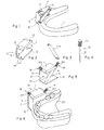
- FIG. 1 represents, schematically and in perspective, an embodiment of a gutter 1 according to the present invention.
- This gutter is produced conventionally from a dental mold (not shown in Figure 1), cast in an imprint of a patient's implantable jaw.
- the gutter 1 has a protrusion 2 outward from the shape of the molding.
- This protuberance 2 incorporates two tubes 3, 4, hollow and straight, whose axes respective are, for example, contained in two parallel planes between them and perpendicular to a plane in which the gutter 1. Tubes 3 and 4 are integrated into protrusion 2 during the manufacture of the gutter 1, as will be seen by the following.
- tubes 3 and 4 are in X-ray visible material to be located by a to scan.
- the axes of tubes 3 and 4 are not parallel between them and make, for example, an angle between 60 and 120 °, of preferably 90 °.
- Tubes 3 and 4 open on either side of substantially flat surfaces 5, 6 of the protrusion 2.
- the surfaces 5 and 6 are preferably parallel to the plane in which fits the gutter 1.
- tubes 3 and 4 The role of tubes 3 and 4 is twofold. On the one hand, they define two non-concurrent lines in reconstructed images from tomographic sections taken by scanner. On the other hand, they constitute means of receiving means removable connection of the gutter 1 to a mechanical support.
- FIG. 2 represents an embodiment of a support mechanical removable according to the present invention.
- the support 10 has the form general of a rigid stirrup, consisting of two plates 11, 12 protruding from a base 13.
- the plates 11 and 12 are separated one from the other and define, with the base 13, a housing 14 receiving the protrusion 2 of a gutter 1 such that shown in Figure 1.
- the plates 11 and 12 are preferably mutually parallel and perpendicular at base 13.
- Each plate 11, 12 comprises, according to the embodiment shown, two holes, respectively 15, 16 and 17, 18. These holes are aligned two by two along the axis of a tube 3, 4 ( Figure 3) to be, each, facing one end of a tube 3, 4 when tubes are placed between the plates 11 and 12.
- Tubes 3 and 4 are intended to be linked to the support 10, removably, by means of rigid rods 19 (FIG. 4) suitable for being engaged in the holes of the support 10 and in tubes 3 and 4.
- rods 19 FIG. 4
- the orifices 17, 18 of the other plate 12 are not necessarily through but can be blind holes open towards plate 11.
- the rods 19 have a length greater than that of the tubes 3, 4 plus the thickness of the plate 11 and the depth orifices 17, 18 of the plate 12, in order to allow their grip when they are in the engaged position.
- a portion 20 for gripping the rods 19 has, for example, a diameter greater than the diameter of a connecting portion 21, to constitute, both a means of gripping these rods and a stop when the portions 21 are pushed in if the four holes of the support 10 are through.
- the internal diameter of the tubes 3 and 4 is substantially equal to the outside diameter of the portions 21 of the rods 19 to the tolerances mechanical close to avoid play between the support 10 and the gutter 1 when these two elements are combined.
- FIG. 5 illustrates the association of the support 10 shown in Figure 2 with two tubes 3 and 4 held between the plates 11 and 12 by means of two rods 19.
- tubes 3 and 4 are not necessarily contained in two parallel planes, provided that their axes are not concurrent. However, one embodiment as shown in the figures constitutes an arrangement preferred for tubes 3 and 4 as it minimizes the size of the protrusion 2 at the periphery of the gutter 1 which must, moreover, be adapted to be placed in the mouth of a patient.
- the gutter is made from the plaster model of the dentition of the patient and of a support 10 according to the invention, associated with two tubes 3 and 4 connected by means of rods 19, that is to say to a structure as shown in Figure 5.
- Figure 6 illustrates the realization of a gutter 1 according to the invention.
- a curable material for example, a resin
- a curable material is poured, not only on the dental mold 22 in plaster reproducing the patient's teeth, but also in the housing 14 ( Figure 5) defined by the support 10, to constitute the protrusion 2 in which the tubes 3 are integrated and 4.
- the shape of the protrusion 2 is perfectly adapted to the shape of the housing 14 of the support 10.
- the constituent material of the gutter maybe any as long as it allows a location, by a scanner, of the tubes 3, 4 present in the protrusion 2.
- the practitioner determines, using the scanner images, the ideal drilling axis for placing a dental implant.
- This drilling axis is determined in the reference frame of the scanner, therefore also in the repository associated with tubes 3 and 4.
- An advantage of the present invention is that, thanks to the two tubes 3, 4 integrated therein, the gutter 1 is repositionable in the support 10, respecting its original position using two rods 19.
- the use of two rods prevents all movement of the gutter relative to the support.
- the gutter 1 can be linked, via the support 10, to a drilling robot whose repository can be the same as that associated with tubes 3, 4.
- the position of tubes 3, 4 is invariant with respect to support 10 when the gutter is associated with the support.
- the robot can therefore be operated in such a way so that its drilling axis exactly coincides with the position of the axis defined by the analysis of images from the scanner and the drilling is carried out in the gutter 1 exactly at the location and in the desired direction. This operation is of course repeated if several implants are planned.
- a third plate (not shown) can close one side of the housing 14, to facilitate the subsequent repositioning of the gutter 1 in the support 10.
- the housing 14 then remains open in two non-parallel directions to allow extraction and introduction of the extension 2 of the gutter 1.
- the support associated with the drilling robot is not necessarily the same as the support used for the realization of the gutter 1.
- plan to use several identical supports i.e. in which the positions of the plates 11, 12 one by relative to each other and in which the positions of the orifices 15, 16, 17, 18 are identical, so that the same gutter can be associated with different media.
- a support is permanently fixed to the drilling robot.
- an essential aspect of the present invention resides in the association of elements, rectilinear and localizable by a scanner, to a removable mechanical support allowing to preserve, without resorting to other measures, the same benchmark, in the scanner repository and in a mechanical repository.
- the present invention is capable of various variants and modifications which will appear to the man of art.
- different materials metal, ceramic
- these materials should be as resistant to wear as possible.
- the introduction of the rods 19 into the orifices of the support is a source of wear which must be avoided.
- ceramic or stainless steel to aluminum.
- the tubes 3, 4 will be chosen from a material which does not produce no artifacts during the scan, the trace on the scanner is sufficiently contrasted compared to tissue and bone and which has sufficient mechanical strength.
- titanium or aluminum will be chosen.
- two tubes are advantageously sufficient for placing implementation of the invention, provision may be made to associate more than two tubes to a support suitable for this purpose.
- others three-dimensional location systems that a scanner to X-rays can be used.
Description
Claims (10)
- Gouttière (1) adaptée à préparer la pose d'un implant dentaire, caractérisée en ce qu'elle comporte, dans une protubérance (2) latérale d'un contour externe, au moins deux tubes (3, 4) creux, rectilignes et non concourants, débouchant uniquement de part et d'autre de la protubérance et localisables aux rayons X.
- Gouttière selon la revendication 1, caractérisée en ce que les axes respectifs des tubes (3, 4) s'inscrivent dans deux plans parallèles entre eux et perpendiculaires à un plan dans lequel s'inscrit la gouttière (1).
- Gouttière selon la revendication 1 ou 2, caractérisée en ce que les axes des tubes (3, 4) font un angle compris entre 60 et 120° entre eux, de préférence, 90°.
- Support mécanique (10) d'une gouttière (1) adaptée à préparer la pose d'un implant dentaire, caractérisé en ce qu'il définit un logement ouvert (14) de réception d'une protubérance (2) d'une gouttière selon l'une quelconque des revendications 1 à 3, et en ce qu'il est pourvu d'orifices (15, 16 ; 17, 18) propres à être chacun en regard d'une extrémité d'un des tubes creux (3, 4) de la gouttière.
- Support selon la revendication 4, caractérisé en ce qu'il comporte au moins deux platines (11, 12) espacées l'une de l'autre et saillantes d'une embase (13), les deux platines comportant, chacune, au moins deux desdits orifices (15, 16 ; 17, 18).
- Support selon la revendication 5, caractérisé en ce qu'il est associé à au moins deux tiges (19) propres à être engagées, chacune, depuis un orifice (15, 16) traversant d'une des platines (11), dans le tube (3, 4) avec lequel l'orifice est en regard et dans un orif ice (17, 18) de l'autre platine (12).
- Système de transfert d'une position simulée d'un implant dentaire entre un scanner à rayons X et un robot de perçage d'une gouttière (1) de reproduction, en contre-forme, d'un moulage dentaire (22), caractérisé en ce qu'il comporte :au moins un support mécanique (10) conforme à l'une quelconque des revendications 4 à 6 ; etdes moyens (3, 4, 19) propres à lier, de façon amovible et dans une position reproductible, la gouttière (1) au support (10), la gouttière étant conforme à l'une quelconque des revendications 1 à 3.
- Système selon la revendication 7, caractérisé en ce que les deux éléments rectilignes (3, 4) intégrés à la gouttière(1) font partie des moyens de liaison de la gouttière au support.
- Procédé de positionnement d'implants dentaires au moyen d'un système selon la revendication 7 ou 8, caractérisé en ce qu'il comprend les étapes suivantes :positionnement d'au moins deux éléments rectilignes (3, 4), non concourants et visibles aux rayons X, dans un logement ouvert (14) d'un premier support mécanique (10) ;réalisation d'une gouttière (1), à partir d'un moulage dentaire (22) et du support mécanique (10), pour intégrer lesdits éléments (3, 4) dans la gouttière (1) ;mise en bouche de la gouttière (1), retirée du support (10), et réalisation de coupes tomographiques au scanner de cette gouttière et de la mâchoire correspondante ;détermination par un logiciel de simulation de la position optimale d'au moins un implant à réaliser ;détermination, dans un référentiel associé aux éléments rectilignes (3, 4), des axes de perçage idéaux déterminés par l'analyse des images scanner ;positionnement de la gouttière (1) dans un deuxième support (10), identique au premier, et lié à un système de robotique ;perçage, par le robot, de la gouttière (1) selon lesdits axes ; etremise en bouche de la gouttière (1) et utilisation de cette gouttière comme guide de perçage de la mâchoire pour la pose d'implants.
- Système selon la revendication 7 ou 8, pour la mise en oeuvre du procédé selon la revendication 9, caractérisé en ce que lesdits premier et deuxième supports sont un même support (10) équipé de moyens de fixation amovibles au robot de perçage.
Applications Claiming Priority (3)
| Application Number | Priority Date | Filing Date | Title |
|---|---|---|---|
| FR9702950 | 1997-03-07 | ||
| FR9702950A FR2760349B1 (fr) | 1997-03-07 | 1997-03-07 | Systeme pour preparer la pose d'un implant dentaire |
| PCT/FR1998/000412 WO1998040030A1 (fr) | 1997-03-07 | 1998-03-03 | Systeme pour preparer la pose d'un implant dentaire |
Publications (2)
| Publication Number | Publication Date |
|---|---|
| EP0979057A1 EP0979057A1 (fr) | 2000-02-16 |
| EP0979057B1 true EP0979057B1 (fr) | 2003-12-03 |
Family
ID=9504666
Family Applications (1)
| Application Number | Title | Priority Date | Filing Date |
|---|---|---|---|
| EP98913814A Expired - Lifetime EP0979057B1 (fr) | 1997-03-07 | 1998-03-03 | Systeme pour preparer la pose d'un implant dentaire |
Country Status (8)
| Country | Link |
|---|---|
| US (1) | US6296483B1 (fr) |
| EP (1) | EP0979057B1 (fr) |
| JP (1) | JP4075079B2 (fr) |
| AT (1) | ATE255378T1 (fr) |
| DE (1) | DE69820250T2 (fr) |
| ES (1) | ES2210737T3 (fr) |
| FR (1) | FR2760349B1 (fr) |
| WO (1) | WO1998040030A1 (fr) |
Families Citing this family (65)
| Publication number | Priority date | Publication date | Assignee | Title |
|---|---|---|---|---|
| US6790040B2 (en) | 1999-11-10 | 2004-09-14 | Implant Innovations, Inc. | Healing components for use in taking impressions and methods for making the same |
| DE10084790D2 (de) * | 2000-05-17 | 2003-09-04 | Gerd Neuschaefer | Vorrichtung zur Planung und Bohrung von Implantatlagern im menschlichen Kiefer |
| DE10114910B4 (de) * | 2001-03-26 | 2005-04-28 | Lb Medical Gmbh | Handstück für das Führen eines Effektors für die computerassistierte Behandlung |
| CN100556370C (zh) | 2001-03-26 | 2009-11-04 | Lb医药有限公司 | 用于对材料进行切除或加工处理的方法和器械系统 |
| FR2825614B1 (fr) | 2001-06-11 | 2004-04-02 | Vincent Bennani | Methode d'elaboration d'une armature montee sur implants adaptee pour supporter une prothese dentaire |
| BE1014288A3 (nl) * | 2001-07-06 | 2003-08-05 | Clerck Renu De | Werkwijze voor het vervaardigen van een suprastructuur en een overeenkomstige richtplaat. |
| CA2510405C (fr) * | 2002-01-16 | 2010-12-14 | Andrei Feldman | Modele d'implant buccal |
| US6913463B2 (en) * | 2002-02-20 | 2005-07-05 | Gordon D. Blacklock | Drilling guide for dental implantation |
| US20040161725A1 (en) * | 2003-02-13 | 2004-08-19 | Clement Milton A. | Dental implantation system, support, and related methods |
| US7461151B2 (en) * | 2003-11-13 | 2008-12-02 | International Business Machines Corporation | System and method enabling future messaging directives based on past participation via a history monitor |
| US7097451B2 (en) * | 2003-11-14 | 2006-08-29 | Brian Tang | Thermoplastic surgical template for performing dental implant osteotomies and method thereof |
| US7322824B2 (en) * | 2004-08-17 | 2008-01-29 | Schmitt Stephen M | Design and manufacture of dental implant restorations |
| FR2878429A1 (fr) * | 2004-11-29 | 2006-06-02 | Georges Antoine Creps | Dispositif et procede de forage pour l'insertion d'un implant dentaire |
| US7153132B2 (en) * | 2005-05-23 | 2006-12-26 | Tedesco James L | Mini-dental implant surgical stent |
| EP2921131B1 (fr) | 2005-06-30 | 2020-11-04 | Biomet 3i, LLC | Procédé de fabrication de composants d'implants dentaires |
| EP1922013A1 (fr) * | 2005-09-07 | 2008-05-21 | KAMER, Lukas | Procede pour realiser des organes de guidage pour guider un instrument chirurgical, et organe de guidage realise grace a ce procede |
| WO2007050436A2 (fr) | 2005-10-24 | 2007-05-03 | Biomet 3I, Inc. | Procedes pour la fabrication d'implants dentaires |
| US8257083B2 (en) | 2005-10-24 | 2012-09-04 | Biomet 3I, Llc | Methods for placing an implant analog in a physical model of the patient's mouth |
| US11219511B2 (en) | 2005-10-24 | 2022-01-11 | Biomet 3I, Llc | Methods for placing an implant analog in a physical model of the patient's mouth |
| JP4504911B2 (ja) * | 2005-11-30 | 2010-07-14 | イマグノーシス株式会社 | 医療用撮影マーカー |
| FR2896403B1 (fr) * | 2006-01-24 | 2008-08-01 | Francois Blouzard | Dispositif de guidage d'outil de percage pour la mise en place d'au moins un implant dentaire |
| US8506597B2 (en) * | 2011-10-25 | 2013-08-13 | Biomet Sports Medicine, Llc | Method and apparatus for interosseous membrane reconstruction |
| US8366442B2 (en) * | 2006-02-15 | 2013-02-05 | Bankruptcy Estate Of Voxelogix Corporation | Dental apparatus for radiographic and non-radiographic imaging |
| US7530810B2 (en) * | 2006-08-30 | 2009-05-12 | Clement Milton A | Dental fixture implantation system and associated method |
| US20080064008A1 (en) * | 2006-09-06 | 2008-03-13 | Dental Implant Technologies, Inc. | Methods for the virtual design and computer manufacture of intra oral devices |
| JP2008073440A (ja) * | 2006-09-25 | 2008-04-03 | Imagunooshisu Kk | インプラント植立ガイドの作製方法およびガイド用ブロック |
| US7835811B2 (en) * | 2006-10-07 | 2010-11-16 | Voxelogix Corporation | Surgical guides and methods for positioning artificial teeth and dental implants |
| US20090270723A1 (en) * | 2006-12-13 | 2009-10-29 | Han-Joon Kim | Medical imaging marker |
| FR2910804B1 (fr) | 2007-01-02 | 2010-03-12 | Michel Isidori | Dispositif de guidage et de modelage osseux pour la preparation de sites osseux en chirurgie |
| US20080286715A1 (en) * | 2007-05-16 | 2008-11-20 | Woncheol Choi | System and method for providing an image guided implant surgical guide |
| US8206153B2 (en) | 2007-05-18 | 2012-06-26 | Biomet 3I, Inc. | Method for selecting implant components |
| FR2919171B1 (fr) | 2007-07-23 | 2010-07-30 | Hospices Civils Lyon | Dispositif de positionnement et d'immobilisation dun guide chirurgical dans la bouche d'un patient. |
| EP2060240A3 (fr) | 2007-11-16 | 2009-08-12 | Biomet 3i, LLC | Composants à utiliser avec un guide chirurgical pour le placement d'implant dentaire |
| KR100852572B1 (ko) | 2008-03-11 | 2008-08-18 | (주)다스테크 | 치과용 의료 기기 |
| WO2009119620A1 (fr) * | 2008-03-27 | 2009-10-01 | Takebayashi Akira | Prothèse endovasculaire, procédé de reproduction utilisant cette dernière et procédé de détermination de la position des fils |
| EP3673861B1 (fr) | 2008-04-02 | 2022-12-07 | Neocis, Llc | Système d'implantation dentaire guidée |
| KR101536543B1 (ko) | 2008-04-15 | 2015-07-14 | 바이오메트 쓰리아이 엘엘씨 | 정확한 뼈와 연조직 디지털 치아 모델의 형성 방법 |
| EP3000430B1 (fr) | 2008-04-16 | 2017-11-15 | Biomet 3i, LLC | Procédé de developement virtuel d'un guide chirurgical pour implant dentaire |
| TW201000078A (en) * | 2008-06-26 | 2010-01-01 | Pou Yu Biotechnology Co Ltd | Manufacturing method for the guiding board of dental implant surgical operation |
| US20100203479A1 (en) * | 2009-02-06 | 2010-08-12 | Bulloch Scott E | Dental implant system and methods |
| US9039414B2 (en) * | 2009-02-06 | 2015-05-26 | Scott E. Bulloch | Drill guide pin, shank, cannulated drill bit, and driver for creating a hole in a bone |
| TWI535424B (zh) | 2009-03-13 | 2016-06-01 | 神農資訊股份有限公司 | 植牙手術模板製造系統及方法 |
| DE102009003183A1 (de) * | 2009-05-18 | 2010-11-25 | Gäßler, Guido | Verfahren zur Herstellung einer zahnärztlichen Schablone und zahnärztliche Schablone |
| US8348669B1 (en) | 2009-11-04 | 2013-01-08 | Bankruptcy Estate Of Voxelogix Corporation | Surgical template and method for positioning dental casts and dental implants |
| WO2012039017A1 (fr) * | 2010-09-21 | 2012-03-29 | 株式会社インプラントデント | Outil de fabrication de guide chirurgical et procédé de fabrication de guide chirurgical |
| ES2477288T3 (es) | 2010-12-07 | 2014-07-16 | Biomet 3I, Llc | Elemento de exploración universal para su uso en un implante dental y en análogos de implante dental |
| EP2709554B1 (fr) | 2011-05-16 | 2019-09-11 | Biomet 3i, LLC | Dent pilier provisoire combinant caractéristiques d'exploration et caractère provisoire |
| US9089382B2 (en) | 2012-01-23 | 2015-07-28 | Biomet 3I, Llc | Method and apparatus for recording spatial gingival soft tissue relationship to implant placement within alveolar bone for immediate-implant placement |
| US9452032B2 (en) | 2012-01-23 | 2016-09-27 | Biomet 3I, Llc | Soft tissue preservation temporary (shell) immediate-implant abutment with biological active surface |
| FR2994076B1 (fr) * | 2012-07-31 | 2016-12-30 | Guillaume Champleboux | Procede et dispositif de preparation a la pose d'un implant dentaire |
| US10813729B2 (en) | 2012-09-14 | 2020-10-27 | Biomet 3I, Llc | Temporary dental prosthesis for use in developing final dental prosthesis |
| US10098714B2 (en) * | 2012-12-19 | 2018-10-16 | Align Technology, Inc. | Apparatus and method for optically scanning an object in registration with a reference pattern |
| US10617489B2 (en) | 2012-12-19 | 2020-04-14 | Align Technology, Inc. | Creating a digital dental model of a patient's teeth using interproximal information |
| US9668829B2 (en) * | 2012-12-19 | 2017-06-06 | Align Technology, Inc. | Methods and systems for dental procedures |
| US8926328B2 (en) | 2012-12-27 | 2015-01-06 | Biomet 3I, Llc | Jigs for placing dental implant analogs in models and methods of doing the same |
| US9839496B2 (en) | 2013-02-19 | 2017-12-12 | Biomet 3I, Llc | Patient-specific dental prosthesis and gingival contouring developed by predictive modeling |
| US20140272793A1 (en) * | 2013-03-15 | 2014-09-18 | Grant Dental Technology Corporation | Dental implant instrumentation and methods |
| ES2728867T3 (es) | 2013-04-09 | 2019-10-29 | Biomet 3I Llc | Implante dental con superficie superior codificada |
| EP3094283A4 (fr) | 2013-12-20 | 2018-01-24 | Biomet 3i, LLC | Système dentaire pour développer des prothèses sur mesure par balayage d'éléments codés |
| US9283055B2 (en) | 2014-04-01 | 2016-03-15 | FPJ Enterprises, LLC | Method for establishing drill trajectory for dental implants |
| US9700390B2 (en) | 2014-08-22 | 2017-07-11 | Biomet 3I, Llc | Soft-tissue preservation arrangement and method |
| US9962234B2 (en) | 2014-12-24 | 2018-05-08 | Isethco Llc | Disposable surgical intervention guides, methods, and kits |
| US10136968B2 (en) | 2014-12-24 | 2018-11-27 | Isethco Llc | Disposable surgical intervention guides, methods, and kits |
| WO2016144970A1 (fr) | 2015-03-09 | 2016-09-15 | Chu Stephen J | Pontique ovoïde gingival et ses procédés d'utilisation |
| JP6593180B2 (ja) * | 2016-01-08 | 2019-10-23 | 株式会社デンソー | 医療支援装置 |
Family Cites Families (9)
| Publication number | Priority date | Publication date | Assignee | Title |
|---|---|---|---|---|
| US3919772A (en) * | 1973-06-04 | 1975-11-18 | Joseph J Lenczycki | Dental implant assembly and method for attaching the same to the jaw bone |
| US5015183A (en) | 1989-08-07 | 1991-05-14 | Fenick Thomas J | Locating device and method of placing a tooth implant |
| US5133660A (en) * | 1989-08-07 | 1992-07-28 | Fenick Thomas J | Device for locating the optimum position for a tooth implant |
| US5320529A (en) * | 1992-09-09 | 1994-06-14 | Howard C. Weitzman | Method and apparatus for locating an ideal site for a dental implant and for the precise surgical placement of that implant |
| FR2705027B1 (fr) | 1993-05-11 | 1995-07-28 | Univ Joseph Fourier | Gouttière pour préparer la pose d'un implant dentaire. |
| IT1270942B (it) * | 1993-05-14 | 1997-05-26 | Antonio Cascione | Dima radiografico-chirurgica orientabile per ipianti nelle ossa mascellari. |
| US5556278A (en) * | 1994-09-07 | 1996-09-17 | Meitner; Sean W. | Method for making and using a template for a dental implant osteotomy and components relating thereto |
| US5580244A (en) * | 1995-03-02 | 1996-12-03 | White; Dennis J. | Method and apparatus for taking dental impressions |
| US5718579A (en) * | 1995-12-05 | 1998-02-17 | Kennedy; Brent D. | Drill guide kit |
-
1997
- 1997-03-03 US US09/380,889 patent/US6296483B1/en not_active Expired - Lifetime
- 1997-03-07 FR FR9702950A patent/FR2760349B1/fr not_active Expired - Fee Related
-
1998
- 1998-03-03 ES ES98913814T patent/ES2210737T3/es not_active Expired - Lifetime
- 1998-03-03 DE DE69820250T patent/DE69820250T2/de not_active Expired - Lifetime
- 1998-03-03 EP EP98913814A patent/EP0979057B1/fr not_active Expired - Lifetime
- 1998-03-03 WO PCT/FR1998/000412 patent/WO1998040030A1/fr active IP Right Grant
- 1998-03-03 AT AT98913814T patent/ATE255378T1/de active
- 1998-03-03 JP JP53926898A patent/JP4075079B2/ja not_active Expired - Fee Related
Also Published As
| Publication number | Publication date |
|---|---|
| ES2210737T3 (es) | 2004-07-01 |
| JP2001517114A (ja) | 2001-10-02 |
| ATE255378T1 (de) | 2003-12-15 |
| US6296483B1 (en) | 2001-10-02 |
| DE69820250T2 (de) | 2004-10-14 |
| EP0979057A1 (fr) | 2000-02-16 |
| WO1998040030A1 (fr) | 1998-09-17 |
| FR2760349B1 (fr) | 1999-05-28 |
| FR2760349A1 (fr) | 1998-09-11 |
| DE69820250D1 (de) | 2004-01-15 |
| JP4075079B2 (ja) | 2008-04-16 |
Similar Documents
| Publication | Publication Date | Title |
|---|---|---|
| EP0979057B1 (fr) | Systeme pour preparer la pose d'un implant dentaire | |
| EP1952783B1 (fr) | Dispositif de reperage et de mesure de parametres anatomiques faciaux | |
| EP0091876B1 (fr) | Dispositif de prise d'empreinte par des moyens optiques, notamment en vue de la réalisation automatique de prothèses | |
| FR2994076A1 (fr) | Procede et dispositif de preparation a la pose d'un implant dentaire | |
| EP1006931B1 (fr) | Procede pour realiser une prothese dentaire | |
| EP2037834B1 (fr) | Procédé de fabrication d'une prothèse osseuse ou d'une simulation preimplantaire et appareillage mis en oeuvre | |
| WO2009027316A1 (fr) | Procédé de fabrication d'une prothèse dentaire et d'un guide chirurgical y afférant | |
| WO2009127536A2 (fr) | Procédé de conception d'un appareil orthodontique | |
| EP1370190B1 (fr) | Procédé de réalisation d' éléments de restauration dentaire | |
| FR2705027A1 (fr) | Gouttière pour préparer la pose d'un implant dentaire. | |
| EP3817689B1 (fr) | Dispositif de cicatrisation pour implant dentaire | |
| WO2002100290A1 (fr) | Methode d'elaboration d'une armature de support d'une prothese dentaire, guide chirurgical utilisable et armature obtenue | |
| EP0954252B1 (fr) | Dispositif de determination d'un deplacement entre deux moulages dentaires au moyen d'un scanner a rayons x | |
| EP2149345A1 (fr) | Dispositif de positionnement d'un axe de référence en vue de la détermination d'un axe de perçage pour la mise en place d'au moins un implant dentaire | |
| US20130122454A1 (en) | Impression Device and Method for Three-Dimensional Acquisition of Intraoral Structures, and Corresponding Scanning Device | |
| ES2286175T3 (es) | Procedimiento para la fabricacion de una protesis dental. | |
| FR2882250A1 (fr) | Dispositifs de guidage et de coupe pour la preparation de sites osseux en chirurgie implantaire | |
| WO2012101914A1 (fr) | Outil d'alignement de positions pour la dentisterie, et procédé d'obtention d'occlusion dentaire associé | |
| FR2808669A1 (fr) | Procede, systeme et guide de reperage pour pose d'implant dentaire | |
| BE1027582B1 (fr) | Procédé de production d'une grille d'un implant juxta-osseux | |
| KR20240033614A (ko) | 측정 구조물을 이용한 임플란트용 교합 측정방법 및 이의 측정 구조물 | |
| FR2735679A1 (fr) | Procede pour realiser une prothese dentaire | |
| FR3018445A1 (fr) | Support d'implant et instrument comprenant un tel support | |
| FR2773467A1 (fr) | Gabarit pour la localisation d'un axe de forage optimal dans un os maxillaire d'un patient, et son procede de fabrication | |
| JP2004209145A (ja) | 歯科補綴物の製造方法 |
Legal Events
| Date | Code | Title | Description |
|---|---|---|---|
| PUAI | Public reference made under article 153(3) epc to a published international application that has entered the european phase |
Free format text: ORIGINAL CODE: 0009012 |
|
| 17P | Request for examination filed |
Effective date: 19990909 |
|
| AK | Designated contracting states |
Kind code of ref document: A1 Designated state(s): AT BE CH DE ES FR GB IT LI SE |
|
| 17Q | First examination report despatched |
Effective date: 20020807 |
|
| GRAH | Despatch of communication of intention to grant a patent |
Free format text: ORIGINAL CODE: EPIDOS IGRA |
|
| GRAS | Grant fee paid |
Free format text: ORIGINAL CODE: EPIDOSNIGR3 |
|
| GRAA | (expected) grant |
Free format text: ORIGINAL CODE: 0009210 |
|
| AK | Designated contracting states |
Kind code of ref document: B1 Designated state(s): AT BE CH DE ES FR GB IT LI SE |
|
| REG | Reference to a national code |
Ref country code: GB Ref legal event code: FG4D Free format text: NOT ENGLISH |
|
| REG | Reference to a national code |
Ref country code: CH Ref legal event code: EP |
|
| GBT | Gb: translation of ep patent filed (gb section 77(6)(a)/1977) |
Effective date: 20031203 |
|
| REG | Reference to a national code |
Ref country code: CH Ref legal event code: NV Representative=s name: MOINAS & SAVOYE SA |
|
| REF | Corresponds to: |
Ref document number: 69820250 Country of ref document: DE Date of ref document: 20040115 Kind code of ref document: P |
|
| REG | Reference to a national code |
Ref country code: SE Ref legal event code: TRGR |
|
| REG | Reference to a national code |
Ref country code: ES Ref legal event code: FG2A Ref document number: 2210737 Country of ref document: ES Kind code of ref document: T3 |
|
| PLBE | No opposition filed within time limit |
Free format text: ORIGINAL CODE: 0009261 |
|
| STAA | Information on the status of an ep patent application or granted ep patent |
Free format text: STATUS: NO OPPOSITION FILED WITHIN TIME LIMIT |
|
| 26N | No opposition filed |
Effective date: 20040906 |
|
| PG25 | Lapsed in a contracting state [announced via postgrant information from national office to epo] |
Ref country code: IT Free format text: LAPSE BECAUSE OF NON-PAYMENT OF DUE FEES Effective date: 20090303 |
|
| PGRI | Patent reinstated in contracting state [announced from national office to epo] |
Ref country code: IT Effective date: 20110616 |
|
| PGFP | Annual fee paid to national office [announced via postgrant information from national office to epo] |
Ref country code: CH Payment date: 20130325 Year of fee payment: 16 Ref country code: GB Payment date: 20130327 Year of fee payment: 16 Ref country code: ES Payment date: 20130326 Year of fee payment: 16 Ref country code: SE Payment date: 20130327 Year of fee payment: 16 |
|
| PGFP | Annual fee paid to national office [announced via postgrant information from national office to epo] |
Ref country code: AT Payment date: 20130220 Year of fee payment: 16 |
|
| PGFP | Annual fee paid to national office [announced via postgrant information from national office to epo] |
Ref country code: BE Payment date: 20130327 Year of fee payment: 16 |
|
| REG | Reference to a national code |
Ref country code: CH Ref legal event code: PL |
|
| REG | Reference to a national code |
Ref country code: SE Ref legal event code: EUG |
|
| REG | Reference to a national code |
Ref country code: AT Ref legal event code: MM01 Ref document number: 255378 Country of ref document: AT Kind code of ref document: T Effective date: 20140303 |
|
| GBPC | Gb: european patent ceased through non-payment of renewal fee |
Effective date: 20140303 |
|
| PG25 | Lapsed in a contracting state [announced via postgrant information from national office to epo] |
Ref country code: SE Free format text: LAPSE BECAUSE OF NON-PAYMENT OF DUE FEES Effective date: 20140304 |
|
| PG25 | Lapsed in a contracting state [announced via postgrant information from national office to epo] |
Ref country code: CH Free format text: LAPSE BECAUSE OF NON-PAYMENT OF DUE FEES Effective date: 20140331 Ref country code: GB Free format text: LAPSE BECAUSE OF NON-PAYMENT OF DUE FEES Effective date: 20140303 Ref country code: LI Free format text: LAPSE BECAUSE OF NON-PAYMENT OF DUE FEES Effective date: 20140331 |
|
| PG25 | Lapsed in a contracting state [announced via postgrant information from national office to epo] |
Ref country code: AT Free format text: LAPSE BECAUSE OF NON-PAYMENT OF DUE FEES Effective date: 20140303 |
|
| REG | Reference to a national code |
Ref country code: ES Ref legal event code: FD2A Effective date: 20150428 |
|
| PG25 | Lapsed in a contracting state [announced via postgrant information from national office to epo] |
Ref country code: ES Free format text: LAPSE BECAUSE OF NON-PAYMENT OF DUE FEES Effective date: 20140304 |
|
| REG | Reference to a national code |
Ref country code: FR Ref legal event code: PLFP Year of fee payment: 19 |
|
| REG | Reference to a national code |
Ref country code: FR Ref legal event code: PLFP Year of fee payment: 20 |
|
| PG25 | Lapsed in a contracting state [announced via postgrant information from national office to epo] |
Ref country code: BE Free format text: LAPSE BECAUSE OF NON-PAYMENT OF DUE FEES Effective date: 20140331 |
|
| PGFP | Annual fee paid to national office [announced via postgrant information from national office to epo] |
Ref country code: FR Payment date: 20170426 Year of fee payment: 20 Ref country code: DE Payment date: 20170427 Year of fee payment: 20 |
|
| PGFP | Annual fee paid to national office [announced via postgrant information from national office to epo] |
Ref country code: IT Payment date: 20170421 Year of fee payment: 20 |
|
| REG | Reference to a national code |
Ref country code: DE Ref legal event code: R071 Ref document number: 69820250 Country of ref document: DE |