EP0978902A2 - Connecteur à sertissage pour câble plat - Google Patents
Connecteur à sertissage pour câble plat Download PDFInfo
- Publication number
- EP0978902A2 EP0978902A2 EP99115539A EP99115539A EP0978902A2 EP 0978902 A2 EP0978902 A2 EP 0978902A2 EP 99115539 A EP99115539 A EP 99115539A EP 99115539 A EP99115539 A EP 99115539A EP 0978902 A2 EP0978902 A2 EP 0978902A2
- Authority
- EP
- European Patent Office
- Prior art keywords
- crimp connector
- flat
- flat cable
- contact elements
- carrier element
- Prior art date
- Legal status (The legal status is an assumption and is not a legal conclusion. Google has not performed a legal analysis and makes no representation as to the accuracy of the status listed.)
- Withdrawn
Links
Images


Classifications
-
- H—ELECTRICITY
- H01—ELECTRIC ELEMENTS
- H01R—ELECTRICALLY-CONDUCTIVE CONNECTIONS; STRUCTURAL ASSOCIATIONS OF A PLURALITY OF MUTUALLY-INSULATED ELECTRICAL CONNECTING ELEMENTS; COUPLING DEVICES; CURRENT COLLECTORS
- H01R12/00—Structural associations of a plurality of mutually-insulated electrical connecting elements, specially adapted for printed circuits, e.g. printed circuit boards [PCB], flat or ribbon cables, or like generally planar structures, e.g. terminal strips, terminal blocks; Coupling devices specially adapted for printed circuits, flat or ribbon cables, or like generally planar structures; Terminals specially adapted for contact with, or insertion into, printed circuits, flat or ribbon cables, or like generally planar structures
- H01R12/50—Fixed connections
- H01R12/59—Fixed connections for flexible printed circuits, flat or ribbon cables or like structures
- H01R12/61—Fixed connections for flexible printed circuits, flat or ribbon cables or like structures connecting to flexible printed circuits, flat or ribbon cables or like structures
- H01R12/613—Fixed connections for flexible printed circuits, flat or ribbon cables or like structures connecting to flexible printed circuits, flat or ribbon cables or like structures by means of interconnecting elements
-
- H—ELECTRICITY
- H01—ELECTRIC ELEMENTS
- H01R—ELECTRICALLY-CONDUCTIVE CONNECTIONS; STRUCTURAL ASSOCIATIONS OF A PLURALITY OF MUTUALLY-INSULATED ELECTRICAL CONNECTING ELEMENTS; COUPLING DEVICES; CURRENT COLLECTORS
- H01R12/00—Structural associations of a plurality of mutually-insulated electrical connecting elements, specially adapted for printed circuits, e.g. printed circuit boards [PCB], flat or ribbon cables, or like generally planar structures, e.g. terminal strips, terminal blocks; Coupling devices specially adapted for printed circuits, flat or ribbon cables, or like generally planar structures; Terminals specially adapted for contact with, or insertion into, printed circuits, flat or ribbon cables, or like generally planar structures
- H01R12/50—Fixed connections
- H01R12/59—Fixed connections for flexible printed circuits, flat or ribbon cables or like structures
- H01R12/65—Fixed connections for flexible printed circuits, flat or ribbon cables or like structures characterised by the terminal
- H01R12/69—Fixed connections for flexible printed circuits, flat or ribbon cables or like structures characterised by the terminal deformable terminals, e.g. crimping terminals
Definitions
- the present invention relates to a crimp connector for Flat cables and a method for connecting two Flat cables using such a crimp connector.
- the crimp connector comprises therefore a carrier element for two flat cables, which is essentially transverse to the longitudinal extension of the flat lines to be connected extends, at least one contact element, which is essentially longitudinal of the flat cables and which extends to the carrier element is attached, with one conductor track of the flat cables an electrically conductive contact element is provided , and wherein a plurality of holding members on each contact element is provided, which is permanent with the flat cables can be brought into engagement.
- crimp connector 1 shows a crimp connector 1 in plan view and shown in perspective.
- a carrier element 2 is arranged, which is transverse to a
- a plurality of contact elements 3 runs in this embodiment are provided in triplicate.
- the three contact elements 3 are only given as examples and with the crimp connector 1 according to the invention any number of conductor tracks 10 (FIG. 3) one Flat line 11 or 12 are connected. In the shown In the exemplary embodiment, there are three conductor tracks 10 connected to two to be connected flat lines 11 and 12, and the can be connected by one contact element 3 each.
- the crimp connector 1 comprises the carrier element 2 made of an electrically insulating material, for example Plastic, the carrier element 2 a substantially cuboid shape, which has a clear longitudinal extension having.
- the carrier element 2 extends in Use across a flat cable 11 or 12 (see Figure 6) so that the contact elements arranged on the carrier element 2 3, which is essentially parallel to the flat cable 11 or 12 run perpendicular to the carrier element 2 are arranged.
- the contact elements 3 are on the underside ( Figure 2) of the support member 2 attached.
- the attachment can already in one injection molding of the carrier element 2 Operation take place, in which case the contact elements 3 in the Injection mold are to be arranged, or else by other Known fastening devices 7 take place.
- the contact elements 3 are electrically conductive parts, for example from sheet metal, their shape by punching and bending is preserved.
- On the elongated, essentially flat Contact elements 3 are holding members 4 on the one hand provided, and on the other hand, cutting devices 5 formed are.
- the holding members 4 are substantially triangular in shape Jagged or claws formed on the long sides of the contact elements 3, spaced apart from one another, are provided are.
- the holding members 4 engage in the assembly of the crimp connector into the openings 8 of the flat cable 11 or 12 on.
- the holding members 4 are almost at right angles from the Main plane of the contact elements 3 bent and for reasons an easier insertion into the openings 8 with a rounded tip.
- the cutting devices 5 are in the form of sharp-edged Tips that are preferably punched out triangular and after are bent at the top.
- the cutting devices 5 are lying in the middle of the contact elements 3, to each other spaced, preferably provided several times.
- the peaks of the cutting devices 5 penetrate during the assembly of the Crimpconnectors the flat cable 11 or 12 and the one on it located conductor track 10 ( Figure 5). This will make it a safe one Contact between the conductor track 10 and the contact element 3 guaranteed.
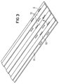
- the flat cable 11 ( Figure 3, 4 and 5) is at the end where the crimp connector 1 is to be assembled, cut cleanly and punched with a suitable tool. Advantageously can do this in one operation with one tool respectively.
- the openings 8 are at one end in the Flat cable introduced that the end of the flat cable the carrier element 2 of the crimp connector 1 is flush and that the holding members 4 of the crimp connector 1, the openings 8th reach through, as shown in Figure 5.
- the support element 2 thus serves as a stop for the flat cable and thus as a positioning aid between flat cable (s) and crimp connector 1.
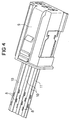
- a replacement connector 9 is mounted ( Figures 4 and 5).
- the assembly of the replacement connector 9 on the flat cable 11 can, since outside a vehicle possible, preferably by welding respectively. Crimping can already take place in this step of the crimp connector 1 on the flat cable 11.
- the crimping is done.
- the holding members 4 bent and preferably also with the conductor tracks 10 engaged.
- the cutting devices 5 are also bent over the flat cables 11 and hold 12 securely.
- the crimp connection is strapped with an insulating tape, after connecting the flat cables 11, 12 an electrical Isolate the crimp connector 1 from the outside by means of Insulating tape or a separate housing, which preferably consists of plastic.
- the total thickness of the flat cables 11 and 12 is only a few 1/10 mm, the pitch of the conductor tracks 10 is usually 2.54 mm. As a result of this very small Dimensions is an extremely precise attachment of the crimp connector 1 essential.
- the present invention solves this technical problem Help of the previously introduced on the flat cables 11 and 12 Openings 8, which allow secure positioning.
Landscapes
- Multi-Conductor Connections (AREA)
- Coupling Device And Connection With Printed Circuit (AREA)
Applications Claiming Priority (2)
| Application Number | Priority Date | Filing Date | Title |
|---|---|---|---|
| DE19835022 | 1998-08-03 | ||
| DE19835022 | 1998-08-03 |
Publications (2)
| Publication Number | Publication Date |
|---|---|
| EP0978902A2 true EP0978902A2 (fr) | 2000-02-09 |
| EP0978902A3 EP0978902A3 (fr) | 2001-02-14 |
Family
ID=7876305
Family Applications (1)
| Application Number | Title | Priority Date | Filing Date |
|---|---|---|---|
| EP99115539A Withdrawn EP0978902A3 (fr) | 1998-08-03 | 1999-08-02 | Connecteur à sertissage pour câble plat |
Country Status (1)
| Country | Link |
|---|---|
| EP (1) | EP0978902A3 (fr) |
Cited By (2)
| Publication number | Priority date | Publication date | Assignee | Title |
|---|---|---|---|---|
| DE10161857A1 (de) * | 2001-12-17 | 2003-07-10 | Wezag Gmbh | Vorrichtung zum leitenden Verbinden mindestens eines Kontaktes an einer Leiterbahn in einem ein- oder mehradrigen Flachbandkabel |
| DE102004061425A1 (de) * | 2004-12-21 | 2006-07-06 | Tyco Electronics Amp Gmbh | Elektrischer Verbinder, insbesondere Crimp-Verbinder |
Family Cites Families (4)
| Publication number | Priority date | Publication date | Assignee | Title |
|---|---|---|---|---|
| US3960430A (en) * | 1974-10-29 | 1976-06-01 | Amp Incorporated | Flat wiring system and crimped connection |
| US4784623A (en) * | 1987-04-03 | 1988-11-15 | Amp Incorporated | Mass terminable flat flexible cable to pin connector |
| JPH0754720B2 (ja) * | 1987-04-10 | 1995-06-07 | フレキシブルプリント回路板用電気接続端子 | |
| US5219303A (en) * | 1992-02-13 | 1993-06-15 | Amp Incorporated | Mid-cable electrical termination |
-
1999
- 1999-08-02 EP EP99115539A patent/EP0978902A3/fr not_active Withdrawn
Cited By (3)
| Publication number | Priority date | Publication date | Assignee | Title |
|---|---|---|---|---|
| DE10161857A1 (de) * | 2001-12-17 | 2003-07-10 | Wezag Gmbh | Vorrichtung zum leitenden Verbinden mindestens eines Kontaktes an einer Leiterbahn in einem ein- oder mehradrigen Flachbandkabel |
| DE10161857C2 (de) * | 2001-12-17 | 2003-10-23 | Wezag Gmbh | Vorrichtung zum leitenden Verbinden mindestens eines Kontaktes an einer Leiterbahn in einem ein- oder mehradrigen Flachbandkabel |
| DE102004061425A1 (de) * | 2004-12-21 | 2006-07-06 | Tyco Electronics Amp Gmbh | Elektrischer Verbinder, insbesondere Crimp-Verbinder |
Also Published As
| Publication number | Publication date |
|---|---|
| EP0978902A3 (fr) | 2001-02-14 |
Similar Documents
| Publication | Publication Date | Title |
|---|---|---|
| DE3687774T2 (de) | Anschluesse eines elektrischen mehradrigen kabels sowie verfahren und vorrichtung zum herstellen derselben. | |
| DE3225175C2 (de) | Abschirmanschluß | |
| DE2414571C2 (fr) | ||
| EP3025396B1 (fr) | Terminal permettant la mise en contact électrique d'un conducteur électrique | |
| DE2725508A1 (de) | Drahtschneid- und -einsetzgeraet | |
| DE19632820A1 (de) | Verteilerplatte für elektrische Anschlüsse | |
| DE4413756C1 (de) | Gehäuse für einen Steckverbinder | |
| DE69401671T2 (de) | Elektrischer Sammelverbinder | |
| DE19832011B4 (de) | Flachbandleitung mit einem zum lösbaren Verbinden vorgesehenen Anschlußbereich | |
| DE3942276C2 (fr) | ||
| DE102010034790A1 (de) | Vorrichtung und Verfahren zur Kontaktierung eines elektrischen Leiters mit einer Leiterbahn und Kontaktträger für eine solche Vorrichtung | |
| DE19832012A1 (de) | Anschlußanordnung für Flachbandleitungen | |
| DE4331036C2 (de) | Schneidklemm-Verbindungsstecker | |
| DE202010011546U1 (de) | Vorrichtung zur Kontaktierung eines elektrischen Leiters mit einer Leiterbahn und Kontaktträger für eine solche Vorrichtung | |
| DE102021128871A1 (de) | Steckverbinder, Steckverbinderanordnung, sowie ein Werkzeug und Verfahren zur Montage der Steckverbinderanordnung | |
| DE4320539C2 (de) | Leitungsdraht-Verbindungsklemme | |
| EP0978902A2 (fr) | Connecteur à sertissage pour câble plat | |
| DE102008008544A1 (de) | Feder-Klammer-Direktkontaktierung | |
| DE19749145A1 (de) | Elektrischer Anschlußbehälter | |
| DE102008054983A1 (de) | Kontaktierungsstecker sowie Kontaktierungsverbindung | |
| DE4017725C2 (fr) | ||
| EP1780843B1 (fr) | Douille de connexion électrique pour télécommunication et la transmission de données | |
| DE20019171U1 (de) | Crimpkontakt für Leiterplatten | |
| EP0905818A2 (fr) | Système de connecteur hyperfréquence et méthode d'assemblage | |
| EP0987797B1 (fr) | Dispositif de raccordement électrique |
Legal Events
| Date | Code | Title | Description |
|---|---|---|---|
| PUAI | Public reference made under article 153(3) epc to a published international application that has entered the european phase |
Free format text: ORIGINAL CODE: 0009012 |
|
| AK | Designated contracting states |
Kind code of ref document: A2 Designated state(s): AT BE CH CY DE DK ES FI FR GB GR IE IT LI LU MC NL PT SE |
|
| AX | Request for extension of the european patent |
Free format text: AL;LT;LV;MK;RO;SI |
|
| PUAL | Search report despatched |
Free format text: ORIGINAL CODE: 0009013 |
|
| AK | Designated contracting states |
Kind code of ref document: A3 Designated state(s): AT BE CH CY DE DK ES FI FR GB GR IE IT LI LU MC NL PT SE |
|
| AX | Request for extension of the european patent |
Free format text: AL;LT;LV;MK;RO;SI |
|
| RAP1 | Party data changed (applicant data changed or rights of an application transferred) |
Owner name: TYCO ELECTRONICS LOGISTICS AG |
|
| AKX | Designation fees paid | ||
| STAA | Information on the status of an ep patent application or granted ep patent |
Free format text: STATUS: THE APPLICATION IS DEEMED TO BE WITHDRAWN |
|
| 18D | Application deemed to be withdrawn |
Effective date: 20010815 |
|
| REG | Reference to a national code |
Ref country code: DE Ref legal event code: 8566 |