EP0977421A2 - Adapter für die Abtastung von Transparentfilmen mit einem reflektierenden Dokumentabtaster - Google Patents
Adapter für die Abtastung von Transparentfilmen mit einem reflektierenden Dokumentabtaster Download PDFInfo
- Publication number
- EP0977421A2 EP0977421A2 EP99305519A EP99305519A EP0977421A2 EP 0977421 A2 EP0977421 A2 EP 0977421A2 EP 99305519 A EP99305519 A EP 99305519A EP 99305519 A EP99305519 A EP 99305519A EP 0977421 A2 EP0977421 A2 EP 0977421A2
- Authority
- EP
- European Patent Office
- Prior art keywords
- adapter
- scanner
- platen
- scan line
- light
- Prior art date
- Legal status (The legal status is an assumption and is not a legal conclusion. Google has not performed a legal analysis and makes no representation as to the accuracy of the status listed.)
- Withdrawn
Links
Images


Classifications
-
- H—ELECTRICITY
- H04—ELECTRIC COMMUNICATION TECHNIQUE
- H04N—PICTORIAL COMMUNICATION, e.g. TELEVISION
- H04N1/00—Scanning, transmission or reproduction of documents or the like, e.g. facsimile transmission; Details thereof
- H04N1/04—Scanning arrangements, i.e. arrangements for the displacement of active reading or reproducing elements relative to the original or reproducing medium, or vice versa
- H04N1/10—Scanning arrangements, i.e. arrangements for the displacement of active reading or reproducing elements relative to the original or reproducing medium, or vice versa using flat picture-bearing surfaces
-
- H—ELECTRICITY
- H04—ELECTRIC COMMUNICATION TECHNIQUE
- H04N—PICTORIAL COMMUNICATION, e.g. TELEVISION
- H04N2201/00—Indexing scheme relating to scanning, transmission or reproduction of documents or the like, and to details thereof
- H04N2201/04—Scanning arrangements
- H04N2201/0402—Arrangements not specific to a particular one of the scanning methods covered by groups H04N1/04 - H04N1/207
- H04N2201/0418—Arrangements not specific to a particular one of the scanning methods covered by groups H04N1/04 - H04N1/207 capable of scanning transmissive and reflective originals at a single scanning station
Definitions
- This invention relates generally to optical scanners and more specifically to an adapter for scanning transparent images such as slides and negatives.
- Document scanners convert a visible image on a document or photograph, or a image in a transparent medium, into an electronic form suitable for copying, storing or processing by a computer.
- a document scanner may be a separate device or a document scanner may be a part of a copier, part of a facsimile machine. or part of a multipurpose device.
- Reflective document scanners typically have a controlled source of light which is reflected off the surface of a document, through an optics system, and onto an array of photosensitive devices. The photosensitive devices convert received light intensity into an electronic signal.
- Transparency scanners pass light through a transparent image, for example a photographic positive slide, through an optics system, and then onto an array of photosensitive devices.
- Reflective document scanners may be adapted to scan transparent images by providing a separate light source to back-light the image.
- U.S. Patent Number 5,463,217 describes a completely passive adapter for scanning transparent images in a reflective scanner without requiring a separate light source for back lighting.
- a light source in the reflective scanner provides light which passes outside the area of the transparent image.
- the adapter captures light which passes outside the area of the transparent image and reflects the light through the transparent image.
- the reflected light reenters the scanner along the optical path required by scanner internal optics.
- the various embodiments described in Sobol et al. are suitable for a fixed scanner optical path. However, when a new scanner is developed, the angle of the adapter mirrors may need to change to accommodate a different optical path within the new scanner.
- the present invention seeks to provide an adapter for scanning a transparent image.
- an adapter as specified in claim 1.
- the preferred embodiment can provide an adjustable adapter that can be adjusted to different optical paths in different scanners, thereby permitting a single adapter to be used with multiple scanner designs.
- the lamp leads the scan line during scanning movement, and for other scanners, the lamp lags the scan line during scanning movement.
- the preferred embodiment can ensure that for either case, when the scan line is within the image to be captured, then the lamp is within the light capture area for the adapter.
- One scanner/adapter variable of concern is the distance, measured on the top surface of the platen, from the scan line to the effective illumination line. When this distance changes, the angle of the slide adapter relative to the platen must also change.
- the angle of the overall adapter relative to the platen can be adjusted, thereby providing compensation for scan line to illumination line distance.
- the second variable of concern is whether the scanner lamp leads or lags the scan line.
- the light capture area extends beyond the image area, thereby enabling the adapter to accommodate designs in which the lamp leads the scan line or designs in which the lamp lags the scan line. Providing adjustable angle and larger light capture area enables the adapter to be used with multiple scanner designs.
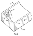
- Figure 1 is a perspective top rear view of a scanner with an embodiment of adapter for scanning transparencies.
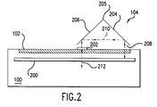
- Figure 2 is a simplified cross section end view of the scanner and adapter of figure 1.
- Figure 3 is a simplified cross section side view of an embodiment of a scanner as in figure 1 and the adapter of figure 1.
- Figure 4A is a simplified top view of the scanner embodiment of figure 3 and the adapter of figure 1.
- Figure 4B is a simplified top view of an alternative embodiment of a scanner as in figure 1 and the adapter of figure 1.
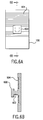
- Figure 5A is a rear plane view of the adapter of figure 1 with the angle adjuster removed.
- Figure 5B is a cross section view through the rear wall of the adapter of figure 5A.
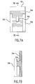
- Figure 6A is a front view of one embodiment of the angle adjuster of figure 1.
- Figure 6B is a cross section view through the angle adjuster of figure 6A.
- Figure 7A is a front view of a second embodiment of the angle adjuster of figure 1.
- Figure 7B is a cross section view through the angle adjuster of figure 7B.
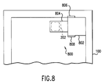
- Figure 8 is a top view of an alternative embodiment of adapter.
- Figure 1 is a perspective view of a scanner 100.
- the scanner 100 has a transparent platen 102. on which opaque documents or photographs may be placed face down for scanning.
- An adapter 104 is placed onto or near the surface of the platen.
- An image transparency for example a 35 mm positive slide or a strip of film with negative images, is placed on the platen under the adapter 104, as will be discussed below and illustrated in other figures.
- an angle adjuster 106 and an offset 108 such that part of the adapter 104 may be substantially wider than the transparent image to be scanned.
- FIG. 2 is a simplified cross-section end view of the document scanner 100 and transparency adapter 104 of figure 1.
- the document scanner 100 includes an internal lamp 200. Also illustrated is a image transparency 202.
- the transparency adapter 104 comprises two reflective surfaces (204, 206) that receive light from the lamp 200 within the scanner and re-direct the light through the transparency 202 and back into the scanner at a particular required angle.
- Dashed lines 208, 210, and 212 depict segments of a ray of light starting within the scanner from the lamp 200, reflecting off surface 204, then off surface 206, passing through the transparency 202 and then reentering the scanner 100.
- Figure 3 is a simplified cross-section side view of the document scanner and transparency adapter of figure 1.
- a scan line 300 on the top surface of the platen 102 is defined by optics (not illustrated) within the scanner.
- the required optical path with the scanner is depicted as being controlled by a field stop 302 (not illustrated in figures 1 and 2) which requires light to enter the scanner optics at a particular angle and position.
- a field stop may or may not be physically present, but in general, every scanner has some effective scan line on the image to be scanned and some effective angle for the light from the scan line entering the scanner optics.
- the scan line is defined on the top surface of the platen.
- a scanner may also include internal mirrors (not illustrated) for folding an optical path and a lens system (not illustrated). Tracing backwards along light rays 212, 210, and 208, reflective surface 204 effectively receives light along an illumination line 304, which is also defined on the top surface of the platen. Note that for reflective images, the scan line and the illumination line may be identical. That is, due to specular reflection, some light at the scan line is directly reflected at the proper angle to be received by the scanner optics. However, for the transparency adapter, an effective illumination line 304 is offset from the scan line. The intersection (205) of the reflective planes (figure 2, 204, 206) is at an angle ⁇ relative to the plane of the platen 102.
- angle ⁇ is determined by the offset between the scan line 300 and the effective illumination line 304.
- angle ⁇ and the offset between the scan line and the illumination line, are exaggerated to facilitate illustration.
- angle ⁇ is adjustable by use of angle adjuster 106.
- Figure 4A is a simplified top view of the document scanner of figure 3 and the transparency adapter of figure 1. Note in figure 4A that as a result of the angle ⁇ (figure 3), light ray segment 210 has a directional component parallel to the centerline 400 of the scanner. The directional component of segment 210 parallel to the centerline 400 provides an illumination offset required by the effective offset between the lamp 200 and the scan line 300.
- the image transparency 202 is placed near the centerline 400 of the platen 104.
- light rays from the scan line may also be required to converge toward the center line of the scanner to a small sensor array.
- a lens may be required within the adapter. Placing the image transparency near the centerline of the platen, instead of near a side edge of the platen, eliminates the need for a lens in the adapter for many scanners.
- the lamp 200 and scan line 300 move past the image transparency 202 along direction 306 (figure 3), scanning one line at a time.
- the scan line leads the lamp.
- the scan line may trail the lamp.
- the scan line 402 trails the lamp 200.
- the angle ⁇ (figure 3) remains the same, and the adapter 104 is simply rotated 180 degrees and piaced onto the opposite side of the platen (figure 4B) to provide an offset in light segment 404 (figure 4B) parallel to the centerline 400.
- the adapter 104 is made approximately the same width as the image transparency 202, when the scan line first reaches the leading edge of the image the lamp may still be outside the adapter.
- the adapter 104 is made approximately the same width as the image transparency 202. when the scan line is at the trailing edge of the image (as defined by scanning direction 30 6 in figure 3), the lamp 200 may have passed beyond the adapter.
- the reflecting surface that first receives light from the lamp is made wider than the reflecting surface that directs light through the image transparency (reflecting surface 206).
- the location of the image transparency is then offset so that in the case of the scan line leading the lamp (figures 3 and 4A), the image is placed so that when the scan line first reaches the leading edge of the image the lamp is under the adapter.
- the adapter is simply rotated 180 degrees and placed onto the opposite side of the platen, resulting in an image placement so that when the scan line reaches the trailing edge of the image, the lamp is still under the scanner.
- the entire adapter may be made as wide as the reflecting surface 204. with suitable locating features for the image transparency.
- Figure 5A shows the rear (when positioned as in figures 1, 3 and 4A) face of the adapter 104 with the angle adjuster 106 removed.
- the rear wall of the adapter includes a notch 500 with a ratchet pattern 502 formed on the rear face, on both sides of the notch.
- Figure 5B provides additional detail for the ratchet pattern 502.
- Figure 6B shows the face of the angle adjuster 106 that presses against the surface of the adapter shown in figure 5A.
- the angle adjuster 106 has a flange 600 on a post 602 so that the post 602 may be inserted into the slot 500 (figure 5A), and the flange 600 holds the angle adjuster securely against the adapter.
- Ratchet patterns 604 on the angie adjuster 106 mate with the ratchet patterns 502 on the adapter (figure 5A) so that the adjuster 106 may be easily moved upward (post 602 may easily move further into the slot 500) but the ratchet patterns will not allow the adapter to slip down unless the ratchet patterns are forced apart.
- the angle adjuster has a post 702 without a flange, and the adjuster has fingers 700 that slip behind the rear wall of the adapter for holding the angle adjuster to the adapter.
- Ratchet patterns 704 mate with ratchet patterns 502 on the adapter, thereby permitting easy attachment of the adjuster to the adapter but requiring the ratchet patterns to be forced apart to enable removal of the adjuster.
- an adapter 800 has a first reflective surface 802 receiving light, and a second reflective surface 804 that directs light through a transparent image 202. Reflective surface 802 extends beyond reflective surface 804 in both leading and trailing scanning directions to accommodate a lamp leading the scan line or a lamp trailing the scan line.
- the adapter 800 has two angle adjusters 806 and 808 so that either the leading edge or the trailing edge can be lifted.
- the resulting adapter can accommodate a lamp leading the scan line, a lamp trailing the scan line, adjustable angle ⁇ (figure 3), and is always placed with one particular adapter corner positioned at one particular platen corner.
- adapters 104 and 800 exhibit three important improvements, namely:
- adapter 104 can be used with a variety of different scanners, with different illumination line to scan line spacings, and different spatial ordering of the lamp relative to the scan line.
Landscapes
- Engineering & Computer Science (AREA)
- Multimedia (AREA)
- Signal Processing (AREA)
- Facsimile Scanning Arrangements (AREA)
Applications Claiming Priority (2)
| Application Number | Priority Date | Filing Date | Title |
|---|---|---|---|
| US09/127,454 US6018161A (en) | 1998-07-31 | 1998-07-31 | Adjustable adapter for scanning transparencies with a reflective document scanner |
| US127454 | 1998-07-31 |
Publications (2)
| Publication Number | Publication Date |
|---|---|
| EP0977421A2 true EP0977421A2 (de) | 2000-02-02 |
| EP0977421A3 EP0977421A3 (de) | 2001-01-17 |
Family
ID=22430206
Family Applications (1)
| Application Number | Title | Priority Date | Filing Date |
|---|---|---|---|
| EP99305519A Withdrawn EP0977421A3 (de) | 1998-07-31 | 1999-07-12 | Adapter für die Abtastung von Transparentfilmen mit einem reflektierenden Dokumentabtaster |
Country Status (2)
| Country | Link |
|---|---|
| US (1) | US6018161A (de) |
| EP (1) | EP0977421A3 (de) |
Cited By (2)
| Publication number | Priority date | Publication date | Assignee | Title |
|---|---|---|---|---|
| FR2862833A1 (fr) * | 2003-11-26 | 2005-05-27 | Hewlett Packard Development Co | Adaptateur pour supports transparents et ses procedes d'utilisation |
| US7529000B2 (en) * | 2004-01-21 | 2009-05-05 | Canon Kabushiki Kaisha | Image reading apparatus and image printing apparatus using the same |
Families Citing this family (8)
| Publication number | Priority date | Publication date | Assignee | Title |
|---|---|---|---|---|
| US6639697B1 (en) * | 2000-01-06 | 2003-10-28 | Hewlett-Packard Development Company, L.P. | Automatic slide feeder for use with reflective optical scanner device |
| US20030063333A1 (en) * | 2001-10-03 | 2003-04-03 | Boll David W. | Flatbed scanner with apparatus for scanning light transmissive objects |
| US7310172B2 (en) * | 2002-05-30 | 2007-12-18 | Hewlett-Packard Development Company, L.P. | Adapter for viewing and scanning images residing on transparent media |
| US7142335B2 (en) * | 2002-07-22 | 2006-11-28 | Eastman Kodak Company | Method and apparatus for transparency scanning with a duplex reflective scanner |
| US8547603B2 (en) * | 2003-11-03 | 2013-10-01 | Hewlett-Packard Development Company, L.P. | Transparency imaging systems and methods |
| US20070188833A1 (en) * | 2006-02-16 | 2007-08-16 | Pacific Alchemy Inc. | Passive transparent media adapter |
| US20090073510A1 (en) * | 2006-02-16 | 2009-03-19 | Kurt Eugene Spears | Passive Transparent Media Adapter |
| US20070291329A1 (en) * | 2006-06-14 | 2007-12-20 | Kurt Eugene Spears | Optical Transparent Media Adapter |
Family Cites Families (3)
| Publication number | Priority date | Publication date | Assignee | Title |
|---|---|---|---|---|
| US5140443A (en) * | 1989-07-25 | 1992-08-18 | Victor Company Of Japan, Ltd. | Image scanning apparatus |
| JP3707810B2 (ja) * | 1993-08-26 | 2005-10-19 | ヒューレット・パッカード・カンパニー | スキャナ用アダプタ |
| WO1999037086A1 (es) * | 1998-01-17 | 1999-07-22 | Promonor Sexta Inversiones, S.L. | Adaptador de diapositivas y negativos para escaneres planos |
-
1998
- 1998-07-31 US US09/127,454 patent/US6018161A/en not_active Expired - Fee Related
-
1999
- 1999-07-12 EP EP99305519A patent/EP0977421A3/de not_active Withdrawn
Cited By (3)
| Publication number | Priority date | Publication date | Assignee | Title |
|---|---|---|---|---|
| FR2862833A1 (fr) * | 2003-11-26 | 2005-05-27 | Hewlett Packard Development Co | Adaptateur pour supports transparents et ses procedes d'utilisation |
| US7433092B2 (en) | 2003-11-26 | 2008-10-07 | Hewlett-Packard Development Company, L.P. | Transparency media adapter and methods of use thereof |
| US7529000B2 (en) * | 2004-01-21 | 2009-05-05 | Canon Kabushiki Kaisha | Image reading apparatus and image printing apparatus using the same |
Also Published As
| Publication number | Publication date |
|---|---|
| US6018161A (en) | 2000-01-25 |
| EP0977421A3 (de) | 2001-01-17 |
Similar Documents
| Publication | Publication Date | Title |
|---|---|---|
| JP3707810B2 (ja) | スキャナ用アダプタ | |
| JP3897852B2 (ja) | 媒体表面形状データ取得方法 | |
| JP2980386B2 (ja) | ミラーに取りつけられる遮光アパーチャを備えた光学スキャナ | |
| US6018161A (en) | Adjustable adapter for scanning transparencies with a reflective document scanner | |
| JPH04280569A (ja) | ポータブルコピー機のためのプラテンとそれを使用した複写装置 | |
| KR100576806B1 (ko) | 광학식 물체 캡쳐링 장치 | |
| JPS62112144A (ja) | インスタント・カメラのための複写用付属装置 | |
| JPH0951405A (ja) | 画像読取装置 | |
| US6952293B2 (en) | Document backing surface for show-through and artifact reduction | |
| JPH04128707A (ja) | イメージスキャナ | |
| WO2005038705A2 (en) | Fast scanner with rotatable mirror and image processing system | |
| JPH01190071A (ja) | 撮像プリント装置 | |
| JP3638575B2 (ja) | 画像記録装置 | |
| JP3443353B2 (ja) | 原稿読取り装置の調整装置および方法 | |
| JP2000066134A (ja) | 結像装置、該結像装置を用いる画像読取装置及び光書込装置 | |
| JP2689247B2 (ja) | 画像読取装置 | |
| JP3125522B2 (ja) | 画像読取装置 | |
| JPH11328298A (ja) | コードリーダ | |
| JP2985240B2 (ja) | 原稿読取り装置 | |
| JPS62224160A (ja) | 原稿縮小読取り装置 | |
| JP2689838B2 (ja) | 写真焼付装置における光源部の反射部材 | |
| JP3909875B2 (ja) | 原稿照明装置 | |
| JPS62222769A (ja) | 原稿縮小読取り装置 | |
| JPH0514602A (ja) | 画像読取装置 | |
| JPH09205523A (ja) | カラー画像読み取り装置 |
Legal Events
| Date | Code | Title | Description |
|---|---|---|---|
| PUAI | Public reference made under article 153(3) epc to a published international application that has entered the european phase |
Free format text: ORIGINAL CODE: 0009012 |
|
| AK | Designated contracting states |
Kind code of ref document: A2 Designated state(s): DE FR GB |
|
| AX | Request for extension of the european patent |
Free format text: AL;LT;LV;MK;RO;SI |
|
| PUAL | Search report despatched |
Free format text: ORIGINAL CODE: 0009013 |
|
| AK | Designated contracting states |
Kind code of ref document: A3 Designated state(s): AT BE CH CY DE DK ES FI FR GB GR IE IT LI LU MC NL PT SE |
|
| AX | Request for extension of the european patent |
Free format text: AL;LT;LV;MK;RO;SI |
|
| RAP1 | Party data changed (applicant data changed or rights of an application transferred) |
Owner name: HEWLETT-PACKARD COMPANY, A DELAWARE CORPORATION |
|
| 17P | Request for examination filed |
Effective date: 20010507 |
|
| AKX | Designation fees paid |
Free format text: DE FR GB |
|
| 17Q | First examination report despatched |
Effective date: 20040414 |
|
| STAA | Information on the status of an ep patent application or granted ep patent |
Free format text: STATUS: THE APPLICATION IS DEEMED TO BE WITHDRAWN |
|
| 18D | Application deemed to be withdrawn |
Effective date: 20060217 |