EP0977224A2 - Procédé pour la fabrication d'un interupteur éléctrique - Google Patents
Procédé pour la fabrication d'un interupteur éléctrique Download PDFInfo
- Publication number
- EP0977224A2 EP0977224A2 EP99114837A EP99114837A EP0977224A2 EP 0977224 A2 EP0977224 A2 EP 0977224A2 EP 99114837 A EP99114837 A EP 99114837A EP 99114837 A EP99114837 A EP 99114837A EP 0977224 A2 EP0977224 A2 EP 0977224A2
- Authority
- EP
- European Patent Office
- Prior art keywords
- connections
- base
- switch
- switching device
- contact
- Prior art date
- Legal status (The legal status is an assumption and is not a legal conclusion. Google has not performed a legal analysis and makes no representation as to the accuracy of the status listed.)
- Withdrawn
Links
Images

Classifications
-
- B—PERFORMING OPERATIONS; TRANSPORTING
- B29—WORKING OF PLASTICS; WORKING OF SUBSTANCES IN A PLASTIC STATE IN GENERAL
- B29C—SHAPING OR JOINING OF PLASTICS; SHAPING OF MATERIAL IN A PLASTIC STATE, NOT OTHERWISE PROVIDED FOR; AFTER-TREATMENT OF THE SHAPED PRODUCTS, e.g. REPAIRING
- B29C45/00—Injection moulding, i.e. forcing the required volume of moulding material through a nozzle into a closed mould; Apparatus therefor
- B29C45/14—Injection moulding, i.e. forcing the required volume of moulding material through a nozzle into a closed mould; Apparatus therefor incorporating preformed parts or layers, e.g. injection moulding around inserts or for coating articles
- B29C45/1418—Injection moulding, i.e. forcing the required volume of moulding material through a nozzle into a closed mould; Apparatus therefor incorporating preformed parts or layers, e.g. injection moulding around inserts or for coating articles the inserts being deformed or preformed, e.g. by the injection pressure
- B29C45/14221—Injection moulding, i.e. forcing the required volume of moulding material through a nozzle into a closed mould; Apparatus therefor incorporating preformed parts or layers, e.g. injection moulding around inserts or for coating articles the inserts being deformed or preformed, e.g. by the injection pressure by tools, e.g. cutting means
-
- B—PERFORMING OPERATIONS; TRANSPORTING
- B29—WORKING OF PLASTICS; WORKING OF SUBSTANCES IN A PLASTIC STATE IN GENERAL
- B29C—SHAPING OR JOINING OF PLASTICS; SHAPING OF MATERIAL IN A PLASTIC STATE, NOT OTHERWISE PROVIDED FOR; AFTER-TREATMENT OF THE SHAPED PRODUCTS, e.g. REPAIRING
- B29C45/00—Injection moulding, i.e. forcing the required volume of moulding material through a nozzle into a closed mould; Apparatus therefor
- B29C45/14—Injection moulding, i.e. forcing the required volume of moulding material through a nozzle into a closed mould; Apparatus therefor incorporating preformed parts or layers, e.g. injection moulding around inserts or for coating articles
- B29C45/14639—Injection moulding, i.e. forcing the required volume of moulding material through a nozzle into a closed mould; Apparatus therefor incorporating preformed parts or layers, e.g. injection moulding around inserts or for coating articles for obtaining an insulating effect, e.g. for electrical components
-
- H—ELECTRICITY
- H01—ELECTRIC ELEMENTS
- H01H—ELECTRIC SWITCHES; RELAYS; SELECTORS; EMERGENCY PROTECTIVE DEVICES
- H01H11/00—Apparatus or processes specially adapted for the manufacture of electric switches
- H01H11/0056—Apparatus or processes specially adapted for the manufacture of electric switches comprising a successive blank-stamping, insert-moulding and severing operation
-
- H—ELECTRICITY
- H01—ELECTRIC ELEMENTS
- H01H—ELECTRIC SWITCHES; RELAYS; SELECTORS; EMERGENCY PROTECTIVE DEVICES
- H01H37/00—Thermally-actuated switches
- H01H37/02—Details
- H01H37/12—Means for adjustment of "on" or "off" operating temperature
- H01H37/14—Means for adjustment of "on" or "off" operating temperature by anticipatory electric heater
-
- H—ELECTRICITY
- H01—ELECTRIC ELEMENTS
- H01H—ELECTRIC SWITCHES; RELAYS; SELECTORS; EMERGENCY PROTECTIVE DEVICES
- H01H61/00—Electrothermal relays
- H01H61/02—Electrothermal relays wherein the thermally-sensitive member is heated indirectly, e.g. resistively, inductively
-
- H—ELECTRICITY
- H01—ELECTRIC ELEMENTS
- H01H—ELECTRIC SWITCHES; RELAYS; SELECTORS; EMERGENCY PROTECTIVE DEVICES
- H01H3/00—Mechanisms for operating contacts
- H01H3/02—Operating parts, i.e. for operating driving mechanism by a mechanical force external to the switch
- H01H3/08—Turn knobs
- H01H3/10—Means for securing to shaft of driving mechanism
-
- H—ELECTRICITY
- H01—ELECTRIC ELEMENTS
- H01H—ELECTRIC SWITCHES; RELAYS; SELECTORS; EMERGENCY PROTECTIVE DEVICES
- H01H3/00—Mechanisms for operating contacts
- H01H3/02—Operating parts, i.e. for operating driving mechanism by a mechanical force external to the switch
- H01H3/20—Operating parts, i.e. for operating driving mechanism by a mechanical force external to the switch wherein an auxiliary movement thereof, or of an attachment thereto, is necessary before the main movement is possible or effective, e.g. for unlatching, for coupling
-
- H—ELECTRICITY
- H01—ELECTRIC ELEMENTS
- H01H—ELECTRIC SWITCHES; RELAYS; SELECTORS; EMERGENCY PROTECTIVE DEVICES
- H01H37/00—Thermally-actuated switches
- H01H37/02—Details
- H01H37/04—Bases; Housings; Mountings
-
- H—ELECTRICITY
- H01—ELECTRIC ELEMENTS
- H01H—ELECTRIC SWITCHES; RELAYS; SELECTORS; EMERGENCY PROTECTIVE DEVICES
- H01H37/00—Thermally-actuated switches
- H01H37/02—Details
- H01H37/12—Means for adjustment of "on" or "off" operating temperature
-
- H—ELECTRICITY
- H01—ELECTRIC ELEMENTS
- H01H—ELECTRIC SWITCHES; RELAYS; SELECTORS; EMERGENCY PROTECTIVE DEVICES
- H01H37/00—Thermally-actuated switches
- H01H37/02—Details
- H01H37/32—Thermally-sensitive members
- H01H37/52—Thermally-sensitive members actuated due to deflection of bimetallic element
- H01H37/54—Thermally-sensitive members actuated due to deflection of bimetallic element wherein the bimetallic element is inherently snap acting
-
- H—ELECTRICITY
- H01—ELECTRIC ELEMENTS
- H01H—ELECTRIC SWITCHES; RELAYS; SELECTORS; EMERGENCY PROTECTIVE DEVICES
- H01H89/00—Combinations of two or more different basic types of electric switches, relays, selectors and emergency protective devices, not covered by any single one of the other main groups of this subclass
- H01H89/04—Combination of a thermally actuated switch with a manually operated switch
Definitions
- the invention relates to a method for producing a electrical switching device, in particular a clocking Power control unit, with a switch with switch contact and mating contact and a switchgear base, the connections contains.
- Such switching devices are for example from the DE 26 25 716 known.
- Connections in the form of metal flags are usually in the geometry of the metal flag corresponding slots are inserted in the switchgear base and by splitting paragraphs in the area of the inside of the switching device base are arranged, in the manner of a Caulking set.
- the expanding material of the Metal flag presses against the material to hold on the switchgear base, which is preferably made of plastic.
- Connections and connections between the Connections or other facilities can be advantageous worked out of a flat material and in a subsequent one Manufacturing section as a continuous circuit board with the connections between the connections in a device be introduced in the individual sections by Bending and / or folding brought out of the plane of the board become. Connections can preferably still to a holding frame or the like consist. Then the board can be in one Form in which all connections are interconnected are in a mold or a tool for producing the Switchgear base made of plastically deformable during production Material are introduced. Some parts of the board, preferably connections, can limit the shape of the tool form. Parts of the board can run such that they completely at least in sections of the material be enclosed.
- the switchgear base After making the switchgear base can at least in a further manufacturing process severed a connection between at least two connections quasi as a separation of sections or Connections of the board after the switchgear base has been manufactured.
- Such a method has the advantage that the Connections firmly, permanently and mechanically resilient in the Switchgear base are held.
- Another advantage is that only one assembly in the form of contiguous board must be handled instead of several individual connecting lugs and / or connections.
- the connections can preferably be separated by stamping , it is possible to separate by the Punch through the material of the switchgear base.
- the die cuts can be in a very limited area take place because the connections are preferably relatively narrow are executed.
- An adverse mechanical weakening of the Switching device base is not closed by such punchings fear. It is possible to connect the switchgear base to be performed in such a way that it has to be punched through anyway or areas of the switchgear base to be broken through happen. For example, Bearing openings for parts or functional units of the switching device his.
- At least one connection or contact path of the board advantageously remains uncut and leads from a connection to the switch or a contact option of the switch.
- a preferred manufacturing method for the switchgear base is an injection molding process. It can be electrical and / or thermally insulating plastic can be used, preferably a thermoplastic. One can in one spraying process or several boards are overmolded at the same time.
- the flat material of the board can be used as an endless belt or Continuous material are fed, preferably to a Punching device in which the connections and connections be punched out of the material can. After working out the connections and connections the board can be separated from the continuous material become.
- the continuous material preferably has for reduction from blending to a width corresponding to a dimension of the Board corresponds.
- connection edges can, especially in the area afterwards in the switchgear base, irregularly designed or provided with recesses, for example with a toothing. That way is a secure hold of the cast or injected connections guaranteed in the switchgear base.
- an electrical switching device created or are produced which has a switching device base, the Contains connections to the outside and at least one switch which carries at least one switching contact and at least has a counter contact.
- the contacts can be with connectors be connected and at least one connection from one Connection to the switch can at least in sections be completely surrounded by the switchgear base. Prefers this connection is cast into the switchgear base.
- the switchgear base can be a housing wall of the switchgear form, preferably a rear wall of a substantially flat housing of the switching device. At least partially can Side walls of the housing molded onto the switchgear base his.
- connection lugs can be used as Plug contacts or plug connection lugs on a back survive the switchgear base, for example with a Height from approx. 5 mm to 10 mm, also as soldering tags.
- On Flat material from which the connections are preferably made are between 0.2 mm and 2 mm thick.
- connections preferably protrude at least partially an inner side of the switchgear base in front, in particular run through the switchgear base. With one side they can advantageously at least partially Protrusions lie on the inside and through them be supported or support them.
- connection separators or the like On the back and / or the inside you can choose between at least two connections separators or the like. get lost that are preferably formed on the switchgear base or with this are firmly connected.
- the webs can be roughly the height of the connections, preferably projecting above them.
- a thickness or thickness of the webs in the Considered a range between 0.5 mm and 5 mm, particularly advantageous approx. 1 mm.
- At least three connections can be made on the back in one Be arranged in a row, preferably several rows available.
- the rows can run parallel to each other.
- the connections are preferably flat and at least two connections point along a line.
- Several Lines can have at least two connections each be formed, the lines preferably running parallel.
- the connections can be arranged in groups that from at least two interconnected connections can exist. This enables looping through to the Connections.
- a connection of the connections with each other runs at least partially within the switchgear base by the number of exposed, electrically conductive Reduce parts.
- a central area of the switchgear base is preferred free of connections or connections, whereby he for example as a holder for an adjustment device of the switching device can be trained.
- the recording can at least partly round, especially with several concentric ones Gradations formed as a recess in the switchgear base his.
- the receptacle on the inside is preferred arranged of the switching device base, wherein the switching device base can protrude in a pot shape over the back sufficient space for several gradations, possibly more Facilities to have available.
- At least one connector can be used as a contact on the inside of the switchgear base protrude, preferably a Wearing contact head, which consist of special contact material can and is soldered or welded or for example is produced by embossing as a bulge on the connection.
- At least two connections preferably each have one Contact head at the same height above the inside. At least two contacts are advantageous for a common one Switching direction in the same direction.
- the switch carried by the switchgear base is advantageous a snap switch, in particular a has bistable snap spring with a switch contact head. Tripping can be triggered by a thermomechanical switching device, preferably a thermal bimetal with heating, can be triggered. Via an adjustment device, for example a control axis with a handle, can influence the Snap switch are done. A way of influencing is a change in the position of the snap switch in the Relationship to the triggering switching element, whereby the Switching behavior of the switch or a switching interval duration can be changed.
- the adjustment can be advantageous further switching devices are triggered directly, for example simple contact switches.
- the inside of the switching device base advantageously has a Storage or admission for another switching device on, preferably as a longitudinal guide with at least one Longitudinal groove is formed.
- This second switching device is preferably one by the adjustment device against one Spring device operated slide switch. He can out a molded body displaceable in the longitudinal guide, the at least one switching arm provided with a contact head wearing.
- a mating contact can come from the switchgear base projecting connections.
- the Shaped body two switching arms or a continuous switching arm with contact heads at the ends, which are attached to each a mating contact electrically connect them.
- both larger electrical outputs are switched, for example additional heaters at one Switchgear as a circuit breaker for an electric cooker, or Signals that are only a change of state to a controller give. If there are several switching arms in the direction of displacement arranged one behind the other, can be simultaneously or several switching operations are triggered in succession.
- a Triggering the slide switch can, similar to an influence the snap switch, via at least one on the Control axis seated cam roller are triggered.
- Both the Snap switch as well as the slide switch can with Protrusions or the like abut one cam roller each.
- the longitudinal guide can preferably be limited by one portion of the circuit board protruding from the inside, from which the connections are made, exist. You can one Abutment and / or a mounting for a spring device of the slide switch, in particular one bent tab at one end for fastening the spring device is provided.
- a third switching device be, especially as struck or welded to it metallic spring arm with a contact head on one The End.
- the mating contact head is preferably on another attached protruding connection on the switchgear base.
- the two contact heads can either be spaced or close the contact, and by the Adjustment device can be triggered.
- a trigger can ever after setting up this switch, opening or closing the Be in contact.
- the adjustment device can switch operations of the Slide switch and the third switching device simultaneously or in different positions of the adjustment device respectively.
- an electrical switching device with a Switchgear socket and connections are created a snap switch with at least one snap spring has, which carries at least one switch contact head.
- the snap switch is through a thermomechanical switching element triggerable, with its thermal influence a heater with a metallic support for at least one heating resistor is provided.
- the thermomechanical Switching element is preferably a thermal bimetal, the layer with the larger one being particularly preferred Expansion coefficient to the carrier or the heating resistor points out.
- the carrier consists of Flat material, in particular a plate with a Thickness is between 0.1 mm and 4 mm, for example approx. 1 mm. It can have a rectangular shape.
- the carrier advantageously has an electrically insulating one Insulation layer between at least one surface and the at least one heating resistor. It can be unsolvable be applied to a top of the carrier and this in cover essential.
- An insulation layer can, for example applied by a thick film process it is preferably glass-like or made of glass or ceramic. Alternatively, insulating foils or the like are possible, for example. out high temperature resistant plastic.
- a contact field can at least partially directly on the Insulation layer applied and in one area Heating resistor for electrical contact overlap or overlap with this.
- Another, preferably second, The contact field can rest directly on the carrier material and contact the carrier.
- cover the insulation layer preferably only partially a surface of the carrier, so that the contact field directly in the free section can rest on the wearer.
- a third contact field is also possible, that, for example, a kind of center tap of the Heating resistor allows. It is preferably on the Insulation layer and protrudes laterally under the heating resistor in front.
- the surface of the carrier can at least partially consist of one steel suitable for thick-film processes, a so-called Thick-film steel. More on this is in the EP-A 885 579.
- the carrier can be made entirely a thick-layer steel.
- the carrier of several layers that cannot be detached, in particular from at least one thick-layer steel layer as Outside for the heater and at least one copper-containing layer.
- a layer structure is preferred of the carrier symmetrical to its median plane and particularly preferably has a core layer made of copper and Outer layers of thick-layer steel. This has the advantage that a bimetal effect of the carrier is avoided and the copper core is substantially enclosed.
- the Middle layer of copper should be thicker than the outer layers, in particular two to twenty times as thick, preferred about four times as thick.
- Such a material is e.g. by Plating from individual sheets or the like. can be produced on a large scale, the individual carrier plates then only must be cut out and separated.
- the carrier can be held on the switching element, for example by contact welding.
- the switching element is preferred metallic and electrically conductive, being an electrical Can form a connection for the heating device.
- the Carrier and the switching element can be in the area of their Touch the surface of the connection, both of which at least partially are flat and level.
- the switching element from about the middle third of the carrier or Heating resistor spaced therefrom preferably runs at a small and approximately the same distance from it and protrudes a long way over the beam.
- the switching element is preferably elongated and lies with a free end on the snap spring, in particular on one free end of the snap spring.
- the end of the switching device can be hook-like or the like be turned, being advantageous in this hook-shaped turn a recess in the longitudinal direction of the switching element.
- an adjustment device for changing the Distance between switching element and snap spring can be in Region of the free end of the switching element may be provided, for example in the hook-shaped turn.
- An adjustment can be done by a rotary movement. This is advantageously a pin provided with a circumferential and steadily increasing diameter widening in the bend is stored and with the diameter extension on the free end of the snap spring rests. Turning is one The distance can be changed. If the axis of rotation and / or the pin axis perpendicular to the direction of movement of the switching element has an adjustment in the axial direction force occurring no adjustment of the snap spring Sequence and precise adjustment is possible.
- the pin preferably has tool engagement surfaces on a section on. The diameter expansion is preferred in the elongated recess. If the turn for the Pin the more expanding layer of the switching element or thermobimetal radially on the outside, closes the Bend when heated and clamps the adjustment pin, see above that rotation of the same can be avoided.
- an adjustment device can engage the carrier, in particular on the side facing away from the switching element Side and / or on the heating device. Through them the Position of the carrier and / or the snap spring relative to a storage of the snap spring with which the carrier over the switching element attached to the snap spring is connected, be determined.
- the adjustment device be at least partially electrically conductive, preferably metallic, advantageously an electrical Connection for the heating resistor forms.
- a possibility is a metal screw mounted in the switchgear base, which points in the direction of movement of the switching element and at a contact or contact field of the heating resistor is present.
- the bearing of the screw can be connected to the switching device may be connected, in particular in one piece. For This connection can at least improve insulation partially completely within the switchgear base run, for example injected therein during the manufacturing process become. So it is possible to have a connecting lug or the like. somewhere other than the one connection for the Heating device to be provided.
- the switching element can be resiliently attached to the switching device base be, preferably on one over the inside of the Switching device base-reaching section of a connection for the switching device. It is preferably under elastic tension on an adjustment device for its position. With the support for the heating resistor can be on a contact device for the heating.
- the snap spring is preferably about an elastic Carrying sheet, which with the free end of the snap spring connected to the switchgear base. With elastic tension, it is in the direction of the Switching element too pressed, for which purpose the support plate is approximately U-shaped can be bent and carries both the switching element and presses both devices towards each other.
- a grinder can be attached to the support plate a projection on an adjusting device elastic is applied and in this way the position of the snap spring determines relative to the adjusting device. He can at the from the side facing away from the snap spring, preferably in the Near the fastening of the carrying plate to the switchgear base, be attached.
- the adjusting device preferably has a control axis with at least one cam roller, the radius of the Cam roller increases at least in sections. Go berserk the control axis together with the cam roller can change the position of the Snap spring can be changed, for example the distance of the free end to be changed to the switching element.
- the snap spring is preferably a bistable three-point leaf spring executed, in particular in one piece.
- She points preferably two hairpin-shaped legs on at least one end, preferably both, connected together are, with a connected end on an extension of the Switch contact head carries.
- One of one end, especially the one with the switch contact head, outgoing spring tongue run and on an abutment be supported.
- the spring tongue is usually opposite the thighs under tension and stores part of the Switching energy for the switching process.
- the grinder can be designed as a thermal bimetal and preferably the abutment for the spring tongue of the snap spring form. It is possible to use it as a compensation bimetal execute the same bending direction as the switching element. So is a compensation of one caused by external circumstances Change in the ambient temperature and thus one Shape change of the switching bimetallic possible in a wide Ambient temperature range to an exact switching behavior guarantee.
- a switching device in particular according to one described above Manufacturing process has been made, can Switchgear base, at least one switch, one on the Switching device base mounted adjustment device for influencing the switching behavior of the switch and a handle have together with operating areas for a user.
- Such a blocking device can cause an unwanted or accidental adjustment or switching on one that can be actuated by the switching device Avoid setup.
- the provision of an elastic Resistance device can allow the Blocking in certain positions or any position automatically activated to increase inherent safety.
- Such blocking devices are, for example, as Child locks in use, but only solve their task incomplete.
- the Adjustment device a control axis and the adjustment movement be a rotation about this axis, the axis being advantageous carries at least one cam roller or the like or at least is rotationally connected to it.
- the cam roller can one have varying or increasing radius in some areas, which increase or decrease to different degrees can.
- the control axis is preferably with one end or End area stored in the switchgear base and points to the the other end of the handle.
- the handle can, preferably also the control axis, in the longitudinal direction of the control axis at least partially compared to the switching device and / or be movable with respect to the cam roller. This enables the blocking device in the longitudinal direction of the control axis designed to be detachable and / or activatable.
- a solution to the Blocking by pressing and / or turning the handle regarded as particularly advantageous.
- a suspension may be provided, in particular as the spring surrounding the control axis with constant Diameter.
- the spring can at least partially circumferential projection of the control axis and a bottom one Apply recess in the switchgear base.
- the feather is advantageously made of metal, for example with a spiral spring few turns.
- Blocking device between control axis and switchgear base formed and arranged in the area of the switchgear base can include storage. It is possible to move the control axis in the area of your Execute storage out of round, for example with a preferably flattened protrusion or section of itself over the cross section of the preferably round control axis raises. Appropriate to this, the storage points to the non-circular Corresponding recess in a breakthrough section the switchgear base.
- a diameter expansion of the Control axis as a non-circular projection can be 1.5 times to 4 times of the radius of the control axis, preferably that about 2.5 times.
- the diameter expansion can be a Length between 1 mm and 10 mm, in particular about 3 mm, at the Control axis extend to provide sufficient mechanical strength to grant.
- the blocking device on a cover between the handle and the switchgear base to let attack, partly for the handle can be included.
- the cover is preferred formed as a front panel of an electrical device or the like whose back is attached to the switching device, the Control axis runs through an opening in the panel and the Handle carries.
- the blocking device can have at least one recess and at least one corresponding and when blocking in it engaging protrusion by movement the handle in the longitudinal direction of the control axis in or out of Intervention can be brought.
- Such movement is advantageous a movement of the handle towards the cover.
- At least a recess is in the cover and at least one Projection is at one through the opening of the cover protruding radially inner portion of the handle educated. If the handle is pressed against the cover, the projection on the handle moves out of the recess in the Cover off and the handle can be rotated freely.
- the handle preferably has one fastened to the control axis Inner gag part and an outer gag part attached to it with operating areas.
- the gag outer part can be used as Ring essentially enclose or surround the inner part and with respect to this rotatable and axially against an elastic Resistance can be moved.
- Between the two Corresponding locking means can be arranged in parts, those in the normal state, preferably by resistance automatically produced, be free of each other or can get free. By axially shifting it is then possible to engage them and circumferentially to connect positively. After that there is a transfer of Forces in the circumferential direction, i.e. adjusting forces, by the Gag outer part or the actuating surfaces on the inner part or the control axis possible.
- the latching means preferably comprise at least one recess and at least one corresponding projection, the especially in the area of the outer circumference of the inner part of the gag are designed to better absorb torques.
- At least one recess on the inner part of the gag is advantageous and at least a suitable head start on that Outside gag formed. With exactly one recess each and a projection can only be locked in one Position take place. Locking in multiple positions is by providing several recesses or projections possible.
- an additional suspension as an elastic resistance between the inner part of the gag and toggle outer part can be provided, in particular in the area the inner circumference of the outer gag part.
- a short coil spring those in a narrow circular cylindrical space runs between the inner part of the gag and the outer part of the gag sign up for this.
- Their spring constant or their resistance can be chosen larger than that of the suspension of the inner gag part opposite the switchgear base, which means that when pressed in the handle or the actuating surfaces over the gag outer part first the inner part of the toggle opposite the switchgear base can be moved, preferably to solve the Blocking device, and then the stronger resistance the additional spring device is overcome to gag and Gag outer part for actuating the control axis with each other connect to.
- the inner part of the gag can be moved axially on the control axis be stored, these at least partially laterally is flattened.
- the inner part can then be matched with a corresponding one central blind hole in which there is a spring device is to be put on.
- the control axis is included axially immovable relative to the switchgear base. By the axial displacement of the inner part of the gag relative to one Covering the base or front panel can be loosened and / or the blocking is activated.
- a switching device with a switching device base and an adjustment device for at least one switch part with one Shaped body can in particular according to one described above Manufacturing process to be made. It is on the Shaped body at least one contact carrier with at least one Switch contact head held and the switch part is in contact non-metallic elastic spring means. Such one Switch part can be used in addition to other switching devices be provided on a switching device.
- non-metallic spring means that there is a risk of short circuits or unwanted contacts, avoided with spiral springs becomes.
- the spring means advantageously consist of plastic material, which is preferably silicone-containing, particularly preferred is made entirely of silicone.
- the material is preferred the spring means foamed, preferably by a factor of 1.2 to 10, for example by a factor of 2.
- a Foaming the plastic material is sufficient exactly definable elasticity of the spring means achieved.
- material and weight can be saved.
- the spring means with cavities and / or recesses be provided that favor elasticity.
- the spring means formed as a voluminous spring body, the length in relaxed state in the direction of adjustment of the switch part pointing less than its height or width or Diameter.
- the spring body can at least be relaxed State in the direction of adjustment of the switch part cylindrical be advantageous, it is cuboid.
- a voluminous spring body in contrast to one elongated coil spring or the like.
- a voluminous spring body the expansion transverse to the direction of force as well as the contact surfaces given a secure hold.
- elastic bodies also less sensitive to shear forces, since this is also the Subject to spring action of the material.
- the spring means are preferably on the switchgear base supported, in particular attached to it.
- the spring means offers an abutment protruding from the switchgear base on, which is held on or in the switchgear base can be embedded metal plate.
- An attachment can by bending a tab or a projection of the metal plate on or in the spring means, alternatively gluing possible.
- a fastening of the spring means is also considered to be favorable made the switch part, preferably on the molded body. Since the molded body is advantageously made of plastic the spring means preferably glued to it. Another Possibility is to form a mandrel or the like on the Shaped body on which the spring body is inserted can.
- the spring body In the relaxed state, can have a length in the range between 3 mm and 20 mm, in particular approximately 6 mm.
- a cross-sectional area in the direction of adjustment of the switch part can be between 10 mm 2 and 200 mm 2 , preferably approximately 50 mm 2 .
- the structure of the molded body can be adjusted in the direction of adjustment different sections to be divided depending on the spring travel or the compression of the spring body a different spring behavior or different Adjust spring forces.
- One way to do this can be recesses or cavities in the molded body, which results in a different cross section results.
- FIG. 1 shows a section of a flat material strip 11, from the connections in the form of plug-in terminal lugs 12 together Connections to each other are worked out. Working out can be done by punching, for example is also cutting with a laser beam or thin Materials even with high pressure water jets.
- the majority the plug-in tabs 12 is in pairs side by side arranged and interconnected, being between flags or pairs of flags connecting webs 13. Partially the connections carry contact heads 14.
- a receiving web 15 the two holes 17 for Includes an adjustment screw.
- the left section of the flat material strip 11 shows a stage after being worked out of flags 12 and connecting bridges 13.
- the right one Section shows a circuit board 16, which by appropriate Bending the connector tabs 12 and the connecting webs 13 is produced in the drawing plane.
- the receiving web 15 is set up and its end is bent over in such a way that the two holes 17 continuously one behind the other lie. It is possible to form several boards a flat material that can be related.
- plug-in connection lugs 12 already latching openings 19 and filling holes 20 attached which the slide-on plug-in shoes snap into or which ones fills the plastic material for improved grip.
- a metallic fastening tab 18 also projects from above between the connecting lugs 12 Foam block described below as suspension for switch parts be attached.
- transport holes 24, a single flag 22 with a metal plate 48 and an additional connection 45 are provided.
- FIG. 2 illustrates the oblique view of the flat material 11 from FIG. 1 shows the arrangement of the bent or installed plug-in connection lugs 12 and connecting webs 13 and the receiving web 15 and the mounting tab 18 of the Circuit board 16.
- the parts shown in broken lines are for the Later connection in the switchgear base is not necessary or annoying and are at least partially removed. Only the connecting web 13, the one of the group of Terminal lugs 12 leads to the receiving web 15 remains receive. Above all, the middle connecting web 13 remains received during the spraying process, but will be later severed.
- the rear connection of the circuit board 16 in FIG. 2 to the outer frame 21 can already in that shown in Fig. 2 Method step up to the connecting lugs 12 be cut without the cohesion of the board 16 affect.
- An advantage is that the entire board 16 in Interaction with the outer frame 21 through the connecting webs 13 is held together, and so as a structural unit can be supplied to the spraying process.
- the transport holes 24 are provided on projections, through which the flat material strip 11 in an automatic Manufacturing recorded safely and accurately can be transported.
- FIG. 3 illustrates that the plug-in connection lugs 12 and 22 both in rows and in parallel and with a common one Height out of the board 16 are formed. It is to recognize that the connecting web 13, which to the receiving web 15 leads, partly from the plane of the outer frame 21 is removed. The purpose of this special arrangement is explained below.
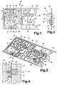
- FIG. 4 shows a section of part of the circuit board 16 in an injection molding tool 25, which consists of an upper mold half 26 and a lower tool half 27 there.
- a plug connector lug is representative of the circuit board 16 12 with a contact head 14 and an adjoining one Supernatant 29 shown.
- the flat material has a filling hole 20 which with plastic material one on the connector lug 12th molded support section 30 is filled. In the area before the upper tool half 26 runs through the contact head 14 such that it remains freely accessible.
- a part of the base 31 of the switching device base is and two dividers 32 protruding from the underside thereof shown.
- the dividers run parallel to the plug connection lugs 12 and separate them from each other or after outside. Their exact training is shown below and explained.
- the flow direction D 5 runs from top to bottom.
- flat material is used, preferably in tape form suitable width, for example on a drum 34 magazine and unrolled from it.
- On the still continuous belt are made by contact welding at a contact welding station 35 the contact heads 14 each in the right place attached on both sides. This can be done at the welding station 35 or at another station. Part of the contacts can also be made by embossing.
- the next step is to turn the flat material strip with contacts 11 in a processing station 36 first Flat material strip according to the left section of FIG. 1 worked out by punching. After working out the threaded holes in the machining station 36 formed in the bores 17, for example by tapping.
- the still coherent flat material strip 11 is from the processing station 36 to the three work steps comprehensive finishing station 37 out.
- the board 16 either still connected to the outer frame 21 or already separated from it, preferably in a coherent manner, in an overmolding system 38 introduced into an injection molding tool 25 according to FIG. 4 and accordingly at least partially with plastic encapsulated.
- the last step in the finishing station 37 takes place the necessary separation of the board 16, namely one the caps of the unwanted connecting webs 13th by punching through within the plug-in connection lugs the molded base of the appliance 31 possibly the connections to the outer frame 21, which from the Stand out, cut through.
- the work steps in the finishing station 37 is the switchgear base ready and can, for example in boxes 39, further Processing stations such as the automatic assembly machine 40 fed become.
- Several flat material strips can be used in parallel go through the same stations.
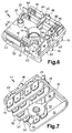
- FIG. 6 shows one for example according to the invention Manufacturing process manufactured switchgear base 41. It can be seen that on a substantially flat Base 31 structures such as the support sections 30 are attached or molded. The supernatants 29 the connections still protrude beyond the support sections 30, while the upper sections of the connector tabs 12 together of the contact heads 14 lie on the support sections. To Four contact heads arranged in the side areas can be seen 14, between which a longitudinal guide 42 for one Slide switch described below is formed. On its end on the edge of the switchgear base 41 is the fastening tab 18 provided.
- an additional connection 45 is provided, which is a good way over protrudes the base 31 and at a double right angle bent section carries a contact head 14.
- On this contact head 14 can be shown, on which Overhang 29 attached on the opposite side Switch arm with a switch contact and by actuation can be opened or closed by the control axis.
- the shift arm runs a good way above the four lower contact heads 14 so that an actuation in separate levels can be made.
- connection 45 in the illustrated embodiment not in a coherent board 16 with the other connections introduced into the injection mold 25 can either be brought into the tool separately or but have been attached to the base afterwards, for example by pressing into a preformed cutout.
- the mating contact head is close to the receptacle 44 46 provided for the device switch. This one too Connection is supported on a support section 30 of the base 41. Next to it in the area of the edge of the base a protruding holding plate 48 made of flat material is provided, to which the device switch can be attached.
- the Recognizing web 15 At the opposite end of the longitudinal guide 42 is the Recognizing web 15, the on its two long sides is essentially covered by plastic.
- the threaded one provided bores 17 are kept clear.
- On the left part of the connecting web can be seen at the rear edge of the base 41 13, from the receiving bridge 15 to the supernatant 29 and thus leads to connections.
- This connecting web 13 runs largely within the Base 31 and was not the only connecting bridge severed.
- Screw mounts 49 set or injection molded into either Screws for fastening an upper part of the switchgear housing or to attach the switchgear to, for example of a front panel of an electrical device can. Separators go from the bottom of the base 31 32, which are shown in more detail in FIG. 7.
- FIG. 7 shows the switchgear base 41 from FIG. 6 in Oblique view from below. From the base 31 are the all parallel aligned terminal lugs 12 in front. In the middle of the base floor is the pot-shaped over the rear extending receptacle 44 shown.
- the plug connection lugs 12 are arranged in two rows of four, where two successive plug-in connection lugs are connected as pairs, then comes the additional connection 45, the individual connection 22, the is connected to the holding plate 48 and a pair of Connection lugs arranged one behind the other Counter contact 46 carrying and projecting over the inside Have protrusion 29.
- the two individual plug-in connection lugs are with the outermost flags on either side of the two rows of four arranged in a row. To this One obtains the clear one which can be clearly seen in FIG. 7 and concise arrangement of the connector lugs with each same orientation. There is still enough space in the Socket 41 available, or the like for further plug connections. to provide.
- the dividers 32 run parallel to the flags entire width of the base 41.
- the middle separating web runs along the side of the pot-shaped receptacle 44 while the right separator on both sides of the recording goes off. They are molded onto the base base 31 throughout.
- the purpose of these dividers is on the one hand, contacting of plug-in connection lugs separated by the webs are, by means of short circuits or the like. largely avoided.
- the webs have at least the height of the Connection lugs or tower above them.
- the dividers 32 can be exactly in the middle between the Plug-in connection lugs 12 run. They can also do something be staggered to engage the same webs that the connector for the same purpose can enable.
- Edge two molded projections 52 formed on two sides of the base 31, namely those with the Fastening tab 18 and the threaded holes 17 are on Edge two molded projections 52 formed. Can do that attack the corresponding locking tabs on the upper part of the housing in order to to connect the base 41 to an upper part without tools.
- a heater 54 is a heater 54 according to one aspect the invention shown in plan view. It consists of a metallic support in the form of a rectangular support plate 55. As previously described, the plate can be made entirely a steel suitable for thick film processes or have a sandwich structure with a core layer of copper. It is important that they have at least one, advantageously two, Has steel surfaces 56. On top of this there is an insulating layer 57 applied, a strip of the steel surface 56 (at the left end of the plate) is not covered. On for example made of glass in a thick-film process Insulating layer 57 produced becomes a connection contact field 58 applied, the large area the free strip of Steel surface 56 overlaps and about half on the Insulation layer.
- Both contact fields 58 and 59 are rectangular, but in different sizes. she are advantageously largely made of metal and can in a thick-film process on the insulating layer 57 or Steel surface 56 applied and baked.
- the insulating layer is applied 57 a covering the edge area of the contact fields 58 and 59 Layer of resistance material as a flat Heating resistor 61 applied and baked.
- the overlap to the contact fields should be so large that a sufficient and secure contacting is guaranteed.
- Desired or predetermined resistance value can, for example shown in dot-dash lines with a laser Separation lines 62 are cut in the heating resistor 61. This is preferably done in an automatic adjustment system, in the during laser cutting by measuring on the both contact fields 58 and 59 the resistance value of the Heating resistor 61 is measured permanently.
- the Surface of the heating resistor 61 a not shown Passivation layer applied. This protects the resistance material from external influences and prevents, for example the clogging of the dividing lines 62 with impurities.
- the passivation layer which is preferred at least partly made of glass, except for the tap contact field 59 theoretically the entire side of the heater 54 cover.
- the underside of the plate 55 should at least in Stay clear of the free strip area.
- the heating resistor 61 is contacted on the one hand via the carrier plate 55 and the connection contact field 58.
- the tap contact field 59 for example one dotted shown hexagon socket screw that runs into the plane of the drawing 60. Details of this are shown in FIG. 9 and Fig. 10 can be seen.
- the heating devices 54 can either have a large area a corresponding flat material by applying the corresponding layers in large numbers in large numbers Area areas and final separation into individual Heaters are made. Alternatively, the Carrier 55 brought to the appropriate size and then the Layer structure applied.
- the advantage of the first method lies in the improved handling of large metal plates as well as rational processing methods.
- FIG. 9 shows a snap switch 64 in a side view as a device switch.
- a bimetallic strip 66 attached, for example by contact welding or riveting.
- the bimetal strip 66 shows in a certain distance from this connection a double kink 67 and then in the same direction in 9 to continue to the right.
- the stripe ends in an end hook 68 bent down and to the right.
- a heating device 54 preferably according to FIG. 8, attached, advantageously by contact welding.
- Their heating resistor 61 is approximately in the middle above the double kink 67. This means that part of the heating can reduce the heating output Contact heat from the support plate 55 directly to the bimetal transmitted in its root area.
- the other Part of the heating power is generated by radiant heat or convection from the heater or the carrier 55 via the air gap the bimetallic metal 66 in the area near the double bend 67 transfer. Heating especially the root area of the Thermo bimetallic strip 66 near its attachment to the Carrier plate 65 ensures a controllable and uniform Heating the bimetal. This in turn results in one more controllable deformation of the strip 66 or Change of position of the end 68.
- an adjusting screw 60 To the heating device 54 or to the one not shown Tap contact field 59 is an adjusting screw 60, the can be designed as an Allen screw. she is in the receiving web 15 or in the threaded bores 17. The adjusting screw 60 serves as a second contact to the heating resistor 61, as already explained above, and leads over the receiving web 15 and a not shown Connecting web 13 (see Fig. 1 to 3, 6 and 7) a plug connection.
- the adjustment screw 60 serves as a further task for precise Adjustment of the position of the bimetallic strip 66 in a selected state by power transmission using the Carrier 55.
- An adjustment device of this type has in addition the function of contacting the heater without additional Components have the great advantage that the bearing of the adjusting element, namely the receiving web 15, as in FIG. 6 shown and described, fixed and in its position is unchangeably attached to the switchgear base 41.
- the carrier plate 55 advantageously has a sufficient Material thickness that they are not from the spring force of the Carrying plate 65 on the one hand and the contact with the screw 60 on the other hand, is pressed against the bimetallic strip 66.
- the other, longer leg 69 of the support plate 65 is elongated and right in Fig. 9 with the end 70 of the snap spring 71 connected, for example by rivets or welding.
- a further element is attached, which has a grinder 72 for installation on an adjustment device for the snap switch 64 has.
- This element can be used as a compensation bimetal be carried out with the same layer arrangement as the strip 66. This compensates for external Temperature changes possible.
- the snap spring 71 is thus designed as a three-point leaf spring element.
- the two-layer thermal bimetal 66 has the Layer with the lower coefficient of expansion on the Side to the snap spring 71 on. When heated by the heater 54 curves the bimetal 66 thus in the direction of the snap spring 71, in Fig. 9 after below, and actuate it by pressing on its free end 70.
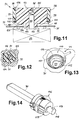
- FIG. 10 shows a slight modification in an oblique view a snap switch 64 acting as a device switch according to the invention.
- On the bent leg of an L-shaped Base plate 78 is a bimetallic strip similar to that in FIG. 9 66 attached by rivet heads 79.
- the Thermobimetal strip 66 is elongated and has at its free end an inwardly bent receiving section 80 on. This is attached with one in the middle Recording slot 81 provided that to the end of the strip 66 runs.
- an adjustment element Justierstatt 82 stored, which extends over the width of the Stripe 66 extends and in its central region flange-shaped diameter extension 83 carries.
- This diameter expansion is sometimes much more than that Strength of the strip 66 and forms one on its outer circumference Curve with preferably continuously increasing radius.
- the outer circumference of the diameter extension 83 is the adjusting pin 82 and thus the bimetallic strip 66 on the free End 70 of the snap spring 71.
- the distance due to the changing radius changeable between strip 66 and the snap spring end 70 is an advantageous embodiment of an adjustment device for the snap switch 64 according to one aspect of FIG present invention.
- the bimetallic strip 66 carries in Area of its attachment to the base plate 78 a heater 54 in the form of a metallic carrier velvet Thick film resistance heater 61 according to FIG. 8.
- a contact spring 84 lies on the tap contact field 59 and serves in addition to contacting the heating resistor 61 via the Connection contact field 58 and the carrier 55 to the base plate 78 as second contact.
- the advantage of this adjustment device is among others in that the direction of attack of the tool for adjustment of the adjusting pin 82 perpendicular to the direction of action of the Adjustment lies. This can lead to adulteration Adjustment due to the force of the tool on the Adjustment pin 82 can be avoided.
- the advantage of the illustrated Formation of the receiving section 80 with a Inward curvature lies in the fact that when heated of the bimetallic strip 66, the section is narrowed and thus the adjustment pin 82 is particularly firm and secure includes. To simplify the insertion of the pin 82 in the receiving portion 80 can the forked ends of the Strip as shown.
- An electrical switching device 89 is shown in section in FIG. 11 shown with a control axis 90, behind a front panel 91 of an electrical device, for example one Kitchen appliance is attached in a manner not shown.
- the control axis 90 extends through a through opening 92, whose diameter is, however, much larger.
- On the control axis 90 is a toggle inner part 93 of a shift knob 94.
- the receiving bore 95 corresponds to Cross-section of the control axis 90 formed with the special feature that the control axis 90 is axially movable therein.
- the inner part of the gag is supported by a spiral spring 96 in the area of the bottom of the mounting hole designed as a blind hole 95 against the control axis 90.
- Non-positive connection preferably also a positive connection, in the circumferential direction instead and the inner part can by means of the outer part be rotated.
- the through opening 92 is, as in FIG. 12, in the plan view becomes clear, essentially circular with a angular recess 104 formed. Is on the inner part 93 a projection 105 is formed, which protrudes into the opening 92.
- the Approach 105 corresponds to the opening 92 with a projection 106 corresponding to recess 104 is formed. In the normal state according to FIG. 11 there are protrusions 106 and Recess 104 substantially at one level so that the Approach 105 can not be rotated with the control axis 90, since the projection 106 abuts the recess 104.
- the control axis 90 To actuate the switching device 89 by turning the The control axis 90 must have the projection 106 out of the recess 104 to be brought. This is preferably done according to FIG. 11 axially sliding the inner part 93 onto the front oil end 91 to. However, the inner part 93 is pressed in via the Gag outer part 98 or its actuating surface 99. As a result the inner part of the gag is pushed towards the front panel 91 pressed until the limiting cams 107 abut the panel. Then the projection 106 no longer engages in the Recess 104 and is together with the inner part 93 opposite the front panel 91 rotatable.
- the spring constants of the spiral spring 96 and the are preferred Spring element 102 designed such that the coil spring 96 can be compressed much easier.
- This has the Advantage that by an axial pressing movement of the outer part 98 to the front panel 91 first the inner gag part 93 on the control axis 90 sliding against the screen , whereby the blocking device between approach 105 and Aperture is released. Only by further impressions with increased force, whereby the inner part with the limiting cams 107 supports against the bezel, gag outer and inner part engage and by a rotary movement of the outer part 98, the inner part 93 and thus the control axis 90 are rotated.
- This has the advantage that the Blocking device is released in an actuation stage, in which none of the outer gag part 98 on the inner part 93 Torques are transmitted and therefore no loads on the Blocking devices can occur.
- the outer gag part 98 relative to the inner part 93 and is therefore a position indicator of the inner part necessary. This can e.g. as a nose 108 be carried out, preferably in color from the toggle 94. As a further function it can be locked by Placing the outer gag part 98 on the inner part 93 den Secure the outer part against falling off by its front surface towering a bit.
- FIG. 12 shows a section within the front panel 91 an exemplary embodiment of the through opening 92 with an angular recess 104 which extends over an angular range extends from about 90 °.
- the approach 105 of the inner part of the gag 93 corresponds to the recess 104 with provided with a projection 106.
- In the approach 105 runs the on one side flattened control axis 90, wherein axially against each other without any significant friction are movable.
- a switchgear cover can be used instead of the front panel be trained accordingly and part of Form blocking device.
- FIG. 13 An alternative possibility of a blocking device shows Fig. 13.
- a possible embodiment of the receptacle is shown 44 in the base 31, which is used to hold the control axis 90 of the switching device 89 is used.
- the recording 44 exists essentially from a circular blind hole Recess 110 with a through hole 111. This has at a location similar to the through opening 92 in FIG. 12, a cutout 112 in the recess bottom 113.
- a flange-like one runs on the recess bottom 113 Projection 114, which is somewhat sharpened on its end face, at a certain distance from the walls of the recess 110.
- a control axis can be in the receptacle 44 according to FIG. 13 90 according to FIG. 14 are used.
- the maximum diameter the axis 90 is slightly below the diameter of the Projection 114.
- Cam rollers 116 attached.
- the inner recesses of the rollers 116 correspond to the cross section of the control axis 90 and point against this some play on, so the reels 116 are axially displaceable with respect to the axis.
- the projection 119 lies behind the recess bottom 113 and is no longer engaged with the cutout 112.
- the control axis 90 is then freely over a rotation angle of almost 360 °, and only in one single position, namely the starting position similar to FIG. 12, the blocking device snaps by the force of the spring again.
- a shift knob 94 can be fixed on the control axis 90 sit.
- the blocking device in the switchgear base 41 relocated, so the force to be applied from the base or the connection of the switching device 89 with a bracket or front panel 91 are adopted.
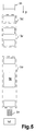
- a switch part 121 which is used for Slide switch is formed.
- a molded body 122 has a continuous thin switching arm 123 and a continuous thick switching arm 124, the central area is completely enclosed by the molded body.
- To the shift arms are based on the different material thickness 123 and 124 essentially the same as well as in the longitudinal direction of the Shaped body 122 or the sliding direction overlap arranged.
- embossing contact heads 125 In the area of the ends of the thin switching arm 123 are attached by embossing contact heads 125.
- dashed contact heads 126 made for switching higher electrical powers made of special contact material and by welding are attached.
- a triangular shaped rounded locking lug 128 formed at the front end of the molded body 122 at the front end of the molded body 122 .
- a cuboidal foam block 129 attached to the invention, for example by gluing. It serves as Compression spring for the elastic suspension of the switch part 121 against an attack.
- the advantages of such a voluminous Spring bodies made of plastic have an insulating effect. On the other hand, no elaborate leadership or the like. For the suspension needed, especially if the lateral extent is larger than that in the direction of loading.
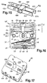
- FIG. 16 shows a plan view of a switchgear base 41 according to FIGS. 6 and 7.
- the Switch part 121 used in the longitudinal guide 42 is the Switch part 121 used.
- the foam block 129 is on the fastening tab 18 by bending an end portion the same attached.
- the advantage of additional gluing of the foam block 121 with the switch part 129 inter alia in that in this way the switch part is fixed on the foam block.
- a side Slipping can be done both by fastening of the foam block 129 as well as by a not shown, guide lug engaging in the longitudinal guide 42 be avoided.
- the locking lug 128 of the molded body 121 lies on a cam roller 116 on the control axis 90, in one Switching recess 130.
- the radial depth of the switching recess 130 corresponds to the distance shown between the contact heads 125 and 126 of the switch part 121 from the contact heads 14 of the Switchgear base 41 or slightly above.
- the switch recess 130 can a certain position of the control axis 90, for example the so-called zero position.
- the 16 is a built-in snap switch 64 9, but not at this point is discussed again.
- the grinder 72 lies on one Cam roller 116 omitted for clarity above that shown for the switch part 121.
- the Snap switch 64 can be by contact welding or riveting of the support plate 65 with the holding plate 48 on the switching device base be attached. After installing the snap switch the adjusting screw 60 is screwed into the receiving web 15.
- Fig. 17 shows an electrical switching device 89 according to the Invention with placed on the switchgear base 41 Housing cover 132. It is on by means of U-shaped tabs 133 the locking projections 52 of the base 41 without the aid of Tools attached by snapping on.
- the cover 132 has a central fastening strip 134, which is preferably made of thin metal or There is sheet metal. Symmetrical to the passage 135 for the Control axis 90, it has two prefabricated mounting holes 136 on, in the sheet metal screws or the like. can be screwed in. Alternatively, the holes 136 with prefabricated or pre-cut thread his.
- the distance between the inner pair of holes 136 can, for example, correspond to a US standard, the distance the outer pair of holes, for example an EC standard.
- the diameters of the bores 136 can be approximately 4 mm be. In the embodiment shown, the outer Bores 136 approximately over the screw receptacles 49 of the Switchgear socket 41 in Fig. 6. In this way, one Screwing not only the cover 132, but also of the base 41 carrying the actual switching devices with a holder, such as a front panel 91, possible.
- the adjusting screw 60 is visible, which also at attached cover 132 is accessible. This enables to adjust the switchgear when assembled, which is especially true for the temperature conditions inside important is.
- the separating webs 32 can also be seen.
Landscapes
- Manufacturing & Machinery (AREA)
- Engineering & Computer Science (AREA)
- Mechanical Engineering (AREA)
- Thermally Actuated Switches (AREA)
- Electrical Discharge Machining, Electrochemical Machining, And Combined Machining (AREA)
- Manufacture Of Switches (AREA)
- Switch Cases, Indication, And Locking (AREA)
- Electronic Switches (AREA)
- Relay Circuits (AREA)
- Control Of Resistance Heating (AREA)
- Control Of Electric Motors In General (AREA)
- Push-Button Switches (AREA)
- Oscillators With Electromechanical Resonators (AREA)
- Contacts (AREA)
- Cookers (AREA)
- Switches With Compound Operations (AREA)
- Manufacturing Of Electrical Connectors (AREA)
- Invalid Beds And Related Equipment (AREA)
- Accommodation For Nursing Or Treatment Tables (AREA)
- Control Of Motors That Do Not Use Commutators (AREA)
- Connections Arranged To Contact A Plurality Of Conductors (AREA)
- Apparatuses And Processes For Manufacturing Resistors (AREA)
Applications Claiming Priority (2)
| Application Number | Priority Date | Filing Date | Title |
|---|---|---|---|
| DE19833983A DE19833983A1 (de) | 1998-07-29 | 1998-07-29 | Verfahren zur Herstellung eines elektrischen Schaltgeräts und elektrisches Schaltgerät |
| DE19833983 | 1998-07-29 |
Publications (2)
| Publication Number | Publication Date |
|---|---|
| EP0977224A2 true EP0977224A2 (fr) | 2000-02-02 |
| EP0977224A3 EP0977224A3 (fr) | 2000-10-11 |
Family
ID=7875600
Family Applications (3)
| Application Number | Title | Priority Date | Filing Date |
|---|---|---|---|
| EP99114830A Withdrawn EP0977223A3 (fr) | 1998-07-29 | 1999-07-29 | Interrupteur electrique |
| EP99114837A Withdrawn EP0977224A3 (fr) | 1998-07-29 | 1999-07-29 | Procédé pour la fabrication d'un interupteur éléctrique |
| EP99114829A Expired - Lifetime EP0977231B1 (fr) | 1998-07-29 | 1999-07-29 | Interrupteur Electrique |
Family Applications Before (1)
| Application Number | Title | Priority Date | Filing Date |
|---|---|---|---|
| EP99114830A Withdrawn EP0977223A3 (fr) | 1998-07-29 | 1999-07-29 | Interrupteur electrique |
Family Applications After (1)
| Application Number | Title | Priority Date | Filing Date |
|---|---|---|---|
| EP99114829A Expired - Lifetime EP0977231B1 (fr) | 1998-07-29 | 1999-07-29 | Interrupteur Electrique |
Country Status (9)
| Country | Link |
|---|---|
| US (1) | US6211582B1 (fr) |
| EP (3) | EP0977223A3 (fr) |
| AT (1) | ATE256336T1 (fr) |
| AU (3) | AU757276B2 (fr) |
| DE (2) | DE19833983A1 (fr) |
| ES (1) | ES2212837T3 (fr) |
| NZ (2) | NZ336857A (fr) |
| TR (3) | TR199901812A2 (fr) |
| ZA (3) | ZA994839B (fr) |
Cited By (2)
| Publication number | Priority date | Publication date | Assignee | Title |
|---|---|---|---|---|
| EP1467445A2 (fr) * | 2003-04-11 | 2004-10-13 | E.G.O. ELEKTRO-GERÄTEBAU GmbH | Système d'appareil de commutation |
| EP4411774A1 (fr) | 2023-02-02 | 2024-08-07 | E.G.O. Elektro-Gerätebau GmbH | Dispositif de commutation et procédé de fonctionnement d'un dispositif de commutation |
Families Citing this family (24)
| Publication number | Priority date | Publication date | Assignee | Title |
|---|---|---|---|---|
| FR2785717B1 (fr) * | 1998-11-05 | 2000-12-08 | Schneider Electric Sa | Relais thermique dote d'un mecanisme a lame-ressort |
| DE10002625B4 (de) * | 2000-01-22 | 2010-03-11 | E.G.O. Elektro-Gerätebau GmbH | Verfahren zur Herstellung eines Schaltgerätesockels |
| JP3787482B2 (ja) * | 2000-04-17 | 2006-06-21 | ウチヤ・サーモスタット株式会社 | サーマルプロテクタ |
| DE20023912U1 (de) | 2000-06-24 | 2007-07-26 | Efen Gmbh | Stromverteiler |
| US20060256931A1 (en) * | 2002-03-11 | 2006-11-16 | Udo Bendig | Contact bank measurement arrangement including a contact bank telecommunications module provided with contact bank or a measurement arrangement and telecommunications assembly including plural modules |
| DE10317277A1 (de) * | 2003-04-11 | 2004-10-21 | E.G.O. Elektrogerätebau GmbH | Energiesteuergerät |
| JP2007006612A (ja) | 2005-06-23 | 2007-01-11 | Auto Network Gijutsu Kenkyusho:Kk | 電気接続箱 |
| DE102005058141A1 (de) * | 2005-12-06 | 2007-07-12 | Schaeffler Kg | Wälzlager mit Heizelement |
| AT503966B1 (de) * | 2006-07-06 | 2009-07-15 | Stanzbiegetechnik Gmbh | Verfahren zur herstellung von umspritzten formteilen |
| DE202006014058U1 (de) | 2006-09-06 | 2007-03-01 | E.G.O. Elektro-Gerätebau GmbH | Elektromechanisches Einstellgerät mit einer Drehachse |
| DE102007013154B4 (de) * | 2007-03-20 | 2009-04-02 | Mark Eidloth | Schaltgerät mit mindestens einem Kontaktpaar |
| DE102007044632B3 (de) * | 2007-09-19 | 2009-02-26 | Siemens Ag | Ansteuerbaugruppe eines Schaltgerätes sowie Schaltgerät |
| DE202008001002U1 (de) * | 2008-01-23 | 2008-05-21 | Schunk Bahn- Und Industrietechnik Gmbh | Verbindungsvorrichtung zur Bereitstellung elektrischer Anschlüsse |
| DE102008014805A1 (de) | 2008-03-10 | 2009-03-05 | E.G.O. Elektro-Gerätebau GmbH | Leistungssteuergerät für ein Elektro-Haushaltsgerät und Verfahren zum Betrieb eines Leistungssteuergeräts |
| DE102009060125A1 (de) | 2009-12-17 | 2011-06-22 | E.G.O. Elektro-Gerätebau GmbH, 75038 | Elektronische Steuerung für ein Kochgerät und Steuerverfahren |
| US8884195B2 (en) | 2011-12-09 | 2014-11-11 | E.G.O. Elektro-Gerätebau GmbH | Heating device, method of producing a heating device and method for operating a heating device |
| US8933377B2 (en) | 2011-12-09 | 2015-01-13 | E.G.O. Elektro-Gerätebau GmbH | Control device for an electrical heating device for a cooking field, cooking field and method for operating such an electrical heating device |
| DE102012218500A1 (de) * | 2012-10-11 | 2014-04-17 | Continental Automotive Gmbh | Vorrichtung zum Verbinden von elektrischen Energiespeichern zu einer Batterie und Herstellungsverfahren für eine solche Vorrichtung |
| WO2016063583A1 (fr) * | 2014-10-20 | 2016-04-28 | ウチヤ・サーモスタット株式会社 | Interrupteur de température |
| DE102016224069A1 (de) | 2016-12-02 | 2018-06-07 | E.G.O. Elektro-Gerätebau GmbH | Kochgerät mit einer Kochplatte und einer Heizeinrichtung darunter |
| CN106783304B (zh) * | 2017-01-13 | 2018-08-14 | 尹志强 | 放置薄膜开关弹片的连续旋转机构 |
| US10186387B1 (en) | 2017-09-21 | 2019-01-22 | E.G.O. Elektro-Geraetebau Gmbh | Electrical control device |
| DE102019216020A1 (de) | 2019-10-17 | 2021-04-22 | E.G.O. Elektro-Gerätebau GmbH | Verfahren zum Betrieb einer Strahlungsheizeinrichtung und Kombination einer Strahlungsheizeinrichtung mit einer Drehschalteinrichtung |
| DE102021202314A1 (de) | 2021-03-10 | 2022-09-15 | E.G.O. Elektro-Gerätebau GmbH | Leistungssteuergerät und Anordnung eines solchen Leistungssteuergeräts mit einer elektrischen Heizeinrichtung |
Citations (5)
| Publication number | Priority date | Publication date | Assignee | Title |
|---|---|---|---|---|
| DE2625716A1 (de) * | 1976-06-09 | 1977-12-15 | Ego Elektro Blanc & Fischer | Leistungssteuergeraet |
| US4656733A (en) * | 1985-09-03 | 1987-04-14 | Omron Tateisi Electronics Co. | Method of manufacture of base assembly for an electromagnetic relay |
| DE19511877A1 (de) * | 1995-03-31 | 1996-10-02 | Eaton Controls Gmbh | Kontakteinheit, insbesondere für elektrische Schalter |
| EP0780862A2 (fr) * | 1995-12-22 | 1997-06-25 | ITW Fastex Italia S.p.A. | Procédé de fabrication d'un commutateur d'alimentation particulièrement pour appareils électroménagers ou similaires et commutateur ainsi produit |
| US5770825A (en) * | 1995-07-27 | 1998-06-23 | Omron Corporation | Switch device |
Family Cites Families (16)
| Publication number | Priority date | Publication date | Assignee | Title |
|---|---|---|---|---|
| US3202166A (en) | 1959-05-29 | 1965-08-24 | Parker Hannifin Corp | Shut-off valve assembly having a removable plug |
| US3203166A (en) * | 1961-09-08 | 1965-08-31 | Texas Instruments Inc | Thermostatic elements |
| FR1332034A (fr) * | 1961-12-21 | 1963-12-16 | ||
| US4206344A (en) | 1976-06-09 | 1980-06-03 | E.G.O. Regeltechnik Gmbh | Electric power controllers |
| US4471338A (en) * | 1982-06-02 | 1984-09-11 | White Consolidated Industries, Inc. | Thermal cycling switch |
| DE3508248A1 (de) * | 1985-03-08 | 1986-09-11 | E.G.O. Elektro-Geräte Blanc u. Fischer, 7519 Oberderdingen | Elektrische beheizung fuer ein bimetall, insbesondere fuer ein elektrisches leistungssteuergeraet |
| IT206626Z2 (it) * | 1985-07-30 | 1987-09-08 | Vebe Elettromecc | Termostato dotato di morsetti d'uscita allineati. |
| JPH0677425B2 (ja) * | 1985-10-14 | 1994-09-28 | 生方 眞哉 | 熱応動スナツプスイツチ |
| DE3710387A1 (de) | 1987-04-01 | 1988-10-13 | Thermostat & Schaltgeraetebau | Leistungssteuergeraet |
| DE4003745A1 (de) * | 1990-02-08 | 1991-08-14 | Ego Elektro Blanc & Fischer | Schaltgeraet |
| DE4206157A1 (de) * | 1992-02-28 | 1993-09-16 | Hofsass P | Thermoschalter |
| DE9305073U1 (de) * | 1993-04-02 | 1993-06-09 | Schaltbau AG, 81677 München | Mikroschalter |
| US5311165A (en) * | 1993-04-21 | 1994-05-10 | Harper-Wyman Company | Modular electric/gas oven thermostat and assembly method |
| EP0678882B1 (fr) * | 1994-04-19 | 2000-06-28 | Marquardt GmbH | Interrupteur électrique et son procédé de fabrication |
| US6034598A (en) * | 1996-07-19 | 2000-03-07 | Delta Schoeller, Ltd. | Hazard warning switch for motor vehicles |
| DE29710464U1 (de) * | 1997-06-16 | 1997-08-14 | E.G.O. Elektro-Gerätebau Gmbh, 75038 Oberderdingen | Wandungselement |
-
1998
- 1998-07-29 DE DE19833983A patent/DE19833983A1/de not_active Withdrawn
-
1999
- 1999-07-21 NZ NZ336857A patent/NZ336857A/xx not_active IP Right Cessation
- 1999-07-28 AU AU41161/99A patent/AU757276B2/en not_active Ceased
- 1999-07-28 NZ NZ336957A patent/NZ336957A/xx unknown
- 1999-07-28 AU AU41163/99A patent/AU759332B2/en not_active Ceased
- 1999-07-28 AU AU41162/99A patent/AU4116299A/en not_active Abandoned
- 1999-07-28 ZA ZA9904839A patent/ZA994839B/xx unknown
- 1999-07-29 TR TR1999/01812A patent/TR199901812A2/xx unknown
- 1999-07-29 TR TR1999/01814A patent/TR199901814A3/tr unknown
- 1999-07-29 EP EP99114830A patent/EP0977223A3/fr not_active Withdrawn
- 1999-07-29 DE DE59907994T patent/DE59907994D1/de not_active Expired - Fee Related
- 1999-07-29 US US09/364,229 patent/US6211582B1/en not_active Expired - Fee Related
- 1999-07-29 ZA ZA9904878A patent/ZA994878B/xx unknown
- 1999-07-29 AT AT99114829T patent/ATE256336T1/de not_active IP Right Cessation
- 1999-07-29 EP EP99114837A patent/EP0977224A3/fr not_active Withdrawn
- 1999-07-29 TR TR1999/01813A patent/TR199901813A2/xx unknown
- 1999-07-29 EP EP99114829A patent/EP0977231B1/fr not_active Expired - Lifetime
- 1999-07-29 ZA ZA9904877A patent/ZA994877B/xx unknown
- 1999-07-29 ES ES99114829T patent/ES2212837T3/es not_active Expired - Lifetime
Patent Citations (5)
| Publication number | Priority date | Publication date | Assignee | Title |
|---|---|---|---|---|
| DE2625716A1 (de) * | 1976-06-09 | 1977-12-15 | Ego Elektro Blanc & Fischer | Leistungssteuergeraet |
| US4656733A (en) * | 1985-09-03 | 1987-04-14 | Omron Tateisi Electronics Co. | Method of manufacture of base assembly for an electromagnetic relay |
| DE19511877A1 (de) * | 1995-03-31 | 1996-10-02 | Eaton Controls Gmbh | Kontakteinheit, insbesondere für elektrische Schalter |
| US5770825A (en) * | 1995-07-27 | 1998-06-23 | Omron Corporation | Switch device |
| EP0780862A2 (fr) * | 1995-12-22 | 1997-06-25 | ITW Fastex Italia S.p.A. | Procédé de fabrication d'un commutateur d'alimentation particulièrement pour appareils électroménagers ou similaires et commutateur ainsi produit |
Cited By (4)
| Publication number | Priority date | Publication date | Assignee | Title |
|---|---|---|---|---|
| EP1467445A2 (fr) * | 2003-04-11 | 2004-10-13 | E.G.O. ELEKTRO-GERÄTEBAU GmbH | Système d'appareil de commutation |
| EP1467445A3 (fr) * | 2003-04-11 | 2006-05-17 | E.G.O. ELEKTRO-GERÄTEBAU GmbH | Système d'appareil de commutation |
| EP4411774A1 (fr) | 2023-02-02 | 2024-08-07 | E.G.O. Elektro-Gerätebau GmbH | Dispositif de commutation et procédé de fonctionnement d'un dispositif de commutation |
| DE102023200840A1 (de) | 2023-02-02 | 2024-08-08 | E.G.O. Elektro-Gerätebau GmbH | Schaltvorrichtung und Verfahren zum Betrieb einer Schaltvorrichtung |
Also Published As
| Publication number | Publication date |
|---|---|
| AU4116299A (en) | 2000-02-24 |
| DE59907994D1 (de) | 2004-01-22 |
| TR199901814A2 (xx) | 2000-02-21 |
| AU759332B2 (en) | 2003-04-10 |
| TR199901813A3 (tr) | 2000-02-21 |
| EP0977231B1 (fr) | 2003-12-10 |
| ZA994877B (en) | 2000-02-04 |
| ZA994878B (en) | 2000-02-15 |
| NZ336957A (en) | 2000-03-27 |
| EP0977223A3 (fr) | 2000-10-11 |
| ATE256336T1 (de) | 2003-12-15 |
| NZ336857A (en) | 2000-07-28 |
| AU757276B2 (en) | 2003-02-13 |
| ZA994839B (en) | 2000-02-15 |
| TR199901813A2 (xx) | 2000-02-21 |
| EP0977231A2 (fr) | 2000-02-02 |
| ES2212837T3 (es) | 2004-08-01 |
| AU4116399A (en) | 2000-02-24 |
| TR199901814A3 (tr) | 2000-02-21 |
| EP0977223A2 (fr) | 2000-02-02 |
| TR199901812A2 (xx) | 2000-02-21 |
| US6211582B1 (en) | 2001-04-03 |
| DE19833983A1 (de) | 2000-02-03 |
| AU4116199A (en) | 2000-02-24 |
| EP0977224A3 (fr) | 2000-10-11 |
| EP0977231A3 (fr) | 2000-10-11 |
Similar Documents
| Publication | Publication Date | Title |
|---|---|---|
| EP0977224A2 (fr) | Procédé pour la fabrication d'un interupteur éléctrique | |
| EP0887826B1 (fr) | Interrupteur à commande thermique avec pont de contact | |
| EP0863527B1 (fr) | Interrupteur à commande thermique avec pont de contact | |
| EP0268098B1 (fr) | Appareil de commutation électrique, en particulier pour commande de puissance | |
| DE3104827C2 (fr) | ||
| EP1764813A1 (fr) | Interrupteur électrique | |
| DE3233909A1 (de) | Schnappvorrichtung, insbesondere elektrischer schnappschalter | |
| EP0860846B1 (fr) | Régulateur électrique de puissance, en particulier pour appareil à chauffage électrique | |
| DE202016104274U1 (de) | Thermische Schalteinrichtung | |
| DE2502579C2 (de) | Druckknopfbetaetigter ueberstromschalter mit thermischer ausloesung | |
| EP2650897B1 (fr) | Commutateur électrique sensible à la température et son procédé de fabrication | |
| DE2724527A1 (de) | Temperaturregler | |
| DE19704575C1 (de) | Schaltgerät | |
| DE19507488C2 (de) | Halter für ein Bimetall-Schaltwerk sowie Temperaturwächter mit einem Bimetall-Schaltwerk | |
| DE102012106978B4 (de) | Temperaturschalter sowie Verfahren zur Justierung eines Temperaturschalters | |
| DE202005019880U1 (de) | Temperaturregler und Kombination von Temperaturregler und Temperatursicherung | |
| DE1055649B (de) | Temperaturabhaengiger elektrischer Schalter mit Rueckstelleinrichtung | |
| DE19537253C2 (de) | Kippschalter | |
| EP0865058B1 (fr) | Régulateur électrique de puissance, en particulier pour appareils de chauffage électrique | |
| DE19706249B4 (de) | Elektrisches Steuergerät, insbesondere für Elektrowärmegeräte und Verfahren zu seiner Herstellung | |
| DE69816419T2 (de) | Anschlusskontaktanordnung für integrierte schalteinheit | |
| DE19706250A1 (de) | Elektrisches Steuergerät, insbesondere für Elektrowärmegeräte | |
| DE2747974C3 (de) | Schutzrohrankerkontaktrelais | |
| EP1139369A2 (fr) | Dispositif interrupteur commandé thermiquement | |
| AT512726B1 (de) | Temperaturempfindlicher elektrischer Schalter und Verfahren zu dessen Herstellung |
Legal Events
| Date | Code | Title | Description |
|---|---|---|---|
| PUAI | Public reference made under article 153(3) epc to a published international application that has entered the european phase |
Free format text: ORIGINAL CODE: 0009012 |
|
| AK | Designated contracting states |
Kind code of ref document: A2 Designated state(s): AT BE CH CY DE DK ES FI FR GB GR IE IT LI LU MC NL PT SE |
|
| AX | Request for extension of the european patent |
Free format text: AL;LT;LV;MK;RO;SI |
|
| PUAL | Search report despatched |
Free format text: ORIGINAL CODE: 0009013 |
|
| AK | Designated contracting states |
Kind code of ref document: A3 Designated state(s): AT BE CH CY DE DK ES FI FR GB GR IE IT LI LU MC NL PT SE |
|
| AX | Request for extension of the european patent |
Free format text: AL;LT;LV;MK;RO;SI |
|
| 17P | Request for examination filed |
Effective date: 20010317 |
|
| AKX | Designation fees paid |
Free format text: AT BE CH CY DE DK ES FI FR GB GR IE IT LI LU MC NL PT SE |
|
| AXX | Extension fees paid |
Free format text: SI PAYMENT 20010317 |
|
| 17Q | First examination report despatched |
Effective date: 20021122 |
|
| STAA | Information on the status of an ep patent application or granted ep patent |
Free format text: STATUS: THE APPLICATION IS DEEMED TO BE WITHDRAWN |
|
| 18D | Application deemed to be withdrawn |
Effective date: 20030603 |