EP0977074A2 - Integrierter optischer Chip mit Verringerung des durch pyroelektrischen Effekt induzierten thermischen Fehlers - Google Patents
Integrierter optischer Chip mit Verringerung des durch pyroelektrischen Effekt induzierten thermischen Fehlers Download PDFInfo
- Publication number
- EP0977074A2 EP0977074A2 EP99114791A EP99114791A EP0977074A2 EP 0977074 A2 EP0977074 A2 EP 0977074A2 EP 99114791 A EP99114791 A EP 99114791A EP 99114791 A EP99114791 A EP 99114791A EP 0977074 A2 EP0977074 A2 EP 0977074A2
- Authority
- EP
- European Patent Office
- Prior art keywords
- face
- foot
- chip
- conductive
- optics chip
- Prior art date
- Legal status (The legal status is an assumption and is not a legal conclusion. Google has not performed a legal analysis and makes no representation as to the accuracy of the status listed.)
- Granted
Links
Images

Classifications
-
- G—PHYSICS
- G02—OPTICS
- G02F—OPTICAL DEVICES OR ARRANGEMENTS FOR THE CONTROL OF LIGHT BY MODIFICATION OF THE OPTICAL PROPERTIES OF THE MEDIA OF THE ELEMENTS INVOLVED THEREIN; NON-LINEAR OPTICS; FREQUENCY-CHANGING OF LIGHT; OPTICAL LOGIC ELEMENTS; OPTICAL ANALOGUE/DIGITAL CONVERTERS
- G02F1/00—Devices or arrangements for the control of the intensity, colour, phase, polarisation or direction of light arriving from an independent light source, e.g. switching, gating or modulating; Non-linear optics
- G02F1/01—Devices or arrangements for the control of the intensity, colour, phase, polarisation or direction of light arriving from an independent light source, e.g. switching, gating or modulating; Non-linear optics for the control of the intensity, phase, polarisation or colour
- G02F1/03—Devices or arrangements for the control of the intensity, colour, phase, polarisation or direction of light arriving from an independent light source, e.g. switching, gating or modulating; Non-linear optics for the control of the intensity, phase, polarisation or colour based on ceramics or electro-optical crystals, e.g. exhibiting Pockels effect or Kerr effect
- G02F1/035—Devices or arrangements for the control of the intensity, colour, phase, polarisation or direction of light arriving from an independent light source, e.g. switching, gating or modulating; Non-linear optics for the control of the intensity, phase, polarisation or colour based on ceramics or electro-optical crystals, e.g. exhibiting Pockels effect or Kerr effect in an optical waveguide structure
-
- G—PHYSICS
- G02—OPTICS
- G02F—OPTICAL DEVICES OR ARRANGEMENTS FOR THE CONTROL OF LIGHT BY MODIFICATION OF THE OPTICAL PROPERTIES OF THE MEDIA OF THE ELEMENTS INVOLVED THEREIN; NON-LINEAR OPTICS; FREQUENCY-CHANGING OF LIGHT; OPTICAL LOGIC ELEMENTS; OPTICAL ANALOGUE/DIGITAL CONVERTERS
- G02F2203/00—Function characteristic
- G02F2203/21—Thermal instability, i.e. DC drift, of an optical modulator; Arrangements or methods for the reduction thereof
Definitions
- the invention relates to the field of integrated optics chips or devices and more particularly to the field of multifunction integrated optics chips such as those having integrated optic circuits formed on Lithium Niobate (LiNbO 3 ) substrates.
- Integrated optics chips are designed to include waveguides and to perform functions such as "Y”, “Y-Y”, or Star spliters or couplers, WDM (Wavelength Dependent Couplers) and modulators. Multiple functions are incorporated on a single device eliminating losses and errors associated with individual interface optical coupling.
- the devices are usually fabricated in large numbers on three to four inch wafers of Lithium Niobate (LiNbO 3 ) using conventional photomasks, vacuum deposition, chemical baths and etching techniques to form large numbers of identical components at low cost and with high reliability.
- MIOC's Multifunction Integrated Optical Chips or Components
- circuits capable of performing many of the aforementioned functions are necessary for the fabrication of middle and high accuracy fiber optic gyros (FOGS) or rotation sensors that rely on the principle of Sagnac interferometers and possibly other interferometric fiber optic sensors such as hydrophones that rely on the principles of the Mach-Zehnder or Michaelson Interferometers requiring high stability.
- FOGS middle and high accuracy fiber optic gyros
- rotation sensors that rely on the principle of Sagnac interferometers and possibly other interferometric fiber optic sensors such as hydrophones that rely on the principles of the Mach-Zehnder or Michaelson Interferometers requiring high stability.
- the test MIOC chip was made of Lithium Niobate (LiNbO 3 ) and was similar in size to the related art device shown in Figure 1.
- the inventors related the discharge to a pyroelectric effect and calculated that a device of that width would generate voltages across the 2 mm width of the chip of above 100 volts per degree centigrade.
- the pyroelectric effect observed might also be related to a FOG power hysteresis problem also under investigation in which a charge differential developed across the face of a MIOC chip due to temperature change.
- the hysteresis problem exhibits itself as a slight change in the transmitted power of a FOG instrument as the instrument is first taken through a positive or negative temperature change followed by a negative or positive temperature change.
- the charge differential that develops across the face of the chip results in a charge leakage across the face of the chip.
- the time and temperature dependent effects combine to contribute to a slight hysteresis in the transmitted power of the instrument and to the efficiency of the waveguides in the MIOC to propagate light.
- Integrated optics chips such as those characterized in this application are formed using processes and steps similar to some of those found in related U.S. Patents such as U.S. Pat. No. 5,193,136 filed 11/26/91 for a "PROCESS FOR MAKING MULTIFUNCTION INTEGRATED OPTICS CHIPS HAVING HIGH ELECTRO-OPTIC COEFFICIENTS" which issued to Dr. Chin L. Chang et al on Mar. 9, 1993; U.S. Pat. No. 5,046,808 filed 12/18/89 for an "INTEGRATED OPTICS CHIP AND METHOD OF CONNECTING OPTICAL FIBER THERETO" which issued to Dr. Chin L. Chang On Sept. 10, 1991; U.S.
- This application is particularly directed to methods and apparatus for the reduction of errors produced in an integrated optics chip, formed to function as an optical modulator, as a result of temperature changes which result in voltage differences across the surface of chip due to the Pyroelectric Effect.
- the field that produces the voltage differences across the surface of the chip is caused by any change in the bulk temperature of the chip.
- a temperature gradient across the chip is not required to produce a voltage difference due to the pyroelectric effect.
- the effect is produced when ever the temperature of the chip is changed from one value to another such as from room temperature to 100 degrees fahrenheit.
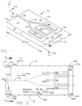
- Figure 1 provides a schematic perspective view representation of an optics chip 10 formed on a substrate 11 of Lithium Niobate as shown in U.S. 5,442,719 having a top surface 12, orthogonal to a +Z face 14, a -Z face 16 on the opposing side. As shown in the sectional view of Figure 4, a portion of the +Z and -Z faces 14, 16 are coated at least partially with a conductive coating 15, 17 such as conductive epoxy or metal.
- a conductive coating 15, 17 such as conductive epoxy or metal.
- the chip 10 is formed from a crystal having a high electro-optic coefficient, such as Lithium Niobate (LiNbO 3 ).
- the crystal axes are illustrated showing the +Z crystal axis extending outward from the +Z face, the +X axis extending upward from the top surface 12 and the +Y axis extending to the right along the longitudinal axis.
- the Z axis is the axis across which a pyroelectric effect is exhibited.
- a dimension of 20 mm along the Y axis, a width of 2 mm along the Z axis, and a thickness of 1 mm along the X axis are illustrative and are only provided to show what the size might be of a typical optical chip 10.
- the optical chip 10 of Figure 1 combines the functions of a polarizer, a single "Y” spliter and a modulator to form a MIOC (multifunction integrated optic chip) 10 as might be used in a conventional fiber optic gyro.
- the input waveguide 18 receives light from input port 20 on input face 22.
- the input waveguide branches at the "Y" junction 24 to a first output waveguide 26 coupled to a first output port 28 on output face 30, and a second output waveguide 32 coupled to a second output port 34 also on the output face 30.
- the input and output waveguides connect to or comprise a waveguide network which in the present case comprises a "Y " splitter in combination with a phase modulator having modulator plates 38a, 38b and 38c.
- Figure 2 is a schematic top view of the optical chip of Figure 1.
- Figure 2 shows conductive paths 40a and 40b coupling, via conductive security dabs 52a - 52d and 50a - 50d, the +Z face 14 and -Z face 16 to prevent a charge differential from developing between the +Z and -Z faces.
- the conductive security dabs 52a - 52d and 50a - 50d are used to increase reliability of the conductive paths 40a, 40b which might be degraded by temperature cycling or variations in the quality of metalization applied to the respective feet.
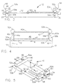
- Figure 3 is a side elevation of Figure 2 showing a first foot 46 on the top surface 12 of the optical chip 10.
- Conductive security dab 50b bridges the gap 53b between the side surface 44b of the first foot 46 and the conductive coating 17 on the -Z face 16.
- Conductive security dab 50d bridges the gap between the conductive coating on the -Z face of the second foot 54 and the conductive surface 17 on the -Z face.
- Figure 4 is a sectional of Figure 3 taken on section line 4 - 4 of Figure 2.
- the conductive paths 40a is formed on the top surface 42 of the first foot 46.
- the conductive path 40a is shown covering the side surfaces 44a, 44b of a first foot 46.
- the base face 47 of the first foot 46 is parallel to and under the top surface 42.
- the base face 47 is bonded to top surface 12 of the optics chip 10.
- FIG. 4 shows conducting security dabs 50a provides a conductive path from the conductive coating 40a on the left edge of foot 46 to the conductive coating 15 on the +Z face 14.
- Conductive dab 50b provides a conductive path from the conductive coating 40a on the right side of foot 46 to the conductive coating 17 on the -Z face 16 of the optics chip and bridges the gap 53b between the side surface 44b of the first foot 46 and the conductive coating 17 on the -Z face 16.
- first foot 46 has butt face 49 aligned to be co-planar with the input face 22 of the optic chip 10.
- Second foot 54 has butt face 56 aligned to be co-planar with the output face 30 of the optic chip 10.
- Figure 5 shows the combination of a first foot 46 having its butt face 49 aligned to be co-planar with input face 22 and the corresponding input port 20 (not shown) and second foot 54 with its butt face 56 aligned to be co-planar with the output face 30 and the corresponding waveguide first and second output ports 28, 34.
- aligning the first foot butt face 49 or the second foot butt face 56 with a corresponding end of the optic chip 10 provides an extended or expanded surface with the respective input or output face 22, 30 for bonding a fiber optic pigtail such as pigtails 58, 60, 62 to the respective input or output port such as described in U.S. Patent 4,975,506 to Pavlath reference supra.
- the conductive coating 40a, 40b on each respective foot and on the +Z face and on the -Z face of the optics chip is preferably metal deposited thereon by vacuum deposition or sputtering.
- the feet are preferably formed by slicing a wafer of lithium niobate crystal.
- each foot is positioned on the optics chip with its respective +Z axis aligned to be opposite in direction to the +Z axis of the optics chip.
- Figure 6 is a top view of a packaged device, typically a hermetically sealed can 66, optical pigtails 58, 60, 62 extending therefrom and electrical contacts extending from the sides for driving internal circuitry (not shown) such as the phase modulator 36 electrodes 38a, 38b and 38c (not shown).
- internal circuitry such as the phase modulator 36 electrodes 38a, 38b and 38c (not shown).
- Figure 7 is a side sectional view of Figure 6 taken on line 7 - 7 to show the optical chip 10 mounted in sealed can 66.
- the +Z and -Z faces of the optic chip are coated with a conductive coating such as metal.
- the base face of the optic chip is bonded by a conductive adhesive 72 to a mounting surface in the protective package 66.
- the adhesive 72 may form a direct contact with the metalization on the +Z face 14 and the -Z face 16 along a respective lower edge of the optic chip 10.
- the adhesive is blended to be sufficiently conductive to bleed off a charge between the +Z and -Z faces.
- metalized feet, conductive dabs and conductive adhesive 72 or conductive epoxy has been proposed as means for conductively connecting the conductive coating on the +Z face to the conductive coating on the -Z face.
- An electrical lead or a gold flying lead connecting the two faces to each other or to a common terminal is expected to also provide a means for conductively connecting the conductive coating on the +Z face to the conductive coating on the -Z face.
- Figures 2, 3, 4 and 5 show bonding pad 76 in combination with conductive security dab 50c as an example of a contact pad to which a flying lead can be bonded.
- a circuit trace 78 is shown in Figure 2 leading to a modulator plate 38a.
- Contact pads 82a, 82b, 82c are connected to modulator drive circuitry. Connecting the conductive coatings 15 of the +Z face to the conductive coating 17 on the -Z face and to the modulator circuitry via dab 50c, pad 76 and trace 78 to modulator pad 82a as shown in Figure 2 prevents the conductive coating from floating and collecting a static charge.
- modulator pads 82a and 82c are connected together and exit the optic chip at a first bonding pad to be driven from a first signal source.
- a second signal source out of phase with the first, drives the pad 82b.
- a second pad is connected to pad 82b. Tests have shown that this acceptable for to grounding the conductive coating and eliminating the saturation problem.
- the process or method for producing an optics chip having a top surface, a +Z face, a -Z face, the optic chip being formed from a crystal having a high electro-optic coefficient and having at least one input face having at least one waveguide input port comprises the steps of:
- the method is further characterized by coating at least a portion of the +Z and -Z faces with a conductive coating and more particularly by the step of metalizing the +Z face and -Z face using vacuum deposition.
- the method or process is also enhanced by forming at least one foot of lithium niobate to have a base surface, a first and second side surface and a top surface, and then metalizing the first and second side surface and a top surface of the foot using vacuum deposition.
- the feet are then positioned and the base surface of the foot is bonded onto the top surface of the optic chip.
- the surfaces of the foot are metalized forming a conductive bridge from the metalization on the +Z face to the metalization on the -Z face.
- Conductive security dabs of conducting adhesive are positioned to conductively couple the metalization on the surfaces of the foot to the metalization on the +Z face and to the metalization on the -Z face. These conductive security dabs are to insure that the continuity will be maintained, even if the metal breaks at the bond line between foot and chip and at the sharp corners of the chip where there may be high stress.
- Figure 8a shows a large number of optical chips on a wafer before the wafer is diced. Foot strips of Lithium Niobate (LiNbO 3 ) 74a, 74b, 74c, 74d are first bonded across the wafer in an array of rows taking care to orientate the +Z axis of each Lithium Niobate (LiNbO 3 ) strip to have the required orientation based on the orientation of the +Z axis of the wafer and the optic chips thereon.
- LiNbO 3 Lithium Niobate
- the wafer would then be sliced along paths such as 78a, 78b to separate the wafer into columns of optical chips each having two feet attached to its surface.
- the optical chips are then masked as strips or after being sliced into individual optical chips to permit the vacuum deposition of metal from a position above the top surface of the optical chip through the mask.
- the metal is deposited to cover the top surface of each foot, the sides of the optical chip and feet and to fill in the gap between the side of the foot and the metalized surface of the side of the optical chip.
- the preferred conducting layer is vacuum evaporated or sputtered metal of the same type used for the modulator electrodes 38a - 38c and pads 76, 82a - 82c.
- a composite layer of first titanium and then gold is sometimes used.
- the conducting path 40a or strap across the top of the foot could be put on at the wafer level before the wafer is diced into feet as characterized in the following process or method.
- a top view of a wafer two rows of optics chips having a top surface, a +Z face, a -Z face, are formed on the crystal wafer, the crystal material having a high electro-optic coefficient.
- Each optic chip has at least one input face, and at least one waveguide input port. The method comprises the steps of:
- Figure 8b shows a slice of the wafer. Slicing the wafer after the foot strips 74a - 74d are bonded is a process step that eliminates the step between the side of the foot and the surface of the optical chip shown in Figure 4.
- each foot (approximately 2 mm) is typically sightly less than the width of the optical chip.
- the slight difference in width between the foot and the width of the optical chip causes a the step that is shown in an exaggerated manner in Figure 4.
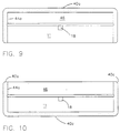
- Figure 9 characterizes a sectional view taken along a section line such as 9 - 9 of Figure 8b to illustrate how the metalized coating would cover the foot, the sides of the optical chip and bridge the gap between the top of the foot and the sides of the optical chip. If the metalization of the foot and sides of the optical chip is developed to be sufficiently uniform and reliable, use of the conductive security dabs may be eliminated.
- Figure 10 depicts an alternative arrangement in which the conductive path 40a across the top of the foot is omitted and a conductive path 40c is placed across the bottom of the substrate 11.
- the +Z and -Z faces are shorted together by the metalization on the base of substrate 11 even without the use of feet.
- Each foot is bonded to the top surface of the optical chip using an adhesive such as Norland 83H.
- the layer of adhesive can be as much as a couple of microns thick. The layer of adhesive may not reach the side of the foot in some instances leaving a slight gap 53a, 53b under the foot. Gaps 53a, 53b are depicted under the left and right edges of the foot in Figure 4. Putting the foot strips 74a - 74d on the wafer before slicing and dicing will produce a more uniform bond line under each individual foot. Aligning the feet to have the proper polarity and bonding the feet on an optic chip will be more economically controlled by bonding the foot strips to the wafer and then by slicing and dicing the wafer.
- the present first choice for the conducting layer is deposited metal by either thermal evaporation or sputtering; however, other coatings can be used such as a high resistivity sputtered palladium-gold and graphite paint.
- the invention relates to an Integrated Optics Chip comprising:
Landscapes
- Physics & Mathematics (AREA)
- Nonlinear Science (AREA)
- Chemical & Material Sciences (AREA)
- Engineering & Computer Science (AREA)
- Ceramic Engineering (AREA)
- Crystallography & Structural Chemistry (AREA)
- General Physics & Mathematics (AREA)
- Optics & Photonics (AREA)
- Optical Integrated Circuits (AREA)
- Optical Modulation, Optical Deflection, Nonlinear Optics, Optical Demodulation, Optical Logic Elements (AREA)
- Optical Couplings Of Light Guides (AREA)
Applications Claiming Priority (2)
| Application Number | Priority Date | Filing Date | Title |
|---|---|---|---|
| US09/123,955 US6044184A (en) | 1998-03-31 | 1998-07-28 | Integrated optics chip with reduced thermal errors due to pyroelectric effects |
| US123955 | 1998-07-28 |
Publications (3)
| Publication Number | Publication Date |
|---|---|
| EP0977074A2 true EP0977074A2 (de) | 2000-02-02 |
| EP0977074A3 EP0977074A3 (de) | 2000-07-12 |
| EP0977074B1 EP0977074B1 (de) | 2008-09-03 |
Family
ID=22411904
Family Applications (1)
| Application Number | Title | Priority Date | Filing Date |
|---|---|---|---|
| EP99114791A Expired - Lifetime EP0977074B1 (de) | 1998-07-28 | 1999-07-28 | Integrierter optischer Chip mit Verringerung des durch pyroelektrischen Effekt induzierten thermischen Fehlers |
Country Status (6)
| Country | Link |
|---|---|
| US (1) | US6044184A (de) |
| EP (1) | EP0977074B1 (de) |
| JP (2) | JP4388169B2 (de) |
| CA (1) | CA2279066C (de) |
| DE (1) | DE69939444D1 (de) |
| IL (1) | IL131058A (de) |
Cited By (2)
| Publication number | Priority date | Publication date | Assignee | Title |
|---|---|---|---|---|
| EP1500965A1 (de) * | 2003-07-22 | 2005-01-26 | Fujitsu Limited | Optische Wellenleitervorrichtung mit optischem Modulator und Verfahren zu deren Herstellung |
| EP1939669A4 (de) * | 2005-09-30 | 2009-11-25 | Sumitomo Osaka Cement Co Ltd | Lichtmodulator und verfahren zu seiner herstellung |
Families Citing this family (11)
| Publication number | Priority date | Publication date | Assignee | Title |
|---|---|---|---|---|
| KR100357629B1 (ko) * | 2000-05-03 | 2002-10-25 | 삼성전자 주식회사 | 다분기 열광학 스위치 |
| US6445455B1 (en) | 2000-05-23 | 2002-09-03 | Northrop Grumman Corporation | Phase and intensity modulated IFOG |
| EP1400820A1 (de) * | 2002-09-20 | 2004-03-24 | Corning O.T.I. SRL | Integriert-optischer Chip |
| WO2004092792A1 (ja) * | 2003-04-16 | 2004-10-28 | Fujitsu Limited | 光導波路デバイス |
| JP2013186200A (ja) * | 2012-03-06 | 2013-09-19 | Japan Oclaro Inc | 光モジュール、及び光送信器 |
| JP2016142755A (ja) * | 2015-01-29 | 2016-08-08 | 富士通オプティカルコンポーネンツ株式会社 | 光変調器 |
| WO2017120272A1 (en) * | 2016-01-04 | 2017-07-13 | Infinera Corporation | Photonic integrated circuit package |
| JP6227069B1 (ja) | 2016-07-27 | 2017-11-08 | 富士通オプティカルコンポーネンツ株式会社 | 光変調器 |
| EP3754418B1 (de) * | 2019-06-18 | 2023-10-04 | Qubig GmbH | Vorrichtung zur modulation einer physikalischen eigenschaft eines lichtstrahls als reaktion auf ein elektrisches signal |
| RU2764486C1 (ru) * | 2020-12-25 | 2022-01-17 | Публичное акционерное общество "Пермская научно-производственная компания" (ПАО "ПНППК") | Способ улучшения характеристик интегрально-оптической схемы (варианты) |
| CN113189799A (zh) * | 2021-05-17 | 2021-07-30 | 派尼尔科技(天津)有限公司 | 一种耐高温的铌酸锂电光调制器及其制备方法 |
Family Cites Families (13)
| Publication number | Priority date | Publication date | Assignee | Title |
|---|---|---|---|---|
| US5393371A (en) * | 1989-12-18 | 1995-02-28 | Litton Systems, Inc. | Integrated optics chips and laser ablation methods for attachment of optical fibers thereto for LiNbO3 substrates |
| US5046808A (en) * | 1989-12-18 | 1991-09-10 | Litton Systems, Inc. | Integrated optics chip and method of connecting optical fiber thereto |
| US5153930A (en) * | 1990-01-04 | 1992-10-06 | Smiths Industries Aerospace & Defense Systems, Inc. | Device employing a substrate of a material that exhibits the pyroelectric effect |
| JPH0727131B2 (ja) * | 1990-08-24 | 1995-03-29 | 日本航空電子工業株式会社 | 光導波路型変調器 |
| JPH0734049B2 (ja) * | 1990-12-13 | 1995-04-12 | 日本航空電子工業株式会社 | 導波路型光デバイス |
| US5185823A (en) * | 1990-12-13 | 1993-02-09 | Japan Aviation Electronics Industry Limited | Waveguide type optical device |
| DE69226761T2 (de) * | 1991-12-27 | 1999-01-14 | Fujitsu Ltd., Kawasaki, Kanagawa | Optische Wellenleiteranordnung mit reduzierter DC-Drift |
| US5442719A (en) * | 1993-07-21 | 1995-08-15 | Litton Systems, Inc., A Delaware Corporation | Electro-optic waveguides and phase modulators and methods for making them |
| JPH0764030A (ja) * | 1993-08-24 | 1995-03-10 | Sumitomo Osaka Cement Co Ltd | 導波路型光素子実装筺体構造物 |
| US5621839A (en) * | 1993-08-26 | 1997-04-15 | Ngk Insulators, Ltd. | Optical waveguide device having substrate made of ferroelectric crystals |
| US5388170A (en) * | 1993-11-22 | 1995-02-07 | At&T Corp. | Electrooptic device structure and method for reducing thermal effects in optical waveguide modulators |
| JP2894961B2 (ja) * | 1994-11-18 | 1999-05-24 | 日本電気株式会社 | 光制御デバイス |
| JP3153110B2 (ja) * | 1995-08-25 | 2001-04-03 | 住友大阪セメント株式会社 | 導波路型低dcドリフト性光変調器の製造方法 |
-
1998
- 1998-07-28 US US09/123,955 patent/US6044184A/en not_active Expired - Lifetime
-
1999
- 1999-07-23 IL IL13105899A patent/IL131058A/xx not_active IP Right Cessation
- 1999-07-28 DE DE69939444T patent/DE69939444D1/de not_active Expired - Fee Related
- 1999-07-28 CA CA002279066A patent/CA2279066C/en not_active Expired - Lifetime
- 1999-07-28 EP EP99114791A patent/EP0977074B1/de not_active Expired - Lifetime
- 1999-07-28 JP JP21311699A patent/JP4388169B2/ja not_active Expired - Lifetime
-
2009
- 2009-08-12 JP JP2009186939A patent/JP4928590B2/ja not_active Expired - Lifetime
Cited By (2)
| Publication number | Priority date | Publication date | Assignee | Title |
|---|---|---|---|---|
| EP1500965A1 (de) * | 2003-07-22 | 2005-01-26 | Fujitsu Limited | Optische Wellenleitervorrichtung mit optischem Modulator und Verfahren zu deren Herstellung |
| EP1939669A4 (de) * | 2005-09-30 | 2009-11-25 | Sumitomo Osaka Cement Co Ltd | Lichtmodulator und verfahren zu seiner herstellung |
Also Published As
| Publication number | Publication date |
|---|---|
| CA2279066A1 (en) | 2000-01-28 |
| JP4388169B2 (ja) | 2009-12-24 |
| US6044184A (en) | 2000-03-28 |
| IL131058A (en) | 2003-05-29 |
| EP0977074B1 (de) | 2008-09-03 |
| DE69939444D1 (de) | 2008-10-16 |
| JP2009258766A (ja) | 2009-11-05 |
| IL131058A0 (en) | 2001-01-28 |
| JP4928590B2 (ja) | 2012-05-09 |
| EP0977074A3 (de) | 2000-07-12 |
| CA2279066C (en) | 2008-03-25 |
| JP2000089185A (ja) | 2000-03-31 |
Similar Documents
| Publication | Publication Date | Title |
|---|---|---|
| JP4928590B2 (ja) | ピロ電気効果による熱エラーを低減する集積光素子 | |
| JP4625491B2 (ja) | Mioc(多機能集積光素子)のための二用途入力電極 | |
| EP1291706B1 (de) | Elektrooptischer Lichtmodulator in Wellenleiterausführung | |
| JP5421595B2 (ja) | 進行波型光変調器 | |
| JP2678326B2 (ja) | 液晶表示素子の製造方法 | |
| JP4907574B2 (ja) | 光変調器 | |
| KR101115113B1 (ko) | 전자제어회로에 연결을 위한 수단을 포함하는 디스플레이셀, 특히 액정셀 또는 광기전력 셀 | |
| US4904038A (en) | Guided wave optical frequency shifter | |
| US5621839A (en) | Optical waveguide device having substrate made of ferroelectric crystals | |
| US5123065A (en) | Electro-optical transducer module | |
| JPH07120631A (ja) | 光導波路型部品 | |
| US7062113B2 (en) | Integrated optical chip | |
| US6633428B2 (en) | Optical module | |
| JPH07113992A (ja) | 光導波路型部品 | |
| EP0211113A1 (de) | Optischer Wellenleiter Frequenzschieber | |
| JPS5944607B2 (ja) | 薄膜光スイツチアレイ | |
| KR900008879B1 (ko) | 유도파 광학 주파수 전이기 | |
| JPH0222621A (ja) | 光学素子およびそれを用いた光部品 | |
| JPH0611673A (ja) | 光導波路デバイスの製造方法 | |
| JPH07261044A (ja) | 光導波路デバイス及びその製造方法 | |
| JPH0361174B2 (de) | ||
| JPH09251146A (ja) | 光導波路素子 | |
| JPH0377911A (ja) | 光シャッタアレイ及びその製造方法 | |
| JPH03118512A (ja) | 光シャッタアレイ及びその製造方法 | |
| JPH02110519A (ja) | 液晶素子用基板の製造方法 |
Legal Events
| Date | Code | Title | Description |
|---|---|---|---|
| PUAI | Public reference made under article 153(3) epc to a published international application that has entered the european phase |
Free format text: ORIGINAL CODE: 0009012 |
|
| AK | Designated contracting states |
Kind code of ref document: A2 Designated state(s): DE FR GB IT |
|
| AX | Request for extension of the european patent |
Free format text: AL;LT;LV;MK;RO;SI |
|
| PUAL | Search report despatched |
Free format text: ORIGINAL CODE: 0009013 |
|
| AK | Designated contracting states |
Kind code of ref document: A3 Designated state(s): AT BE CH CY DE DK ES FI FR GB GR IE IT LI LU MC NL PT SE |
|
| AX | Request for extension of the european patent |
Free format text: AL;LT;LV;MK;RO;SI |
|
| 17P | Request for examination filed |
Effective date: 20010110 |
|
| AKX | Designation fees paid |
Free format text: DE FR GB IT |
|
| GRAP | Despatch of communication of intention to grant a patent |
Free format text: ORIGINAL CODE: EPIDOSNIGR1 |
|
| GRAS | Grant fee paid |
Free format text: ORIGINAL CODE: EPIDOSNIGR3 |
|
| GRAA | (expected) grant |
Free format text: ORIGINAL CODE: 0009210 |
|
| AK | Designated contracting states |
Kind code of ref document: B1 Designated state(s): DE FR GB IT |
|
| REG | Reference to a national code |
Ref country code: GB Ref legal event code: FG4D |
|
| REF | Corresponds to: |
Ref document number: 69939444 Country of ref document: DE Date of ref document: 20081016 Kind code of ref document: P |
|
| PLBE | No opposition filed within time limit |
Free format text: ORIGINAL CODE: 0009261 |
|
| STAA | Information on the status of an ep patent application or granted ep patent |
Free format text: STATUS: NO OPPOSITION FILED WITHIN TIME LIMIT |
|
| 26N | No opposition filed |
Effective date: 20090604 |
|
| GBPC | Gb: european patent ceased through non-payment of renewal fee |
Effective date: 20090728 |
|
| REG | Reference to a national code |
Ref country code: FR Ref legal event code: ST Effective date: 20100331 |
|
| PG25 | Lapsed in a contracting state [announced via postgrant information from national office to epo] |
Ref country code: FR Free format text: LAPSE BECAUSE OF NON-PAYMENT OF DUE FEES Effective date: 20090731 |
|
| PG25 | Lapsed in a contracting state [announced via postgrant information from national office to epo] |
Ref country code: GB Free format text: LAPSE BECAUSE OF NON-PAYMENT OF DUE FEES Effective date: 20090728 |
|
| PG25 | Lapsed in a contracting state [announced via postgrant information from national office to epo] |
Ref country code: DE Free format text: LAPSE BECAUSE OF NON-PAYMENT OF DUE FEES Effective date: 20100202 |
|
| PG25 | Lapsed in a contracting state [announced via postgrant information from national office to epo] |
Ref country code: IT Free format text: LAPSE BECAUSE OF NON-PAYMENT OF DUE FEES Effective date: 20090728 |