EP0976594B1 - Laderaumtür - Google Patents
Laderaumtür Download PDFInfo
- Publication number
- EP0976594B1 EP0976594B1 EP99114511A EP99114511A EP0976594B1 EP 0976594 B1 EP0976594 B1 EP 0976594B1 EP 99114511 A EP99114511 A EP 99114511A EP 99114511 A EP99114511 A EP 99114511A EP 0976594 B1 EP0976594 B1 EP 0976594B1
- Authority
- EP
- European Patent Office
- Prior art keywords
- container door
- hinge
- cam
- rotation
- wall
- Prior art date
- Legal status (The legal status is an assumption and is not a legal conclusion. Google has not performed a legal analysis and makes no representation as to the accuracy of the status listed.)
- Expired - Lifetime
Links
- 238000007789 sealing Methods 0.000 claims abstract description 27
- 230000002093 peripheral effect Effects 0.000 claims description 6
- 239000000463 material Substances 0.000 claims description 4
- 230000000694 effects Effects 0.000 claims description 3
- 229920003023 plastic Polymers 0.000 claims description 2
- 239000004033 plastic Substances 0.000 claims description 2
- 238000006073 displacement reaction Methods 0.000 claims 1
- 230000000284 resting effect Effects 0.000 abstract 1
- 230000001419 dependent effect Effects 0.000 description 7
- 238000013459 approach Methods 0.000 description 3
- 238000009434 installation Methods 0.000 description 3
- 230000005540 biological transmission Effects 0.000 description 2
- 238000010276 construction Methods 0.000 description 2
- 230000006378 damage Effects 0.000 description 2
- 238000013461 design Methods 0.000 description 2
- 230000003993 interaction Effects 0.000 description 2
- 230000000087 stabilizing effect Effects 0.000 description 2
- 208000027418 Wounds and injury Diseases 0.000 description 1
- 230000001174 ascending effect Effects 0.000 description 1
- 238000005452 bending Methods 0.000 description 1
- 230000000903 blocking effect Effects 0.000 description 1
- 239000011248 coating agent Substances 0.000 description 1
- 238000000576 coating method Methods 0.000 description 1
- 230000003247 decreasing effect Effects 0.000 description 1
- 238000011161 development Methods 0.000 description 1
- 230000018109 developmental process Effects 0.000 description 1
- 239000000428 dust Substances 0.000 description 1
- -1 for example dirt Substances 0.000 description 1
- 238000009472 formulation Methods 0.000 description 1
- 208000014674 injury Diseases 0.000 description 1
- 238000004519 manufacturing process Methods 0.000 description 1
- 238000000034 method Methods 0.000 description 1
- 239000000203 mixture Substances 0.000 description 1
- 238000012986 modification Methods 0.000 description 1
- 230000004048 modification Effects 0.000 description 1
- 239000004576 sand Substances 0.000 description 1
- 238000006748 scratching Methods 0.000 description 1
- 230000002393 scratching effect Effects 0.000 description 1
- 238000007493 shaping process Methods 0.000 description 1
- 239000007787 solid Substances 0.000 description 1
- 239000007921 spray Substances 0.000 description 1
- 239000006228 supernatant Substances 0.000 description 1
- 238000012549 training Methods 0.000 description 1
- XLYOFNOQVPJJNP-UHFFFAOYSA-N water Substances O XLYOFNOQVPJJNP-UHFFFAOYSA-N 0.000 description 1
Images

Classifications
-
- B—PERFORMING OPERATIONS; TRANSPORTING
- B60—VEHICLES IN GENERAL
- B60J—WINDOWS, WINDSCREENS, NON-FIXED ROOFS, DOORS, OR SIMILAR DEVICES FOR VEHICLES; REMOVABLE EXTERNAL PROTECTIVE COVERINGS SPECIALLY ADAPTED FOR VEHICLES
- B60J5/00—Doors
- B60J5/10—Doors arranged at the vehicle rear
- B60J5/108—Doors arranged at the vehicle rear for load transporting vehicles or public transport, e.g. lorries, trucks, buses
-
- E—FIXED CONSTRUCTIONS
- E05—LOCKS; KEYS; WINDOW OR DOOR FITTINGS; SAFES
- E05B—LOCKS; ACCESSORIES THEREFOR; HANDCUFFS
- E05B83/00—Vehicle locks specially adapted for particular types of wing or vehicle
- E05B83/02—Locks for railway freight-cars, freight containers or the like; Locks for the cargo compartments of commercial lorries, trucks or vans
- E05B83/08—Locks for railway freight-cars, freight containers or the like; Locks for the cargo compartments of commercial lorries, trucks or vans with elongated bars for actuating the fastening means
- E05B83/10—Rotary bars
-
- E—FIXED CONSTRUCTIONS
- E05—LOCKS; KEYS; WINDOW OR DOOR FITTINGS; SAFES
- E05D—HINGES OR SUSPENSION DEVICES FOR DOORS, WINDOWS OR WINGS
- E05D3/00—Hinges with pins
- E05D3/06—Hinges with pins with two or more pins
- E05D3/12—Hinges with pins with two or more pins with two parallel pins and one arm
- E05D3/125—Hinges with pins with two or more pins with two parallel pins and one arm specially adapted for vehicles
- E05D3/127—Hinges with pins with two or more pins with two parallel pins and one arm specially adapted for vehicles for vehicle doors
-
- E—FIXED CONSTRUCTIONS
- E05—LOCKS; KEYS; WINDOW OR DOOR FITTINGS; SAFES
- E05Y—INDEXING SCHEME ASSOCIATED WITH SUBCLASSES E05D AND E05F, RELATING TO CONSTRUCTION ELEMENTS, ELECTRIC CONTROL, POWER SUPPLY, POWER SIGNAL OR TRANSMISSION, USER INTERFACES, MOUNTING OR COUPLING, DETAILS, ACCESSORIES, AUXILIARY OPERATIONS NOT OTHERWISE PROVIDED FOR, APPLICATION THEREOF
- E05Y2900/00—Application of doors, windows, wings or fittings thereof
- E05Y2900/50—Application of doors, windows, wings or fittings thereof for vehicles
- E05Y2900/516—Application of doors, windows, wings or fittings thereof for vehicles for trucks or trailers
-
- E—FIXED CONSTRUCTIONS
- E05—LOCKS; KEYS; WINDOW OR DOOR FITTINGS; SAFES
- E05Y—INDEXING SCHEME ASSOCIATED WITH SUBCLASSES E05D AND E05F, RELATING TO CONSTRUCTION ELEMENTS, ELECTRIC CONTROL, POWER SUPPLY, POWER SIGNAL OR TRANSMISSION, USER INTERFACES, MOUNTING OR COUPLING, DETAILS, ACCESSORIES, AUXILIARY OPERATIONS NOT OTHERWISE PROVIDED FOR, APPLICATION THEREOF
- E05Y2900/00—Application of doors, windows, wings or fittings thereof
- E05Y2900/50—Application of doors, windows, wings or fittings thereof for vehicles
- E05Y2900/53—Type of wing
- E05Y2900/531—Doors
- E05Y2900/532—Back doors or end doors
Definitions
- the invention relates to a cargo door according to that disclosed in EP-A2 0698515 Preamble of claim 1, with a the Cargo space in the closed position facing inner wall, with an outer wall and with end walls, being at one Outside edge of the cargo door hinges with one around two axes of rotation rotatable hinge member is arranged and the cargo door a sealing wall for sealing Having interaction with a Gegenwandung.
- a generic luggage compartment door is known from EP-A2 0 698 515 known. Despite numerous advantages of the previously known The luggage compartment door must be closed by a closing movement positing person a certain twisting sequence be observed around the two axes of rotation to one as possible Gentle installation of the sealing wall against the back wall to reach the box body. It exists Therefore, a need for a cargo door in which a Closing automatically to a gentle as possible Installation of the sealingly cooperating walls leads. Furthermore, in the known cargo door the desire to stick out of actuators (handling) a locking device in indefinite Avoid directions, as there is a risk of injury for the user and a risk of damage to the Exterior cargo compartment wall when opening the cargo door 270 ° can go out. In addition, in the known Cargo door between two adjacent doors sealingly cooperating walls, in particular spray water and rockfall exposed. Continue to exist the desire to pivot on the door side To facilitate attack.
- the attachment between cam and contact surface causes a support the cargo door through which at another Closing movement of the cargo door in conjunction with the two axes of rotation a unique form of movement of Cargo door is given, which when reaching the Closed position to a substantially surface normal Approach or contact of the sealing wall with the Gegenwandung leads. Accordingly, at one of the Moving position outgoing opening movement of Cargo hold door is a substantially surface normal and thereby gentle lifting of the sealing wall of the Schmidtdung achieved.
- An optimal choice by the Dreigelenk certain form of movement can in particular through a targeted coordination of the distances between the axes of rotation with each other, between the individual Rotary axes and the selected for the plant Surface areas of the cam and between the Cam and the sealing wall can be achieved.
- the Cam one of the cargo compartment in the closed position facing Inner surface, which in a peripheral edge in the edge surface merges and that the edge surface of the marginal edge under at least partial coverage the hinge-side end wall to the hinge side End wall extends. Furthermore, there is also the Possibility that the inner surface perpendicular to the inner wall protruding beyond the inner wall.
- the cam is in Main extension direction of the hinge-side end wall arranged in an end region of the end wall. at a luggage compartment door pivotable about vertical axes of rotation is an arrangement of cams at the bottom and / or Upper edge end of the cargo door possible.
- the edge surface in their shaping especially to the shape of the back wall of the box body is adapted and / or that a special surface is provided, for example. With a preferred smoothness or Coating.
- the cam as an extruded profile, in particular as Extruded formed. He can also form and / or non-positively with an edge profile of the cargo door or be connected to the cargo door itself. Such an embodiment allows a cheap Manufacture, easy installation and safe Stop the cam at the cargo door.
- the cam can from a plastic, but also from another convenient Be made of material.
- the hinge member the outer edge of the cargo door interspersed with one of the two axes of rotation, wherein is pointed out that the axle body and that the Inner surface in a closing position enclosing Rotation angle range of the cargo door in projection on the plane determined by the axes of rotation at least partially is arranged between the axes of rotation.
- Claim 11 relates to an embodiment at the direction of the Door-side axis of rotation torsionally rigid with the hinge member connected axle body is arranged, which in a cross section is formed out of round, including in detail Reference is also made to EP-A2 0 698 515.
- the axle body is located on a door-mounted spring element, which through the axle body one of the rotation angle between the axle body and the luggage compartment door dependent Deformation learns.
- Such an arrangement causes in a pivoting of the cargo door with respect to the both axes of rotation of the hinge a preferred order or expression of the respective angle of rotation of Hinge member relative to the cargo door or to the Box body.
- the rotation angle dependent deformation of Spring element also causes a rotation angle dependent, between the cargo door and the hinge member effective restoring moment, in the effective direction a resilient return movement takes place.
- the spring element within the cargo door at two ends of the spring element is attached.
- the longitudinal axis extends of the axle body in one to the longitudinal axis of the Spring element in a substantially vertical direction, and the non-circular cross section of the axle body causes at its rotation relative to the cargo door a rotation angle dependent Bend of the spring element.
- the non-circular cross section of the axle body so to the hinge member or to the longitudinal direction of the flat spring is aligned so that it is in the closed position of the cargo door a minimal deformation of the spring element causes and / or that in an opening position of Cargo door a maximum deformation of the spring element causes.
- a facing assignment is in To consider. In this context is special to a shape of the non-circular cross-sectional profile thought to have a minimum and / or maximum Deformation of the spring element in a respective dead center no restoring moment between the luggage compartment door and the Hinge member causes.
- a pivoting movement of the cargo door with respect to the both axes of rotation of the hinge to a preferred Twist sequence of the hinge member leads and thereby allows a movement of the cargo door, by approaching on the occlusion position or a contact of the sealing wall with the Gegenwandung in a substantially surface normal Direction of movement takes place.
- a closing movement first a exclusive or predominant rotation of the hinge member around its cargo space side or box body side Axis of rotation takes place and that when exceeding a certain pivoting angle an additional or exclusive rotation of the hinge member around its door-side axis of rotation takes place.
- the spring element in the open position a minimum or maximum, i. in both cases one the angle of rotation relative to the hinge member in a dead center stabilizing deformation learns and that the hinge member after a certain Angle of rotation around the cargo space-side axis of rotation a box body side stop abuts, so that at a further closing movement an exclusive or at least proportionate rotation of the hinge member to the door-side rotation axis against the movement resistance done by the spring element.
- the box body side Stop can, as explained above, in a contact surface exist to create one on one edge Front wall of the cargo door attached to the cam.
- the luggage compartment door starting from an opening position, initially an exclusive or predominant Rotation of the hinge member around the load compartment side Rotary axis, until the previously described cam in the edge region the cargo door in contact with a contact surface of the box structure occurs and thereby at another Closing movement an additional or exclusive Rotation of the hinge member about the door-side axis of rotation causes.
- Fig. 1 are in a plan view of two cargo doors 1 of a Box body 2 of a truck, not shown shown.
- the box body 2 has side walls 3, 4, a floor 5 and a roof 6.
- Each trunk door has an inner wall 7, which in the closed position the Interior of the cargo compartment faces, continues one Outer wall 8 and four end walls 9, 10, 11, 12, whose transverse dimension of the thickness of the cargo compartment doors. 1 equivalent.
- Each cargo door is each with four hinges 13 posted on the side walls 3, 4.
- the Hinges 13 each have a hinge member 14, which is rotatably mounted about two axes 15, 16.
- the loading space side or box body side axis 16 is in front of a respective end face 18, 19 of the respective side wall 3, 4 stored.
- the door-side Axis 17 is in each case within the corresponding luggage compartment door 1 stored.
- the cargo doors 1 have edge Profiles 20, 21, wherein the profile 21 through an additional overhang edge 93 from the profiles 20 different.
- For attachment of the profiles 20, 21 at the door leaves 24 of the cargo doors 1 is in detail to EP-A2 0 698 515.
- For locking the luggage compartment doors 1 serve Verrieglungsvorraumen 23, cf. in particular, Fig. 10, with which each lower profiles 20 on the front side 25 of the floor 5 and the upper profiles 20 on the front side 26th of the roof 6 can be set.
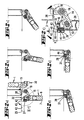
- FIGS. 2a to 2f show a section according to FIG Line II-II in Fig. 1, wherein the subfigures 2a to 2e describe different opening positions of the cargo door 1 and the subfigure 2f is an enlarged detail to Fig. 2a reproduces.
- a cam 32 is shown, which as extruded profile is formed and with a first T-shaped extension 33 in a first groove 34 and with a in Fig. 4 illustrated L-shaped second extension 35 in a second hollow groove 36 of the hinge-side profile 20 is held.
- the cam 32 extends at each the luggage compartment doors 1 only in a longitudinal section below of the lowest hinge 13.
- the inner wall 7 of the Load compartment door 1 a sealing wall 37 for sealing interaction with a Gegenwandung 38, which at the End face 18 of the side wall 3 is formed. in the illustrated embodiment is at the sealing wall 37 around a surface of a rubber seal 39, which on the inner wall 7 in a groove 40th by means of a T-shaped extension 41 in a form-fitting manner is attached.
- the on the hinge-side end wall. 9 attached cam 32 is for abutment against a contact surface 42 of the box body 2 determines which in shown embodiment on the front side 25 of the Bottom 5 of the box body 2 is provided.
- the cam 32 has an edge surface 43, with which he in a vertical to the hinge-side end wall 10 Direction over the hinge-side end wall 10 protrudes.
- the projection of the edge surface is in Fig. 2f with marked H.
- the cam 32 has continue the cargo space in the closed position of the Cargo door facing inner surface 44, which in a peripheral edge 45 merges into the edge surface 43. It it is clear that the edge surface 43, starting from the peripheral edge 45 under at least partial coverage of the hinge-side end wall 10 extends.
- the inner surface 44 is vertical to the inner wall 7 of the cargo door 1 via the Inner wall 7 forth.
- the assigned supernatant is in Fig. 2f marked with the reference symbol B.
- FIG. 2a to Fig. 2e are with ascending letter sequence various positions of the cargo door 1 shown during a closing process.
- Fig. 2a is initially an open position with dashed lines described the cargo door, in which the cargo door 1 with respect to its closing position by 270 ° is angled and substantially parallel to the Sidewall 3 is aligned.
- Fig. 2a is solid Lines on the other hand by 180 ° in the direction Direction of the cargo door twisted to the closed position 1 shown. It is clear that until reaching this pivotal position an exclusive Rotation of the hinge around the load compartment side Rotary axis 16 has taken place.
- the responsible connections becomes refer to the following description of FIG. 3. In the illustrated in Fig.
- Pivot position of the cargo door 1 is this in oriented substantially perpendicular to the closing position, and the cam 32 enters with its edge surface 43 in the region of the peripheral edge 45 in contact with the contact surface 42 of the box body 2.
- an articulated and side-shifting support the load compartment door 1 opposite the box body 2 which in conjunction with the axes of rotation 15, 16 a movable three-jointed forms.
- the system remains the Cam 32 at least at a slight pressure of the cargo door 1 against the box body 2 during the rest Closing movement until reaching the closing position the trunk door 1 received.
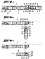
- FIG. 3 describes in the subfigures 3a to 3e a Partial section along the line III-III in Fig. 1, while Fig. 3f shows an enlarged detail of Fig. 3a.
- FIGS. 3a to 3e relate to FIG which are indexed with respective lower case letters Unterfiguren 2, or to the illustrated therein Swiveling positions of the load compartment door 1.
- axle beam 46 is arranged, which in a cross section is formed out of round and which on a door side mounted spring element 47 abuts.
- the axle body 46 a substantially rectangular cross-section with rounded narrow sides, which in smaller Turn radii into the long sides.
- the spring element 47 is designed as a flat spring, which with a flat side, which is in a perpendicular to the plane of the drawing aligned plane extends to the axle body 46 is present.
- the spring element 47 within the cargo door 1 at two ends 50, 51 attached. This is due to a clamping of the Spring element 47 between each a material projection 52, 53 and a housing web 54, 55 in one edge-side interior 56 of the hinge-side profile 20 realized.
- the axle body 46 inside the hinge side Profile 20 is directed to EP-A2 0 698 515. Out Figs.
- this is a pivoting of the luggage compartment door 1, starting from the dashed line position, such as outlined above, first to an exclusive, but at least to a predominant twisting of the Hinge member 14 to the loading space side axis of rotation 14th lead, until the cam 32 in contact with the contact surface 42 of the box body 2 occurs and in the likewise previously explained way a clear leadership of Cargo door in another closing movement allows.
- This further movement is in the subfigures 3b to 3e in different pivoting positions of Load compartment door 1 shown.
- the non-circular cross section of the axle body 46 at which the longitudinal sides 49 of the cross section substantially parallel to a connecting line between the Rotary axes 15, 16 run, are also other orientations conceivable in relation to this connecting line in particular rotated by 90 ° in the plane of the drawing Orientation in which the long sides 49 of the non-round Cross section in the plane lying in drawing Cutting plane at right angles to the connection axis between the axes of rotation 15, 16 run.
- an orientation of the non-round Cross-section conceivable, in which in one of Fig. 3a shown opening position of the cargo door a 270 ° minimum deflection of the spring element 47 is caused by the axle body 46, so that a quasi-stable equilibrium position of the cargo door is reached in the open position.
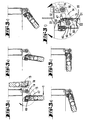
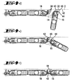
- Fig. 4 shows a partial section through a cargo door 1, which with a hinge 13, the hinge members 14, at a further cargo door 1 'articulated is connected.
- the load compartment door 1 ' is provided with a hinge members 14 'having hinge 13' on a not shown box body of a truck hinged.
- the luggage compartment doors 1, 1 ' are their Main directions of extension in a common, too the outer contour of the box body 2 parallel alignment.
- Such an arrangement of hinged together connected load-compartment doors 1, 1 ' is also called one several door panels formed cargo door.
- the load compartment door 1 at the the cargo door 1 'facing edge Profile 20 on which a cam 32 is attached with respect to the cross section Design of the cam and its attachment to the Profile 20 to the explanations related to the Figures 1 to 3 is referenced.
- the edge surface 43 of the cam 32 at the same time as a sealing wall 37th for sealing cooperation with a counter wall 38 of the box body 2 is formed or serves.
- FIG. 4a describes the closing position of the cargo compartment doors 1, 1 ', in which the edge surface 43 sealingly with the Gegenwandung 38 cooperates.
- FIG. 4c illustrate two different pivot positions the load compartment door 1 opposite the load compartment door 1 '
- Figures 4d to 4f illustrate various Pivot positions of the cargo door 1 during a subsequent Closing movement.
- the back wall 38 is at a seal 57 formed, which in the longitudinal direction of a End wall 58 of an edge-side profile 20 of the cargo door 1 'extends.
- the load compartment door 1 'with the trained therein coupleswandung 38 with respect to the load compartment door 1 as considered the box body 2 associated.
- the cam 32 extends in contrast to the embodiment shown in Figures 1 to 3 in Fig.
Landscapes
- Engineering & Computer Science (AREA)
- Mechanical Engineering (AREA)
- Closing And Opening Devices For Wings, And Checks For Wings (AREA)
- Hinge Accessories (AREA)
- Hinges (AREA)
- Lubricants (AREA)
- Glass Compositions (AREA)
- Devices For Use In Laboratory Experiments (AREA)
- Air Bags (AREA)
Description
- Fig. 1
- in Draufsicht zwei benachbarte Laderaumtüren nach der Erfindung,
- Fig. 2
- einen Teilschnitt gemäß der Linie II-II in Fig. 1, wobei die Teilfiguren 2a bis 2e verschiedene Öffnungspositionen der Laderaumtür betreffen und wobei Fig. 2f eine Ausschnittsvergrößerung zu Figur 2a wiedergibt,
- Fig. 3
- einen Teilschnitt gemäß der Linie III-III in Fig. 1, wobei die Unterfiguren 3a bis 3e verschiedene Öffnungspositionen der Laderaumtür betreffen und die Unterfigur 3f eine Ausschnittsvergrößerung zu Fig. 3a wiedergibt,
- Fig. 4
- einen Teilschnitt durch eine abweichende, zweiflügelige Laderaumtür nach der Erfindung, wobei die Unterfiguren 4a bis 4f verschiedene Öffnungspositionen eines Türflügels betreffen.
Claims (15)
- Laderaumtür (1) mit einer dem Laderaum in Verschlussposition zugewandten Innenwand (7), mit einer Außenwand (8) und mit Stirnwänden (9,10,11,12), wobei an dem Außenrand der Laderaumtür (1) ein Scharnier (13) mit einem um zwei Drehachsen drehbaren Scharnierglied (14) angeordnet ist und die Laderaumtür (1) eine Dichtwandung (37) zur dichtenden Zusammenwirkung mit einer Gegenwandung aufweist, dadurch gekennzeichnet, dass an der scharnierseitigen Stirnwand (10) ein Nocken (32) für eine Anlage an einer Anlagefläche (42) des Kastenaufbaus (2) ausgebildet ist, welcher mit einer Randfläche (43) in einer zu der scharnierseitigen Stirnwand (10) senkrechten Richtung über die scharnierseitige Stirnwand (10) übersteht.
- Laderaumrür nach Anspruch 1, dadurch gekennzeichnet, dass der Nocken (32) eine dem Laderaum (2) in Verschlussposition zugewandte Innenfläche (44) aufweist, welche in einer Randkante (45) in die Randfläche (43) übergeht, und dass sich die Randfläche (43) ausgehend von der Randkante (45) unter zumindest teilweiser Überdeckung der scharnierseitigen Stirnwand (10) erstreckt.
- Laderaumtür nach Anspruch 2, dadurch gekennzeichnet, dass die Innenfläche (44) senkrecht zu der Innenwand (7) über die Innenwand (7) hervorsteht.
- Laderaumtür nach einem der vorhergehenden Ansprüche, dadurch gekennzeichnet, dass der Nocken (32) in Haupterstreckung der scharnierseitigen Stirnwand (10) in einem Endbereich dieser Stirnwand (10) angeordnet ist.
- Laderaumtür nach einem der Ansprüche 2 bis 4, dadurch gekennzeichnet, dass die Dichtwandung (37) in Verschlussposition mit der Innenfläche (44) des Nockens (32) in einer gemeinsamen Ebene angeordnet ist.
- Laderaumtür nach einem der Ansprüche 1 bis 4, dadurch gekennzeichnet, dass die Randfläche (43) als Dichtwandung (37) ausgebildet ist.
- Laderaumtür nach einem der vorhergehenden Ansprüche, dadurch gekennzeichnet, dass der Nocken (32) als Strangprofil ausgebildet ist.
- Laderaumtür nach einem der vorhergehenden Ansprüche, dadurch gekennzeichnet, dass der Nocken (32) mit einem Randprofil (20) der Laderaumtür (1) verbunden ist.
- Laderaumtür nach einem der vorhergehenden Ansprüche, dadurch gekennzeichnet, dass der Nocken (32) aus einem Kunststoff hergestellt ist.
- Laderaumtür nach einem der Ansprüche 2 bis 9, dadurch gekennzeichnet, dass das Scharnierglied (14) den Außenrand der Laderaumtür (1) mit einer der beiden Drehachsen (15, 16) durchsetzt, und dass die Innenfläche (44) in einem die Verschlussposition einschließenden Drehwinkelbereich der Laderaumtür (1) in Projektion auf die von den Drehachsen (15,16) bestimmte Ebene zumindest bereichsweise zwischen den Drehachsen (15, 16) angeordnet ist.
- Laderaumtür (1), nach einem der Ansprüche 1 bis 10 wobei bezüglich der türseitigen Drehachse ein drehsteif mit dem Schamierglied verbundener Achskörper angeordnet ist, welcher in einem Querschnitt unrund ausgebildet ist, dadurch gekennzeichnet, dass der Achskörper (46) an einem türseitig befestigten Federelement (47) anliegt, welches durch den Achskörper (46) eine von dem Drehwinkel zwischen dem Achskörper (46) und der Laderaumtür (1) abhängige Verformung erfährt.
- Laderaumtür nach Anspruch 11, dadurch gekennzeichnet, dass das Scharnierglied (14) den Außenrand der Laderaumtür (1) durchsetzt und dass das Federelement (47) als Flachfeder ausgebildet ist, welche mit einer Flachseite an dem Achskörper (46) anliegt.
- Laderaumtür nach einem der Ansprüche 11 oder 12, dadurch gekennzeichnet, dass das Federelement (47) innerhalb der Laderaumtür (1) an zwei Enden befestigt ist.
- Laderaumtür nach einem der Ansprüche 11 bis 13, dadurch gekennzeichnet, dass der unrunde Querschnitt des Achskörpers (46) so zu dem Scharnierglied (14) ausgerichtet ist, dass er in Verschlussposition der Laderaumtür (1) eine minimale Verformung des Federelements (47) bewirkt und/oder dass er in einer Öffnungsposition der Laderaumtür (1) eine maximale Verformung des Federelements (47) bewirkt.
- Laderaumtür nach einem der Ansprüche 11 bis 14, dadurch gekennzeichnet, dass bei einem von der Öffnungsposition ausgehenden Verschwenken der Laderaumtür (1) keine Verdrehung des Achskörpers (46) relativ zu der Laderaumtür (1) erfolgt, bis der Nocken (32) in eine Anlage zu dem Kastenaufbau (2) tritt.
Priority Applications (1)
| Application Number | Priority Date | Filing Date | Title |
|---|---|---|---|
| SI9930242T SI0976594T1 (en) | 1998-07-27 | 1999-07-24 | Cargo door |
Applications Claiming Priority (2)
| Application Number | Priority Date | Filing Date | Title |
|---|---|---|---|
| DE29813289U DE29813289U1 (de) | 1998-07-27 | 1998-07-27 | Laderaumtür |
| DE29813289U | 1998-07-27 |
Publications (2)
| Publication Number | Publication Date |
|---|---|
| EP0976594A1 EP0976594A1 (de) | 2000-02-02 |
| EP0976594B1 true EP0976594B1 (de) | 2003-01-08 |
Family
ID=8060391
Family Applications (1)
| Application Number | Title | Priority Date | Filing Date |
|---|---|---|---|
| EP99114511A Expired - Lifetime EP0976594B1 (de) | 1998-07-27 | 1999-07-24 | Laderaumtür |
Country Status (6)
| Country | Link |
|---|---|
| EP (1) | EP0976594B1 (de) |
| AT (1) | ATE230685T1 (de) |
| DE (2) | DE29813289U1 (de) |
| DK (1) | DK0976594T3 (de) |
| ES (1) | ES2191391T3 (de) |
| SI (1) | SI0976594T1 (de) |
Cited By (1)
| Publication number | Priority date | Publication date | Assignee | Title |
|---|---|---|---|---|
| FR2859675A1 (fr) * | 2003-09-16 | 2005-03-18 | Linde Ag | Chariot transporteur comportant une ouverture laterale du chassis equipe d'une porte a double charniere |
Families Citing this family (3)
| Publication number | Priority date | Publication date | Assignee | Title |
|---|---|---|---|---|
| DE20008656U1 (de) | 2000-05-13 | 2001-09-27 | PWP S.A., Payerne, Waadt | Schüttgutabweiser |
| FR2843338B1 (fr) * | 2002-08-08 | 2004-10-29 | Boyriven Roby | Porte pour espace de chargement et vehicule industriel pourvu d'au moins une telle porte |
| DE102006044712A1 (de) * | 2006-09-20 | 2008-04-03 | Pwp S.A., Payerne | Tür für den Kastenaufbau eines Kraftfahrzeugs |
Family Cites Families (4)
| Publication number | Priority date | Publication date | Assignee | Title |
|---|---|---|---|---|
| US4403452A (en) * | 1981-06-25 | 1983-09-13 | Met-L-Wood Corporation | Hardware attaching means for panel structures |
| DE9110532U1 (de) * | 1990-09-25 | 1991-10-10 | Helmut Weisbender GmbH & Co KG, 5430 Montabaur | Vorrichtung zum Verstellen eines über ein oder mehrere Scharniere mit einem feststehenden Teil verbundenen beweglichen Teils |
| DE9419874U1 (de) * | 1994-08-26 | 1996-01-04 | PWP S.A., Payerne, Waadt | Laderaumtür für z.B. einen Kastenaufbau eines LKW |
| IT1281858B1 (it) * | 1995-03-31 | 1998-03-03 | Aghito Dino Spa | Sistema di chiusura per porte dei vani di carico dei veicoli comprendente cerniere, perni di rotazione, aste di chiusura |
-
1998
- 1998-07-27 DE DE29813289U patent/DE29813289U1/de not_active Expired - Lifetime
-
1999
- 1999-07-24 EP EP99114511A patent/EP0976594B1/de not_active Expired - Lifetime
- 1999-07-24 SI SI9930242T patent/SI0976594T1/xx unknown
- 1999-07-24 DE DE59903956T patent/DE59903956D1/de not_active Expired - Fee Related
- 1999-07-24 AT AT99114511T patent/ATE230685T1/de not_active IP Right Cessation
- 1999-07-24 ES ES99114511T patent/ES2191391T3/es not_active Expired - Lifetime
- 1999-07-24 DK DK99114511T patent/DK0976594T3/da active
Cited By (1)
| Publication number | Priority date | Publication date | Assignee | Title |
|---|---|---|---|---|
| FR2859675A1 (fr) * | 2003-09-16 | 2005-03-18 | Linde Ag | Chariot transporteur comportant une ouverture laterale du chassis equipe d'une porte a double charniere |
Also Published As
| Publication number | Publication date |
|---|---|
| DE59903956D1 (de) | 2003-02-13 |
| EP0976594A1 (de) | 2000-02-02 |
| DE29813289U1 (de) | 1999-12-02 |
| ATE230685T1 (de) | 2003-01-15 |
| ES2191391T3 (es) | 2003-09-01 |
| DK0976594T3 (da) | 2003-04-28 |
| SI0976594T1 (en) | 2003-08-31 |
Similar Documents
| Publication | Publication Date | Title |
|---|---|---|
| EP0646690B1 (de) | Stütze zum Halten eines Verschlusselementes | |
| EP3417134B1 (de) | Beschlaganordnung zur anbindung eines schieb- und kippbaren flügels | |
| WO1990005827A1 (de) | In türen und wände einsetzbare durchreichevorrichtung | |
| DE68903724T2 (de) | Beschlag fuer tuer, fenster oder dergleichen. | |
| DE1630497A1 (de) | Tuer-Feststellvorrichtung | |
| EP1165917B1 (de) | Verstellvorrichtung für ausstellfenster | |
| EP1090204A1 (de) | Verschlusseinrichtung für fenster, türen od.dgl. öffnungen | |
| EP0021080B1 (de) | Hebe-Schiebe-Kipp-Tür oder -Fenster | |
| DE102007056853A1 (de) | Feststeller für das Verschlusselement einer Kfz-Hecköffnung | |
| DE2702470B2 (de) | Feststellvorichtung für eine Tür, insbesondere an Kraftfahrzeugen | |
| WO2024115762A1 (de) | Teilbares türflügelsegment | |
| EP0976594B1 (de) | Laderaumtür | |
| DE2653106C2 (de) | Klappenhalter | |
| DE19833168B4 (de) | Griffbeschlag für eine Kfz-Schiebetür | |
| DE102007024572B4 (de) | Scharnier für eine Kraftfahrzeugtür | |
| DE2211523A1 (de) | Schliesstueck fuer metall- oder kunststoff-fenster oder -tueren | |
| DE2850470C2 (de) | Zu öffnende Klappe, insbesondere Tankklappe | |
| DE2942136C2 (de) | Vorrichtung zum Feststellen einer Schwenktür eines Kraftfahrzeuges od. dgl. in ihrer Offenstellung | |
| EP2013045A1 (de) | Hubfenster | |
| DE3231638C2 (de) | Scheibenwischerelement mit einem Scheibenwischerarm, der der Wirkung einer Druckfeder unterliegt | |
| EP0628692B1 (de) | Lagerelement eines oberen Drehlagers für einen wenigstens drehbar gelagerten Flügel eines Fensters, einer Tür oder dergleichen | |
| EP1862631A2 (de) | Antriebsanordnung zur motorischen Verstellung eines Verschlußelements eines Kraftfahrzeugs | |
| DE10222998B4 (de) | Rückwandtür mit Türsicherungselementen für ein Lastfahrzeug | |
| EP4446535B1 (de) | Integrierte seitliche abdicht- und verriegelungsvorrichtung | |
| EP1231345B1 (de) | Gesteuerte Verriegelungsvorrichtung und Eckumlenkung |
Legal Events
| Date | Code | Title | Description |
|---|---|---|---|
| PUAI | Public reference made under article 153(3) epc to a published international application that has entered the european phase |
Free format text: ORIGINAL CODE: 0009012 |
|
| AK | Designated contracting states |
Kind code of ref document: A1 Designated state(s): AT BE CH CY DE DK ES FI FR GB GR IE IT LI LU MC NL PT SE |
|
| AX | Request for extension of the european patent |
Free format text: AL;LT;LV;MK;RO;SI |
|
| 17P | Request for examination filed |
Effective date: 20000726 |
|
| AKX | Designation fees paid |
Free format text: AT BE CH CY DE DK ES FI FR GB GR IE IT LI LU MC NL PT SE |
|
| AXX | Extension fees paid |
Free format text: SI PAYMENT 20000726 |
|
| 17Q | First examination report despatched |
Effective date: 20020219 |
|
| GRAH | Despatch of communication of intention to grant a patent |
Free format text: ORIGINAL CODE: EPIDOS IGRA |
|
| GRAH | Despatch of communication of intention to grant a patent |
Free format text: ORIGINAL CODE: EPIDOS IGRA |
|
| GRAA | (expected) grant |
Free format text: ORIGINAL CODE: 0009210 |
|
| AK | Designated contracting states |
Kind code of ref document: B1 Designated state(s): AT BE CH CY DE DK ES FI FR GB GR IE IT LI LU MC NL PT SE |
|
| AX | Request for extension of the european patent |
Free format text: SI PAYMENT 20000726 |
|
| PG25 | Lapsed in a contracting state [announced via postgrant information from national office to epo] |
Ref country code: GR Free format text: LAPSE BECAUSE OF FAILURE TO SUBMIT A TRANSLATION OF THE DESCRIPTION OR TO PAY THE FEE WITHIN THE PRESCRIBED TIME-LIMIT Effective date: 20030108 |
|
| REF | Corresponds to: |
Ref document number: 230685 Country of ref document: AT Date of ref document: 20030115 Kind code of ref document: T |
|
| REG | Reference to a national code |
Ref country code: GB Ref legal event code: FG4D Free format text: NOT ENGLISH |
|
| REG | Reference to a national code |
Ref country code: CH Ref legal event code: EP |
|
| REG | Reference to a national code |
Ref country code: IE Ref legal event code: FG4D Free format text: GERMAN |
|
| REF | Corresponds to: |
Ref document number: 59903956 Country of ref document: DE Date of ref document: 20030213 Kind code of ref document: P |
|
| REG | Reference to a national code |
Ref country code: CH Ref legal event code: NV Representative=s name: R. A. EGLI & CO. PATENTANWAELTE |
|
| REG | Reference to a national code |
Ref country code: SE Ref legal event code: TRGR |
|
| REG | Reference to a national code |
Ref country code: DK Ref legal event code: T3 |
|
| GBT | Gb: translation of ep patent filed (gb section 77(6)(a)/1977) |
Effective date: 20030509 |
|
| PG25 | Lapsed in a contracting state [announced via postgrant information from national office to epo] |
Ref country code: CY Free format text: LAPSE BECAUSE OF FAILURE TO SUBMIT A TRANSLATION OF THE DESCRIPTION OR TO PAY THE FEE WITHIN THE PRESCRIBED TIME-LIMIT Effective date: 20030724 |
|
| PG25 | Lapsed in a contracting state [announced via postgrant information from national office to epo] |
Ref country code: MC Free format text: LAPSE BECAUSE OF NON-PAYMENT OF DUE FEES Effective date: 20030731 |
|
| ET | Fr: translation filed | ||
| REG | Reference to a national code |
Ref country code: ES Ref legal event code: FG2A Ref document number: 2191391 Country of ref document: ES Kind code of ref document: T3 |
|
| PLBE | No opposition filed within time limit |
Free format text: ORIGINAL CODE: 0009261 |
|
| STAA | Information on the status of an ep patent application or granted ep patent |
Free format text: STATUS: NO OPPOSITION FILED WITHIN TIME LIMIT |
|
| 26N | No opposition filed |
Effective date: 20031009 |
|
| REG | Reference to a national code |
Ref country code: SI Ref legal event code: IF |
|
| PGFP | Annual fee paid to national office [announced via postgrant information from national office to epo] |
Ref country code: IE Payment date: 20090616 Year of fee payment: 11 |
|
| PGFP | Annual fee paid to national office [announced via postgrant information from national office to epo] |
Ref country code: PT Payment date: 20090619 Year of fee payment: 11 |
|
| PGFP | Annual fee paid to national office [announced via postgrant information from national office to epo] |
Ref country code: FR Payment date: 20090723 Year of fee payment: 11 Ref country code: ES Payment date: 20090724 Year of fee payment: 11 Ref country code: DK Payment date: 20090729 Year of fee payment: 11 |
|
| PGFP | Annual fee paid to national office [announced via postgrant information from national office to epo] |
Ref country code: SE Payment date: 20090730 Year of fee payment: 11 Ref country code: NL Payment date: 20090724 Year of fee payment: 11 Ref country code: LU Payment date: 20090723 Year of fee payment: 11 Ref country code: GB Payment date: 20090728 Year of fee payment: 11 Ref country code: FI Payment date: 20090727 Year of fee payment: 11 Ref country code: DE Payment date: 20090811 Year of fee payment: 11 Ref country code: CH Payment date: 20090728 Year of fee payment: 11 Ref country code: AT Payment date: 20090724 Year of fee payment: 11 |
|
| PGFP | Annual fee paid to national office [announced via postgrant information from national office to epo] |
Ref country code: BE Payment date: 20090727 Year of fee payment: 11 |
|
| PGFP | Annual fee paid to national office [announced via postgrant information from national office to epo] |
Ref country code: IT Payment date: 20090729 Year of fee payment: 11 |
|
| BERE | Be: lapsed |
Owner name: S.A. *PWP Effective date: 20100731 |
|
| REG | Reference to a national code |
Ref country code: PT Ref legal event code: MM4A Free format text: LAPSE DUE TO NON-PAYMENT OF FEES Effective date: 20110124 |
|
| REG | Reference to a national code |
Ref country code: NL Ref legal event code: V1 Effective date: 20110201 |
|
| REG | Reference to a national code |
Ref country code: CH Ref legal event code: PL |
|
| GBPC | Gb: european patent ceased through non-payment of renewal fee |
Effective date: 20100724 |
|
| REG | Reference to a national code |
Ref country code: FR Ref legal event code: ST Effective date: 20110331 |
|
| REG | Reference to a national code |
Ref country code: IE Ref legal event code: MM4A |
|
| PG25 | Lapsed in a contracting state [announced via postgrant information from national office to epo] |
Ref country code: DE Free format text: LAPSE BECAUSE OF NON-PAYMENT OF DUE FEES Effective date: 20110201 Ref country code: CH Free format text: LAPSE BECAUSE OF NON-PAYMENT OF DUE FEES Effective date: 20100731 Ref country code: LI Free format text: LAPSE BECAUSE OF NON-PAYMENT OF DUE FEES Effective date: 20100731 |
|
| REG | Reference to a national code |
Ref country code: SI Ref legal event code: KO00 Effective date: 20110228 |
|
| REG | Reference to a national code |
Ref country code: DE Ref legal event code: R119 Ref document number: 59903956 Country of ref document: DE Effective date: 20110201 |
|
| PG25 | Lapsed in a contracting state [announced via postgrant information from national office to epo] |
Ref country code: IT Free format text: LAPSE BECAUSE OF NON-PAYMENT OF DUE FEES Effective date: 20100724 Ref country code: FR Free format text: LAPSE BECAUSE OF NON-PAYMENT OF DUE FEES Effective date: 20100802 Ref country code: AT Free format text: LAPSE BECAUSE OF NON-PAYMENT OF DUE FEES Effective date: 20100724 Ref country code: NL Free format text: LAPSE BECAUSE OF NON-PAYMENT OF DUE FEES Effective date: 20110201 Ref country code: PT Free format text: LAPSE BECAUSE OF NON-PAYMENT OF DUE FEES Effective date: 20110124 Ref country code: FI Free format text: LAPSE BECAUSE OF NON-PAYMENT OF DUE FEES Effective date: 20100724 |
|
| PG25 | Lapsed in a contracting state [announced via postgrant information from national office to epo] |
Ref country code: BE Free format text: LAPSE BECAUSE OF NON-PAYMENT OF DUE FEES Effective date: 20100731 |
|
| PG25 | Lapsed in a contracting state [announced via postgrant information from national office to epo] |
Ref country code: GB Free format text: LAPSE BECAUSE OF NON-PAYMENT OF DUE FEES Effective date: 20100724 Ref country code: IE Free format text: LAPSE BECAUSE OF NON-PAYMENT OF DUE FEES Effective date: 20100726 |
|
| REG | Reference to a national code |
Ref country code: ES Ref legal event code: FD2A Effective date: 20110818 |
|
| REG | Reference to a national code |
Ref country code: DK Ref legal event code: EBP |
|
| PG25 | Lapsed in a contracting state [announced via postgrant information from national office to epo] |
Ref country code: ES Free format text: LAPSE BECAUSE OF NON-PAYMENT OF DUE FEES Effective date: 20100725 |
|
| PG25 | Lapsed in a contracting state [announced via postgrant information from national office to epo] |
Ref country code: DK Free format text: LAPSE BECAUSE OF NON-PAYMENT OF DUE FEES Effective date: 20100802 |
|
| PG25 | Lapsed in a contracting state [announced via postgrant information from national office to epo] |
Ref country code: SE Free format text: LAPSE BECAUSE OF NON-PAYMENT OF DUE FEES Effective date: 20100725 Ref country code: LU Free format text: LAPSE BECAUSE OF NON-PAYMENT OF DUE FEES Effective date: 20100724 |