EP0975164A2 - Bildermittlungssystem- und Verfahren - Google Patents
Bildermittlungssystem- und Verfahren Download PDFInfo
- Publication number
- EP0975164A2 EP0975164A2 EP99305776A EP99305776A EP0975164A2 EP 0975164 A2 EP0975164 A2 EP 0975164A2 EP 99305776 A EP99305776 A EP 99305776A EP 99305776 A EP99305776 A EP 99305776A EP 0975164 A2 EP0975164 A2 EP 0975164A2
- Authority
- EP
- European Patent Office
- Prior art keywords
- image signals
- speed
- recording
- recording medium
- outputting
- Prior art date
- Legal status (The legal status is an assumption and is not a legal conclusion. Google has not performed a legal analysis and makes no representation as to the accuracy of the status listed.)
- Granted
Links
Images


Classifications
-
- H—ELECTRICITY
- H04—ELECTRIC COMMUNICATION TECHNIQUE
- H04N—PICTORIAL COMMUNICATION, e.g. TELEVISION
- H04N5/00—Details of television systems
- H04N5/76—Television signal recording
- H04N5/765—Interface circuits between an apparatus for recording and another apparatus
- H04N5/77—Interface circuits between an apparatus for recording and another apparatus between a recording apparatus and a television camera
-
- H—ELECTRICITY
- H04—ELECTRIC COMMUNICATION TECHNIQUE
- H04N—PICTORIAL COMMUNICATION, e.g. TELEVISION
- H04N5/00—Details of television systems
- H04N5/76—Television signal recording
- H04N5/78—Television signal recording using magnetic recording
- H04N5/781—Television signal recording using magnetic recording on disks or drums
-
- H—ELECTRICITY
- H04—ELECTRIC COMMUNICATION TECHNIQUE
- H04N—PICTORIAL COMMUNICATION, e.g. TELEVISION
- H04N9/00—Details of colour television systems
- H04N9/79—Processing of colour television signals in connection with recording
- H04N9/80—Transformation of the television signal for recording, e.g. modulation, frequency changing; Inverse transformation for playback
- H04N9/804—Transformation of the television signal for recording, e.g. modulation, frequency changing; Inverse transformation for playback involving pulse code modulation of the colour picture signal components
- H04N9/8042—Transformation of the television signal for recording, e.g. modulation, frequency changing; Inverse transformation for playback involving pulse code modulation of the colour picture signal components involving data reduction
Definitions
- This invention relates to an imaging system and method.
- the images aired in, for example, a news program by a telecasting station are those obtained on editing the image and the speech recorded on plural television cameras having enclosed video tape recorders.
- the images etc edited in this manner are recorded on a video tape and reproduced in the course of telecasting.
- the telecasting station makes live relay broadcasting of a sports game
- plural cameras are used simultaneously and selectively depending on the progress of the game to send the images and the speech to respective homes, while the images etc are recorded on a video tape recorder.
- the scene is sometimes re-played at a slow speed or at an ordinary speed in order to re-transmit the scene to the viewers.
- the video tape recorder is designed to be run at a speed thrice the usual speed to record the video signals transmitted from the camera.
- the tape recorder runs the magnetic head at the usual speed to reproduce the video signals. This assures slow reproduction with a smooth movement and a high picture quality.
- the video tape recorder since the video tape recorder usually has only one recording head, it is not possible to reproduce previously recorded images and simultaneously to record images or speech.
- the video tape recorder if desired to record images shot by a camera and simultaneously reproduce an optional scene, it is necessary to record the images simultaneously on plural video tape recorders, to use one of the video tape recorders as a video tape recorder dedicated to recording, and to use the remaining video tape recorders for replay. This means that it is a highly pains-taking operation to record images and to reproduce optional scenes simultaneously.
- the present invention provides an imaging system including imaging means for outputting image signals shot of an object, speed changing means for changing the image signals outputted by the imaging means at a first speed into signals of a second speed to output the image signals of the second speed and recording/reproducing means.
- the recording/reproducing means includes a plurality of input/output processing means to which are inputted the signals of the second speed outputted by the speed changing means and which output the reproduced image signals to outside, and a non-linear accessible recording medium for recording the image signals.
- the recording/reproducing means has access to the recording medium only within an allocated time slot to output the image signals inputted from the speed changing means to the recording medium.
- the recording/reproducing means has access to the recording medium only within the allocated time slot to input the reproduced image signals from the recording medium.
- the present invention provides a recording/reproducing method for recording/reproducing as-shot image signals including a first step of outputting image signals as shot by imaging means at a first speed, a second step of converting the image signals at the first speed, outputted at the first step, into those at a second speed, and for outputting the converted image signals, a third step of inputting the image signals outputted at the second step and outputting the input image signals to a non-linear accessible recording medium only within an allocated time slot, a fourth step of recording the image signals outputted at the third step on the recording medium, a fifth step of reproducing the image signals recorded at the fourth step on the recording medium and a sixth step of outputting the image signals reproduced at the fifth step only within the allocated time slot to outside at the second speed in the order of the image signals of the first speed.
- the present invention provides a recording method for recording as-shot image signals including a first step of outputting image signals as shot by imaging means at a first speed, a second step of converting the image signals at the first speed, outputted at the first step, into those at a second speed, and for outputting the converted image signals, a third step of outputting the input image signals to a non-linear accessible recording medium only within an allocated time slot; and a fourth step of recording the image signals outputted at the third step on the recording medium.
- Embodiments of the present invention provide an imaging system in which it is possible to record images from a camera and to revert to an optional scene to reproduce an image corresponding to the scene.
- a desired scene of image signals as shot can be reproduced at the same time as image signals are recorded.
- image signals from imaging means can be recorded on recording means, while reversion may be made to an optional scene to read out and reproduce picture signals of the scene.
- image signals of large capacity can be compressed and recorded in this state on a server, while reversion may be made to an optional scene to read out and reproduce picture signals of the scene.
- Fig. 1 is a block diagram showing the structure of a camera system in accordance with an embodiment of the present invention.
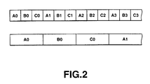
- Fig.2 illustrates the flow of CCU image signals of the camera system.
- Fig.3 is a block diagram showing the structure of a video server of the camera system.
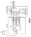
- Fig.4 is a block diagram showing the structure of another camera system in accordance with an embodiment of the present invention.
- Fig.5 is a block diagram showing the structure of yet another camera system in accordance with an embodiment of the present invention.
- a camera system 1 in accordance with a first embodiment is configured as shown for example in Fig.1.
- the camera system 1 includes a camera device 10 for shooting an object, a camera control unit (CCU) 20 for processing image signals from the camera device 10 in a pre-set fashion, and a video server 30 for storing the image signals from the CCU 20.
- CCU camera control unit
- the camera device 10 is a high-speed camera and outputs image signals at a speed thrice the usual speed (90 frames per second) to furnish the output image signals to the CCU 20.
- the camera device 10 generates three color signals, responsive to the imaging light of the object, and converts the tri-color signals into luminance and chrominance signals which are outputted as image signals. It is noted that the processing as from the CCU 20 is the same for the luminance and chrominance signals. Thus, in Fig.1, only a signal line routing one of the luminance or the chrominance signals from the camera device 10 to the CCU 20 is shown, while other signal lines are not shown.
- the CCU 20 performs pre-set signal processing, such as gamma correction or knee processing, on image signals form the camera device 10, and also has the rate converting function.
- the CCU 20 includes an analog/digital (A/D) converter 21 for digitizing image signals, a data distributor 22 for outputting image signals from the A/D converter 21 via pre-set terminal, and a first memory 23, a second memory 14 and a third memory 25 for storing the distributed image signals.
- the CCU20 also includes a controller 26 for controlling the switching by the data distributor 22.
- the A/D converter 21 digitizes the image signals, processed in a pre-set fashion, and routes the image signals to the data distributor 22.
- the data distributor 22 includes a switch 22a for selecting one of the terminals a, b or c.
- the picture signals supplied from the A/D converter 21 are outputted via terminals a, b or c.
- the controller 26 performs control to move a movable terminal of the switch 22a to the terminals a, b, c, a, b, c, ⁇ every 1/90 second. This connects the switch 22a to the terminals a, b and c every 1/30 period.
- Fig.2 shows an example of image signals outputted by the A/D converter 21.
- the image signals are fed to the data distributor 22 in the order of A0, B0, C0, A1, B1, C1, A2, B2, C2, ⁇ , where An, Bn and Cn, n being an integer not less than 0, denote image signals for one frame outputted during 1/90 second.
- the first memory 23, the second memory 24 and the third memory 25 are each comprised of a shift register.
- the data distributor 22 writes the image signals A0, B0, C0, A1, ⁇ in the first memory 23, second memory 24, third memory 24 and in the first memory 23, ⁇ , respectively. Stated differently, the data distributor 22 writes the image signals A0, A1, A2, A3, ⁇ in the first memory 23, while writing the image signals B0, B1, B2, B3, ⁇ in the second memory 25 and writing the image signals C0, C1, C2, C3, ⁇ in the third memory 25 every 1/30 second. The result is that image signals are read out at a rate of 30 frames per second.
- the CCU 20 processes the image signals, supplied from the camera device 10 at a rate thrice the usual rate, in a pre-set fashion, and distributes the image signals into three signal portions every 1/90 second by way of conversion to parallel signals.
- the image signals, thus converted into signals of the usual rate of 30 frames per second, are routed to the video server 30.
- the video server 30 is configured as shown in Fig.3. That is, the video server 30 is made up of an input/output processing unit 31 (31a to 31f), a RAID (Redundant Array of Inexpensive Discs) 32 (32a to 32e) and an MS 34.
- an input/output processing unit 31 31a to 31f
- a RAID Redundant Array of Inexpensive Discs
- an MS 34 MS 34.
- the input/output processing unit 31 compresses the image signals supplied from outside to route the compressed image signals to the RAID 32 over an input data bus 33a.
- the image memory 32 also expands the image signals read out from the RAID 32 to output the expanded image signals over an output data bus 33b.
- the RAID 32 is made up of plural hard disc drives (HDDs) such that it is able to record data by a certain magnetic head at the same time as it seeks another magnetic head to reproduce optional data.
- the video server 30 shown in Fig.1 shows the video server 30 of Fig.3 in a simplified fashion.
- the video server 30 includes plural input/output processing units 31 (31a, 31b, 31c, 31d, ⁇ ), plural RAIDs 32 (32a, 32b, ⁇ ) and a bus controller 34.
- the bus controller 34 controls time slots on the bus 33 provided in association with the numbers of the input/output processing units 31 and the RAIDs 32 to effect the recording/reproduction by the input/output processing unit 31 and by the RAID 32 simultaneously.
- the input/output processing unit 31a compresses image signals read out from the first memory 23, while the input/output processing unit 31b and the input/output processing unit 31c compress the image signals read out from the second memory 24 and from the third memory 25, respectively. These input/output processing units 31 send the compressed image signals over the bus 33 to the RAIDs 32a and 32b.
- the image signals distributed into three signal portions in the CPU 20 and converted to usual rate signals are respectively recorded in the RAIDs 32 of the video server 30.
- the video server 30 reads out the image signals recorded on the RAID 32 in the order of the original video frames to output the read-out signals via the input/output processing unit 31d. That is, the video server 30 reads out the image signals A0, B0, C0, A1, B1, C1, A2, B2, C2, ⁇ at the usual video rate and outputs the read-out signals after expansion by the input/output processing unit 31d.
- the video server 30 randomly stores the image signals, converted from the rate of 90 frames per second to 30 frames per second.
- the video server 30 reads out the image signals at a rate of 30 frames per second in the order of the original image signals by way of conversion to parallel signals. That is, the video server 30 outputs image signals for slow reproduction of smooth movement via input/output processing unit 31 d rather than outputting image signals of discretely located frames.
- An image of slow reproduction, obtained in this manner, is displayed on the monitor 40.
- the camera device 10 outputs the image signals at a rate thrice the usual rate.
- the present invention is, however, not limited to this configuration. That is, if the camera device 10 outputs image signals at a n-tupled rate, where n is a natural number, it suffices if the CCU 20 distributes the image signals into n signal portions to convert the image signals into image signals of the usual rate to output the resulting image signals of the usual rate. At this time, it suffices if the video server 30 stores the image signals in the RAID 32 and reads out the image signals from the RAID 32 for reproduction in the sequence of the original image signals. This assures slow motion reproduction at the 1/n speed.
- FIG.4 A second embodiment of the present invention is explained with reference to Fig.4 in which the camera system 1 is similar in structure to that of the first embodiment.
- the video server 30 randomly records the image signals in the RAID 32 on the frame basis. This renders it necessary for the video server 30 to have random access to the recording area of the RAID 32 at the time of reproduction.
- certain types of the HDD constituting the RAID 32 cannot read data unless the data are continuous to some extent.
- the preferred embodiment is designed to cope with this type of the HDD.
- the controller 26 of the CCU 20 changes over the state of the switch 22a every four frames of the video signals routed from the camera device 10 to the CCU 20.
- This causes the image signals A0, B0, C0, A1 to be collectively stored in the first memory 23, while causing the image signals B1, C1, A2, B2 to be collectively stored in the second memory 24 and causing the image signals C2, A3, B3, C3 to be collectively stored in the third memory 25.
- the image signals A4, B4, C4 and A5 then are stored in the first memory 23. These four frames of the image signals are collectively stored in this manner in the RAID 32.
- the video server 30 reads out the image signals from the RAID 32 in terms of the four frames as a unit. That is, since the video server 30 stores the image signals in terms of a pre-set sizeable volume as a unit, the magnetic head seek time can be shorter at the time of reproduction than if the image signals are randomly stored on the frame basis. This renders it possible to cope with the RAID 32 comprised of HDDs that cannot read out data unless the data is continuous to some extent.
- the present invention is naturally not limited to this configuration. Specifically, it is sufficient if the unit volume corresponds to the continuous data volume that can be read out by the HDDs constituting the RAID 32, such that the number of frames is not fixed at a special number of frames, such as five or six frames.
- FIG.5 A third embodiment of the present invention is explained with reference to Fig.5.
- the same reference numerals are used to depict the same circuits and detailed description is omitted for simplicity.
- the camera device 10 generates image signals, comprised of three prime color signals, responsive to the imaging light from an object, and routes these image signals to a CCU 20A.
- the camera device 10 is a camera for high-speed imaging adapted for outputting image signals at a rate of 90 frames per second, as in the first embodiment.
- the CCU 20A includes a demultiplexer 51 for demultiplexing the image signals, a buffer memory 52 (52R, 52G and 52B), an encoder 53 (53R, 53G and 52B) for compressing respective color signals, a buffer memory (54R, 54G and 54B) for outputting compressed color signals from the encoder 53 at a pre-set rate, a multiplexer 55 (55R, 55G, 55B) for multiplexing the respective compressed color signals, and a controller 56 for controlling the respective circuits of the CCU 20A.
- a demultiplexer 51 for demultiplexing the image signals
- a buffer memory 52 52R, 52G and 52B
- an encoder 53 53R, 53G and 52B
- a buffer memory 54R, 54G and 54B
- a controller 56 for controlling the respective circuits of the CCU 20A.
- the demultiplexer 51 demultiplexes the image signals supplied from the camera device 10 into red, green and blue signals, which then are routed to the buffer memories 52R, 52G and 52B, respectively.
- the image signals, inputted to the CCU 20A at a rate thrice the usual rate, are converted in this manner into signals of the usual rate which are routed to the respective encoders 53R, 53G and 53B.
- the encoders 53 53R, 53G and 53B are able to process the image signals of the usual input rate (30 frames per second) to compress the data volume of the respective color signals to, for example, one third. Specifically, if red signals are sent to the buffer memory 52R, the encoder 53R compresses the red signals and routes the compressed signals via the buffer memory 54R to the multiplexer 55. Similarly, the encoder 53G compresses the data of green signals stored in the buffer memory 52G to route the compressed data to the multiplexer 55 via buffer memory 54G. The encoder 53B compresses the green signals stored in the buffer memory 52B to route the compressed data via the buffer memory 54B to the multiplexer 55.
- the multiplexer 55 multiplexes the compressed respective color signals to output compressed image signals.
- the data volume of the respective color signals is one/third. Therefore, the image signals outputted by the multiplexer 55 are reduced in data volume to one-third of the image signals sent from the camera device 10 to the CCU 20A and becomes equal in volume to the usual data volume. These image signals are routed to the video server 30.
- the camera system 1 prefferably compress the data of the respective color signals making up the image signals from one color signal type to another to reduce the data volume of the image signals in their entirety to supply the image signals of the large data volume outputted by the camera device 10 to the video server 30 without limiting the cable transfer rate.
- the above-described camera system 1 can also be applied to the outputting of image signals of the usual rate by the camera device 10.
- the controller 56 in the CCU 20A is able to send the image signals supplied to the demultiplexer 51 only to the encoder 53R via the buffer memory 52R to cause only the encoder 53R to compress the data volume. This enables the data volume of the image signals to be reduced to one-third, while also enabling suppression of power consumption by halting the processing by the encoders 53G, 53B.
- an image of an optional scene can be reproduced at the same time as the image signals as shot by the camera device 10 are being recorded in the video server 30.
- non-linear accessible recording mediums including disc-shaped recording mediums, such as DVDs or MO (magnetic optical) discs, or semiconductor memories, such as DRAMs or flash memories.
Landscapes
- Engineering & Computer Science (AREA)
- Multimedia (AREA)
- Signal Processing (AREA)
- Television Signal Processing For Recording (AREA)
- Studio Devices (AREA)
Applications Claiming Priority (2)
| Application Number | Priority Date | Filing Date | Title |
|---|---|---|---|
| JP20965398 | 1998-07-24 | ||
| JP10209653A JP2000050205A (ja) | 1998-07-24 | 1998-07-24 | 撮像システム |
Publications (3)
| Publication Number | Publication Date |
|---|---|
| EP0975164A2 true EP0975164A2 (de) | 2000-01-26 |
| EP0975164A3 EP0975164A3 (de) | 2002-04-03 |
| EP0975164B1 EP0975164B1 (de) | 2011-04-20 |
Family
ID=16576378
Family Applications (1)
| Application Number | Title | Priority Date | Filing Date |
|---|---|---|---|
| EP99305776A Expired - Lifetime EP0975164B1 (de) | 1998-07-24 | 1999-07-21 | Bildermittlungssystem- und Verfahren |
Country Status (3)
| Country | Link |
|---|---|
| US (1) | US6453117B1 (de) |
| EP (1) | EP0975164B1 (de) |
| JP (1) | JP2000050205A (de) |
Cited By (1)
| Publication number | Priority date | Publication date | Assignee | Title |
|---|---|---|---|---|
| EP1763224A3 (de) * | 2005-09-08 | 2011-08-31 | Sony Corporation | Videosignalverarbeitung in einer Kamerakontroleinheit |
Families Citing this family (5)
| Publication number | Priority date | Publication date | Assignee | Title |
|---|---|---|---|---|
| JP4126713B2 (ja) * | 1999-03-26 | 2008-07-30 | ソニー株式会社 | 画像再生装置および画像再生方法 |
| CN1251129C (zh) * | 2000-12-08 | 2006-04-12 | 松下电器产业株式会社 | 数据变换装置、数据编码装置以及数据记录装置 |
| JP4680166B2 (ja) | 2006-10-30 | 2011-05-11 | ソニー株式会社 | 撮像装置および撮像方法 |
| JP2011248935A (ja) * | 2010-05-24 | 2011-12-08 | Mitsubishi Electric Corp | 監視映像記録システム |
| SG2014010177A (en) * | 2011-08-11 | 2014-04-28 | Aviat Networks Inc | Systems and methods of antenna orientation in a point-to-point wireless network |
Citations (2)
| Publication number | Priority date | Publication date | Assignee | Title |
|---|---|---|---|---|
| US4614980A (en) | 1983-04-22 | 1986-09-30 | Sony Corporation | Magnetic recording and reproducing apparatus for recording and reproducing a video signal obtained from a high speed scanning video camera |
| EP0789488A2 (de) | 1996-02-08 | 1997-08-13 | Matsushita Electric Industrial Co., Ltd. | Fernsehempfänger mit einer Aufnahme-/Wiedergabevorrichtung und ein Verfahren zum Aufnehmen und Wiedergeben von Daten |
Family Cites Families (6)
| Publication number | Priority date | Publication date | Assignee | Title |
|---|---|---|---|---|
| US4339775A (en) * | 1980-06-16 | 1982-07-13 | Eastman Technology, Inc. | Fast frame rate augmentation |
| US4775900A (en) * | 1986-06-18 | 1988-10-04 | Eastman Kodak Company | Apparatus for encoding an NRZ digital signal as a BRZ synchronous FM signal |
| US5239418A (en) * | 1989-10-17 | 1993-08-24 | Eastman Kodak Company | Single split frame mode for a fast frame recorder |
| US5355450A (en) * | 1992-04-10 | 1994-10-11 | Avid Technology, Inc. | Media composer with adjustable source material compression |
| US5548340A (en) * | 1995-05-31 | 1996-08-20 | International Business Machines Corporation | Intelligent television receivers combinations including video displays, and methods for diversion of television viewers by visual image modification |
| US5621473A (en) * | 1995-06-07 | 1997-04-15 | Philips Electronics North America Corporation | Method and device for providing video instant replay in a picture-in-picture |
-
1998
- 1998-07-24 JP JP10209653A patent/JP2000050205A/ja not_active Withdrawn
-
1999
- 1999-07-21 EP EP99305776A patent/EP0975164B1/de not_active Expired - Lifetime
- 1999-07-22 US US09/358,530 patent/US6453117B1/en not_active Expired - Fee Related
Patent Citations (2)
| Publication number | Priority date | Publication date | Assignee | Title |
|---|---|---|---|---|
| US4614980A (en) | 1983-04-22 | 1986-09-30 | Sony Corporation | Magnetic recording and reproducing apparatus for recording and reproducing a video signal obtained from a high speed scanning video camera |
| EP0789488A2 (de) | 1996-02-08 | 1997-08-13 | Matsushita Electric Industrial Co., Ltd. | Fernsehempfänger mit einer Aufnahme-/Wiedergabevorrichtung und ein Verfahren zum Aufnehmen und Wiedergeben von Daten |
Non-Patent Citations (1)
| Title |
|---|
| TOBAGI ET AL.: "STREAMING RAID - A DISK ARRAY MANAGEMENT SYSTEM FOR VIDEO FILES", COMPUTER TECHNOLOGY REVIEW, WESTWORLD PRODUCTION, BEVERLEY HILLS, vol. 66, no. 68, 5 April 1994 (1994-04-05), pages 81 - 83 |
Cited By (3)
| Publication number | Priority date | Publication date | Assignee | Title |
|---|---|---|---|---|
| EP1763224A3 (de) * | 2005-09-08 | 2011-08-31 | Sony Corporation | Videosignalverarbeitung in einer Kamerakontroleinheit |
| US8125532B2 (en) | 2005-09-08 | 2012-02-28 | Sony Corporation | Video signal capturing apparatus, signal processing and control apparatus, and video signal capturing, video signal processing, and transferring system and method |
| US8564685B2 (en) | 2005-09-08 | 2013-10-22 | Sony Corporation | Video signal capturing apparatus, signal processing and control apparatus, and video signal capturing, video signal processing, and transferring system and method |
Also Published As
| Publication number | Publication date |
|---|---|
| EP0975164A3 (de) | 2002-04-03 |
| JP2000050205A (ja) | 2000-02-18 |
| EP0975164B1 (de) | 2011-04-20 |
| US6453117B1 (en) | 2002-09-17 |
Similar Documents
| Publication | Publication Date | Title |
|---|---|---|
| CA2048926C (en) | Video signal recording/reproducing apparatus | |
| EP0914740B1 (de) | Verfahren und vorrichtung zur wiedergabe von videobildern | |
| JPH10304309A (ja) | 信号再生装置及び方法 | |
| JP3460404B2 (ja) | 映像信号送出システム | |
| KR19990062665A (ko) | 비디오 기록 장치, 비디오 재생 장치 및 비디오 기록재생 장치 | |
| EP0975164B1 (de) | Bildermittlungssystem- und Verfahren | |
| JP3740213B2 (ja) | 再生装置 | |
| JPH01278183A (ja) | デイジタル画像記録及び又は再生装置 | |
| JP2005303336A (ja) | 映像信号記録装置および映像信号再生装置 | |
| JPH07336636A (ja) | 映像信号処理装置 | |
| US7068916B2 (en) | Method of masking picture display transitions upon change-over of the video playback speed | |
| JPH08275110A (ja) | ディジタル画像データ記録装置および方法ならびにディジタル画像データ再生装置および方法 | |
| JPH03249887A (ja) | 映像信号記録装置 | |
| JP4120056B2 (ja) | 再生装置及び再生方法 | |
| JPH11177934A (ja) | 再生方法及び再生装置及び記録再生方法及び記録再生装置 | |
| JP2002344901A (ja) | データ再生装置及びデータ再生方法 | |
| JP4325073B2 (ja) | データ記録再生装置及び方法 | |
| JP2952200B2 (ja) | 記録装置 | |
| JP2007174256A (ja) | 映像音声記録装置 | |
| JP4325074B2 (ja) | データ記録再生装置及び方法 | |
| JP3136599B2 (ja) | 映像信号記録装置及び映像信号再生装置 | |
| JP2005286829A (ja) | 映像信号記録再生システム | |
| JPH0271680A (ja) | 撮像装置 | |
| JPH10313439A (ja) | ビデオシステム | |
| JP2001292409A (ja) | データ記録再生装置及び方法 |
Legal Events
| Date | Code | Title | Description |
|---|---|---|---|
| PUAI | Public reference made under article 153(3) epc to a published international application that has entered the european phase |
Free format text: ORIGINAL CODE: 0009012 |
|
| AK | Designated contracting states |
Kind code of ref document: A2 Designated state(s): AT BE CH CY DE DK ES FI FR GB GR IE IT LI LU MC NL PT SE Kind code of ref document: A2 Designated state(s): DE FR GB |
|
| AX | Request for extension of the european patent |
Free format text: AL;LT;LV;MK;RO;SI |
|
| PUAL | Search report despatched |
Free format text: ORIGINAL CODE: 0009013 |
|
| AK | Designated contracting states |
Kind code of ref document: A3 Designated state(s): AT BE CH CY DE DK ES FI FR GB GR IE IT LI LU MC NL PT SE |
|
| AX | Request for extension of the european patent |
Free format text: AL;LT;LV;MK;RO;SI |
|
| 17P | Request for examination filed |
Effective date: 20020910 |
|
| AKX | Designation fees paid |
Free format text: DE FR GB |
|
| 17Q | First examination report despatched |
Effective date: 20051020 |
|
| GRAP | Despatch of communication of intention to grant a patent |
Free format text: ORIGINAL CODE: EPIDOSNIGR1 |
|
| GRAS | Grant fee paid |
Free format text: ORIGINAL CODE: EPIDOSNIGR3 |
|
| GRAA | (expected) grant |
Free format text: ORIGINAL CODE: 0009210 |
|
| AK | Designated contracting states |
Kind code of ref document: B1 Designated state(s): DE FR GB |
|
| REG | Reference to a national code |
Ref country code: GB Ref legal event code: FG4D |
|
| REF | Corresponds to: |
Ref document number: 69943367 Country of ref document: DE Date of ref document: 20110601 Kind code of ref document: P |
|
| REG | Reference to a national code |
Ref country code: DE Ref legal event code: R096 Ref document number: 69943367 Country of ref document: DE Effective date: 20110601 |
|
| PGFP | Annual fee paid to national office [announced via postgrant information from national office to epo] |
Ref country code: FR Payment date: 20110729 Year of fee payment: 13 |
|
| PGFP | Annual fee paid to national office [announced via postgrant information from national office to epo] |
Ref country code: DE Payment date: 20110722 Year of fee payment: 13 Ref country code: GB Payment date: 20110721 Year of fee payment: 13 |
|
| PLBE | No opposition filed within time limit |
Free format text: ORIGINAL CODE: 0009261 |
|
| STAA | Information on the status of an ep patent application or granted ep patent |
Free format text: STATUS: NO OPPOSITION FILED WITHIN TIME LIMIT |
|
| 26N | No opposition filed |
Effective date: 20120123 |
|
| REG | Reference to a national code |
Ref country code: DE Ref legal event code: R097 Ref document number: 69943367 Country of ref document: DE Effective date: 20120123 |
|
| GBPC | Gb: european patent ceased through non-payment of renewal fee |
Effective date: 20120721 |
|
| REG | Reference to a national code |
Ref country code: FR Ref legal event code: ST Effective date: 20130329 |
|
| PG25 | Lapsed in a contracting state [announced via postgrant information from national office to epo] |
Ref country code: FR Free format text: LAPSE BECAUSE OF NON-PAYMENT OF DUE FEES Effective date: 20120731 Ref country code: DE Free format text: LAPSE BECAUSE OF NON-PAYMENT OF DUE FEES Effective date: 20130201 Ref country code: GB Free format text: LAPSE BECAUSE OF NON-PAYMENT OF DUE FEES Effective date: 20120721 |
|
| REG | Reference to a national code |
Ref country code: DE Ref legal event code: R119 Ref document number: 69943367 Country of ref document: DE Effective date: 20130201 |