EP0974997A2 - Fehlerstromtoleranter Schütz - Google Patents
Fehlerstromtoleranter Schütz Download PDFInfo
- Publication number
- EP0974997A2 EP0974997A2 EP99114344A EP99114344A EP0974997A2 EP 0974997 A2 EP0974997 A2 EP 0974997A2 EP 99114344 A EP99114344 A EP 99114344A EP 99114344 A EP99114344 A EP 99114344A EP 0974997 A2 EP0974997 A2 EP 0974997A2
- Authority
- EP
- European Patent Office
- Prior art keywords
- contacts
- contact
- contactor
- magnetic
- movable
- Prior art date
- Legal status (The legal status is an assumption and is not a legal conclusion. Google has not performed a legal analysis and makes no representation as to the accuracy of the status listed.)
- Granted
Links
- 238000000034 method Methods 0.000 claims abstract description 18
- 238000003466 welding Methods 0.000 claims abstract description 16
- 230000004907 flux Effects 0.000 claims description 10
- 238000000926 separation method Methods 0.000 claims description 10
- 239000000463 material Substances 0.000 claims description 5
- 229910000831 Steel Inorganic materials 0.000 claims description 3
- 239000010959 steel Substances 0.000 claims description 3
- 239000000696 magnetic material Substances 0.000 claims description 2
- 239000004020 conductor Substances 0.000 description 2
- 230000004048 modification Effects 0.000 description 2
- 238000012986 modification Methods 0.000 description 2
- 238000007664 blowing Methods 0.000 description 1
- 230000002596 correlated effect Effects 0.000 description 1
- 230000003247 decreasing effect Effects 0.000 description 1
- 230000000694 effects Effects 0.000 description 1
- 230000005520 electrodynamics Effects 0.000 description 1
- 239000002184 metal Substances 0.000 description 1
- 238000007711 solidification Methods 0.000 description 1
- 230000008023 solidification Effects 0.000 description 1
- 230000036962 time dependent Effects 0.000 description 1
Images
Classifications
-
- H—ELECTRICITY
- H01—ELECTRIC ELEMENTS
- H01H—ELECTRIC SWITCHES; RELAYS; SELECTORS; EMERGENCY PROTECTIVE DEVICES
- H01H81/00—Protective switches in which contacts are normally closed but are repeatedly opened and reclosed as long as a condition causing excess current persists, e.g. for current limiting
- H01H81/04—Protective switches in which contacts are normally closed but are repeatedly opened and reclosed as long as a condition causing excess current persists, e.g. for current limiting electromagnetically operated
-
- H—ELECTRICITY
- H01—ELECTRIC ELEMENTS
- H01H—ELECTRIC SWITCHES; RELAYS; SELECTORS; EMERGENCY PROTECTIVE DEVICES
- H01H1/00—Contacts
- H01H1/12—Contacts characterised by the manner in which co-operating contacts engage
- H01H1/14—Contacts characterised by the manner in which co-operating contacts engage by abutting
- H01H1/20—Bridging contacts
-
- H—ELECTRICITY
- H01—ELECTRIC ELEMENTS
- H01H—ELECTRIC SWITCHES; RELAYS; SELECTORS; EMERGENCY PROTECTIVE DEVICES
- H01H77/00—Protective overload circuit-breaking switches operated by excess current and requiring separate action for resetting
- H01H77/02—Protective overload circuit-breaking switches operated by excess current and requiring separate action for resetting in which the excess current itself provides the energy for opening the contacts, and having a separate reset mechanism
- H01H77/06—Protective overload circuit-breaking switches operated by excess current and requiring separate action for resetting in which the excess current itself provides the energy for opening the contacts, and having a separate reset mechanism with electromagnetic opening
-
- H—ELECTRICITY
- H01—ELECTRIC ELEMENTS
- H01H—ELECTRIC SWITCHES; RELAYS; SELECTORS; EMERGENCY PROTECTIVE DEVICES
- H01H77/00—Protective overload circuit-breaking switches operated by excess current and requiring separate action for resetting
- H01H77/02—Protective overload circuit-breaking switches operated by excess current and requiring separate action for resetting in which the excess current itself provides the energy for opening the contacts, and having a separate reset mechanism
- H01H77/10—Protective overload circuit-breaking switches operated by excess current and requiring separate action for resetting in which the excess current itself provides the energy for opening the contacts, and having a separate reset mechanism with electrodynamic opening
- H01H77/107—Protective overload circuit-breaking switches operated by excess current and requiring separate action for resetting in which the excess current itself provides the energy for opening the contacts, and having a separate reset mechanism with electrodynamic opening characterised by the blow-off force generating means, e.g. current loops
- H01H77/108—Protective overload circuit-breaking switches operated by excess current and requiring separate action for resetting in which the excess current itself provides the energy for opening the contacts, and having a separate reset mechanism with electrodynamic opening characterised by the blow-off force generating means, e.g. current loops comprising magnetisable elements, e.g. flux concentrator, linear slot motor
Definitions
- the present invention relates generally to contactors, and more particularly to a method and apparatus to prevent contacts from welding shut after a fault condition in an electromagnetic contactor.
- a short circuit fault current condition generates an extremely high constriction force across the contact surfaces in a contactor.
- Such high constriction forces often overcomes the contact biasing forces and leads to the blow open of the contacts.
- the contacts will re-close within a few milliseconds, and usually well before the fault current has returned to current zero which can result in the permanent welding of the contacts.
- contact separation under short circuit conditions results routinely in an arcing between the movable and fixed contacts.
- This arcing can cause the contacts to melt on a momentary separation incident to the short circuit and if the contacts were to close together before the molten metal cools and solidifies, the fixed and movable contacts will become firmly and permanently welded together. Such welding can happen in a very short time interval due to the high current flow of the short circuit blowing open the contacts, which are then almost instantaneously forced closed by the reaction of the contact biasing spring.
- the present invention provides a method and apparatus that solves the aforementioned problems.
- the present invention assists the contacts to open quickly by using the magnetic forces generated by the fault current and maintains the contacts in an open position until current zero, and preferably, several milliseconds after current zero. This approach allows the contact surfaces to cool sufficiently and solidify to avoid contact welding. Additionally, the add-on cost to a standard contactor is relatively low and the contactor provides some current limiting during the short circuit condition since the contactor provides an arc voltage to the circuit.
- the present invention includes a contactor having a stationary contact mounted within a contactor housing and a movable contact mounted in operable association with the stationary contact.
- the movable contact is mounted within a window in a contact carrier which is movably mounted in the contactor housing and driven between contact closed and contact open positions by the electromagnetic drive mechanism (not shown) of the contactor in a well known manner.
- a spring is provided in the window, bearing upon the movable contact, to bias the movable contact against the stationary contact when the contacts are in a closed position.
- a pair of magnetic components are incorporated into the contact carrier.
- a first magnetic component is located adjacent the movable contact and a second is located remotely from both contacts on the opposite side of the movable contact from the first magnetic component.
- Fault current flowing through the movable contact creates a magnetic field in the magnetic components.
- This magnetic field provides an increasing magnetic force between the magnetic components during a fault condition which assists in the separation of the movable contact from the stationary contact and maintains contact separation until current zero.
- the distance which the movable contacts must travel to re-close on the stationary contacts requires adequate time for the contact surfaces to cool and solidify whereby the contacts can close without permanently welding together.
- two methods of delaying contact closure after current zero are disclosed.
- the physical distance between the magnetic components is predetermined such that once the magnetic components are drawn together by a magnetic force generated from a fault current, they are held in place until the fault current subsides, at which time the force of the biasing spring overcomes the magnetic forces and the movable contact travels to the closed position.
- the time it takes to close is directly correlated to the gap created by the distance between the two magnetic components. Accordingly, increasing the gap will increase the delay time of contact closure after current zero, and decreasing the gap will decrease the time of contact closure after current zero.
- Another method of delaying contact closure includes using a magnetic material having increased residual flux to maintain contact separation for an extended time after current zero.
- Such a material may include permanent magnets with a constant magnetic flux and a properly sized biasing spring to create a contact closure delay time of sufficient length to allow the contacts to cool before closure. It is contemplated that other equivalent materials that promote a residual flux after current zero may be more desirable from a cost perspective.
- a method of preventing contact welding under fault conditions in an electromagnetic contactor includes providing a pair of contacts, wherein at least one of the contacts is movable between a closed position and an open position with respect to the other contact. An electrical current path is provided through the contacts when the contacts are in the closed position.
- the invention includes creating a high magnetic force between a magnetic component associated with the movable contact and a stationary magnetic component that is located away from the movable contact in order to pull the contacts open during the presence of a fault current through the contacts.
- the present invention is easily adaptable to common contactors and does not interfere with normal function of such a contactor. Further, since the magnetic components can be steel plates, the invention provides an extremely economical add-on cost to a conventional contactor to provide a fault current tolerable contactor.
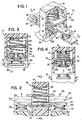
- a fault current tolerable contactor 10 is shown in perspective view.
- the contactor 10 has a movable contact carrier 12, which in turn has an upper enclosure 14, a pair of upwardly extending sides 15, and is movably mounted within a contactor housing 16.
- the movable contact carrier 12 is driven by a contactor operating mechanism (not shown) between a contact open position and a contact closed position in a well known manner.
- the contactor housing 16 has a pair of stationary contacts 18 mounted on conductors 19.
- a pair of movable contacts 20 are mounted to a contact bridge 22 in a window 23 in the contact carrier 12.
- the movable contacts 20 are additionally biased against the stationary contacts 18 when in the closed position, as shown in Fig. 1, by a biasing mechanism or spring 24 which is situated between the upper enclosure 14 of the movable contact carrier 12 and the contact bridge 22 supporting the movable contacts 20.
- a first magnetic component 26 is located adjacent contact bridge 22 between the bridge 22 and a lower surface of window 23 and is movable with the movable contacts 20 and the contact bridge 22 in an upward direction 28, as indicated in phantom in Fig. 2.
- a second magnetic component 30 is fixably mounted to the upwardly extending sides 15 between the movable contacts 20 and the upper enclosure 14 a given distance away from the first magnetic component 26 when the movable contacts 20 are in a closed position.
- the contactor 10 is shown in a closed position 32 and phantomed in an open position 34.
- the movable contacts 20 are positioned to conduct electrical current through the stationary contacts 18, the conductors 19, and the contact bridge 22.
- the open position 34 the current path is interrupted.
- Fig. 3 shows a detailed view of a portion of Fig. 2 with the contacts 18, 20 in the closed position.
- Each of the upwardly extending sides 15 in the movable contact carrier 12 has a slot 36, 38 on an inner wall 40, 42.
- the slots 36, 38 are parallel with one another to fixably retain the second magnetic component 30 therein.
- the second magnetic component 30 has a hollow center 34 to allow the biasing mechanism 24 to compressibly move within the second magnetic component 30 free of interference.
- the contactor 10 is shown with the stationary contacts 18 and the movable contacts 20 in the open position.
- the first magnetic component 26 is U-shaped such that when a fault current occurs through the contacts 18, 20, when closed, a high magnetic field is created between the first magnetic component 26 and the second magnetic component 30. This magnetic force pulls the first magnetic component 26 toward the stationary second magnetic component 30 thereby opening the contacts 18, 20, or assisting the opening during a blow-open condition, and maintaining the contacts open during the fault condition.
- the second magnetic component 30 could equivalently be U-shaped and the first magnetic component 26 could be U-shaped or planar. Other configurations could be adapted as long as the two magnetic components would be in physically close relationship with one another when the contacts are open.
- the magnetic components are comprised of a material with a high remnant flux density which allows a longer delay time before the contacts close after a zero current condition.
- the delay of contact closing can also be adjusted by adjusting the physical gap between the two magnetic components.
- the magnetic components can be comprised of steel plates which have been found to adequately protect the contacts from welding during fault conditions, while at the same time adding minimal cost to the contactor both in terms of component cost and modification cost.
- a method of preventing contact weld under high fault current conditions in an electromagnetic contactor includes providing a pair of contacts, wherein the contacts are movable between a closed position and an opened position with respect to the other contact, and providing an electrical current path through the contacts when the contacts are in the closed position.
- the invention includes pulling the contacts open during the presence of a fault current through the contacts due to the creation of a magnetic force between the movable contact and a stationary magnetic component of a magnitude sufficient to maintain the contacts open for the duration of the fault condition.
- the invention can also maintain contact separation for a period of time dependent on either the remnant flux associated with the material used for the magnetic components or the physical distance between the magnetic components, as previously described.
- the delay time until contact closure can be adjusted by adjusting the gap between the two magnetic components.
- the contacts are provided sufficient time to cool before closure which thereby prevents a welding of the contacts.
- An additional advantage is that the current through the contacts is limited during a fault condition due to a relatively quick opening of the contacts and because the contacts are maintained in an open position until the fault condition dissipates.
Landscapes
- Physics & Mathematics (AREA)
- Electromagnetism (AREA)
- Relay Circuits (AREA)
- Arc-Extinguishing Devices That Are Switches (AREA)
- Contacts (AREA)
- Breakers (AREA)
Priority Applications (1)
| Application Number | Priority Date | Filing Date | Title |
|---|---|---|---|
| EP06014585A EP1708223A3 (de) | 1998-07-21 | 1999-07-21 | Fehlerstromtolerantes Schütz |
Applications Claiming Priority (2)
| Application Number | Priority Date | Filing Date | Title |
|---|---|---|---|
| US120101 | 1980-02-28 | ||
| US09/120,101 US5959517A (en) | 1998-07-21 | 1998-07-21 | Fault current tolerable contactor |
Related Child Applications (1)
| Application Number | Title | Priority Date | Filing Date |
|---|---|---|---|
| EP06014585A Division EP1708223A3 (de) | 1998-07-21 | 1999-07-21 | Fehlerstromtolerantes Schütz |
Publications (3)
| Publication Number | Publication Date |
|---|---|
| EP0974997A2 true EP0974997A2 (de) | 2000-01-26 |
| EP0974997A3 EP0974997A3 (de) | 2000-08-16 |
| EP0974997B1 EP0974997B1 (de) | 2006-08-23 |
Family
ID=22388278
Family Applications (2)
| Application Number | Title | Priority Date | Filing Date |
|---|---|---|---|
| EP99114344A Expired - Lifetime EP0974997B1 (de) | 1998-07-21 | 1999-07-21 | Fehlerstromtoleranter Schütz |
| EP06014585A Withdrawn EP1708223A3 (de) | 1998-07-21 | 1999-07-21 | Fehlerstromtolerantes Schütz |
Family Applications After (1)
| Application Number | Title | Priority Date | Filing Date |
|---|---|---|---|
| EP06014585A Withdrawn EP1708223A3 (de) | 1998-07-21 | 1999-07-21 | Fehlerstromtolerantes Schütz |
Country Status (6)
| Country | Link |
|---|---|
| US (1) | US5959517A (de) |
| EP (2) | EP0974997B1 (de) |
| JP (1) | JP4193158B2 (de) |
| CN (1) | CN100345238C (de) |
| BR (1) | BR9903339A (de) |
| DE (1) | DE69932895T2 (de) |
Cited By (2)
| Publication number | Priority date | Publication date | Assignee | Title |
|---|---|---|---|---|
| EP1895562A1 (de) * | 2006-09-01 | 2008-03-05 | Siemens Aktiengesellschaft | Ein Strombegrenzer |
| EP2270829A1 (de) | 2009-07-01 | 2011-01-05 | Schneider Electric Industries SAS | Steuerung über eine Einrichtung zur magnetischen Kompensation einer Rückstosskraft und Schaltschutz mit einer solchen Vorrichtung |
Families Citing this family (46)
| Publication number | Priority date | Publication date | Assignee | Title |
|---|---|---|---|---|
| US6194984B1 (en) * | 1998-09-30 | 2001-02-27 | Rockwell Technologies, Llc | Movable contact assembly for an electrical contactor |
| US6380787B1 (en) * | 1999-08-31 | 2002-04-30 | Micron Technology, Inc. | Integrated circuit and method for minimizing clock skews |
| US6377143B1 (en) | 2001-03-16 | 2002-04-23 | Eaton Corporation | Weld-free contact system for electromagnetic contactors |
| US6943654B2 (en) * | 2003-02-28 | 2005-09-13 | Eaton Corporation | Method and apparatus to control modular asynchronous contactors |
| US6956728B2 (en) * | 2003-02-28 | 2005-10-18 | Eaton Corporation | Method and apparatus to control modular asynchronous contactors |
| US7196434B2 (en) * | 2003-03-21 | 2007-03-27 | Eaton Corporation | Modular contactor assembly having independently controllable contractors |
| US7057311B1 (en) | 2003-03-21 | 2006-06-06 | Eaton Corporation | Isolation contactor assembly having independently controllable contactors |
| US7224557B2 (en) * | 2003-06-28 | 2007-05-29 | Eaton Corporation | Method and system of controlling asynchronous contactors for a multi-phase electric load |
| US7317264B2 (en) * | 2003-11-25 | 2008-01-08 | Eaton Corporation | Method and apparatus to independently control contactors in a multiple contactor configuration |
| JP4393923B2 (ja) * | 2004-05-26 | 2010-01-06 | 三菱電機株式会社 | 電磁接触器 |
| US20060238285A1 (en) * | 2005-03-30 | 2006-10-26 | Dimig Steven J | Residual magnetic devices and methods |
| US20060219499A1 (en) * | 2005-03-30 | 2006-10-05 | Organek Gregory J | Residual magnetic devices and methods |
| US20060219496A1 (en) * | 2005-03-30 | 2006-10-05 | Dimig Steven J | Residual magnetic devices and methods |
| US8403124B2 (en) | 2005-03-30 | 2013-03-26 | Strattec Security Corporation | Residual magnetic devices and methods |
| US20060226941A1 (en) * | 2005-03-30 | 2006-10-12 | Dimig Steven J | Residual magnetic devices and methods |
| US20060226942A1 (en) * | 2005-03-30 | 2006-10-12 | Dimig Steven J | Residual magnetic devices and methods |
| US20060219498A1 (en) * | 2005-03-30 | 2006-10-05 | Organek Gregory J | Residual magnetic devices and methods |
| US20060219497A1 (en) * | 2005-03-30 | 2006-10-05 | Organek Gregory J | Residual magnetic devices and methods |
| US20060237959A1 (en) * | 2005-03-30 | 2006-10-26 | Dimig Steven J | Residual magnetic devices and methods |
| US20060219513A1 (en) * | 2005-03-30 | 2006-10-05 | Organek Gregory J | Residual magnetic devices and methods |
| US20060238284A1 (en) * | 2005-03-30 | 2006-10-26 | Dimig Steven J | Residual magnetic devices and methods |
| US7401483B2 (en) * | 2005-03-30 | 2008-07-22 | Strattec Security Corporation | Residual magnetic devices and methods for an ignition actuation blockage device |
| US7969705B2 (en) * | 2005-03-30 | 2011-06-28 | Strattec Security Corporation | Residual magnetic devices and methods |
| DE102007056165A1 (de) * | 2007-11-21 | 2009-05-28 | Epcos Ag | Überspannungsableiter mit thermischem Überlastschutz |
| US7990239B2 (en) * | 2009-05-08 | 2011-08-02 | M&Fc Holding, Llc | Electricity meter contact arrangement |
| CN101908441A (zh) * | 2010-07-02 | 2010-12-08 | 北海市深蓝科技发展有限责任公司 | 一种能减少抖动的继电器触头结构 |
| DE102012102431B4 (de) * | 2012-03-21 | 2019-11-07 | Te Connectivity Germany Gmbh | Leitungsschutzschalter |
| JP5845467B2 (ja) * | 2014-06-18 | 2016-01-20 | パナソニックIpマネジメント株式会社 | 接点装置 |
| KR101741586B1 (ko) * | 2014-10-31 | 2017-05-30 | 엘에스산전 주식회사 | 전자접촉기 크로스바 구조 |
| US10074497B2 (en) | 2014-11-06 | 2018-09-11 | Rockwell Automation Technologies, Inc. | Operator coil parameter based electromagnetic switching |
| US9806641B2 (en) | 2014-11-06 | 2017-10-31 | Rockwell Automation Technologies, Inc. | Detection of electric motor short circuits |
| US9748873B2 (en) | 2014-11-06 | 2017-08-29 | Rockwell Automation Technologies, Inc. | 5-pole based wye-delta motor starting system and method |
| US10361051B2 (en) | 2014-11-06 | 2019-07-23 | Rockwell Automation Technologies, Inc. | Single pole, single current path switching system and method |
| US9726726B2 (en) | 2014-11-06 | 2017-08-08 | Rockwell Automation Technologies, Inc. | Single-pole, single current path switching system and method |
| US9806642B2 (en) | 2014-11-06 | 2017-10-31 | Rockwell Automation Technologies, Inc. | Modular multiple single-pole electromagnetic switching system and method |
| US9722513B2 (en) | 2014-11-06 | 2017-08-01 | Rockwell Automation Technologies, Inc. | Torque-based stepwise motor starting |
| US10141143B2 (en) | 2014-11-06 | 2018-11-27 | Rockwell Automation Technologies, Inc. | Wear-balanced electromagnetic motor control switching |
| CN105070591A (zh) * | 2015-07-20 | 2015-11-18 | 昆山国力真空电器有限公司 | 密封型直流接触器 |
| US10026577B2 (en) * | 2015-09-04 | 2018-07-17 | Omron Corporation | Contact switching device |
| US10176953B2 (en) * | 2016-09-29 | 2019-01-08 | Schneider Electric USA, Inc. | Weld resistant contactor |
| CN107170648A (zh) * | 2017-07-11 | 2017-09-15 | 珠海格力电器股份有限公司 | 接触器及具有其的换热设备 |
| DE102017220503B3 (de) * | 2017-11-16 | 2019-01-17 | Te Connectivity Germany Gmbh | Doppelt unterbrechender Schalter |
| US10290435B1 (en) | 2018-03-14 | 2019-05-14 | Eaton Intelligent Power Limited | Magnetic circuit arrangement for an electrical switch |
| KR102652522B1 (ko) * | 2018-11-09 | 2024-03-29 | 샤먼 홍파 일렉트릭 파워 컨트롤즈 컴퍼니 리미티드 | 단락전류 방지용 직류 릴레이 |
| DE102021128179A1 (de) * | 2021-10-28 | 2023-05-04 | Te Connectivity Germany Gmbh | Schaltkontaktbaugruppe für ein elektrisches Schaltelement und elektrisches Schaltelement |
| CN115692050B (zh) * | 2022-09-07 | 2023-08-15 | 中国科学院电工研究所 | 一种脉冲大电流开关装置的开关机构 |
Family Cites Families (6)
| Publication number | Priority date | Publication date | Assignee | Title |
|---|---|---|---|---|
| NL266598A (de) * | 1960-07-13 | |||
| US3225160A (en) * | 1963-10-25 | 1965-12-21 | Gen Electric | Electric switch |
| DE6607399U (de) * | 1967-10-07 | 1971-02-25 | Kloeckner Moeller Elek Zitaets | Leistungsschalter |
| US3702980A (en) * | 1971-06-02 | 1972-11-14 | Yasuo Kasahara | Circuit breaker |
| FR2559308B1 (fr) * | 1984-02-03 | 1986-10-17 | Telemecanique Electrique | Contact equipe d'un compensateur magnetique avec seuil de liberation reglable et contacteur-disjoncteur utilisant un tel contact |
| FR2570869A1 (fr) * | 1984-09-25 | 1986-03-28 | Hager Electro | Perfectionnement aux ensembles de contact des interrupteurs a coupure |
-
1998
- 1998-07-21 US US09/120,101 patent/US5959517A/en not_active Expired - Lifetime
-
1999
- 1999-07-16 JP JP20302299A patent/JP4193158B2/ja not_active Expired - Fee Related
- 1999-07-21 DE DE69932895T patent/DE69932895T2/de not_active Expired - Fee Related
- 1999-07-21 EP EP99114344A patent/EP0974997B1/de not_active Expired - Lifetime
- 1999-07-21 EP EP06014585A patent/EP1708223A3/de not_active Withdrawn
- 1999-07-21 BR BR9903339-9A patent/BR9903339A/pt not_active IP Right Cessation
- 1999-07-21 CN CNB991106245A patent/CN100345238C/zh not_active Expired - Fee Related
Cited By (2)
| Publication number | Priority date | Publication date | Assignee | Title |
|---|---|---|---|---|
| EP1895562A1 (de) * | 2006-09-01 | 2008-03-05 | Siemens Aktiengesellschaft | Ein Strombegrenzer |
| EP2270829A1 (de) | 2009-07-01 | 2011-01-05 | Schneider Electric Industries SAS | Steuerung über eine Einrichtung zur magnetischen Kompensation einer Rückstosskraft und Schaltschutz mit einer solchen Vorrichtung |
Also Published As
| Publication number | Publication date |
|---|---|
| JP2000048701A (ja) | 2000-02-18 |
| EP1708223A3 (de) | 2008-04-02 |
| US5959517A (en) | 1999-09-28 |
| EP0974997B1 (de) | 2006-08-23 |
| JP4193158B2 (ja) | 2008-12-10 |
| EP1708223A2 (de) | 2006-10-04 |
| CN100345238C (zh) | 2007-10-24 |
| BR9903339A (pt) | 2000-03-14 |
| DE69932895D1 (de) | 2006-10-05 |
| EP0974997A3 (de) | 2000-08-16 |
| DE69932895T2 (de) | 2007-04-12 |
| CN1242586A (zh) | 2000-01-26 |
Similar Documents
| Publication | Publication Date | Title |
|---|---|---|
| US5959517A (en) | Fault current tolerable contactor | |
| EP1241699B1 (de) | Verschweissungsfreier Kontakt für elektromagnetische Schütze | |
| US8334740B2 (en) | Contactor assembly with arc steering system | |
| US5546061A (en) | Plunger type electromagnetic relay with arc extinguishing structure | |
| EP2037472B1 (de) | Schalter mit Lichtbogensteuerungssystem | |
| US8228655B2 (en) | Fault current limiter | |
| CN104520953A (zh) | 电接触设备、组件和操作方法 | |
| KR101309732B1 (ko) | 전기기계식 회로차단기 및 상기 전기기계식회로차단기에서의 전류차단 방법 | |
| US4013984A (en) | Current limiting circuit breaker | |
| EP0588588B1 (de) | Elektromagnetische Einrichtung | |
| KR20180120987A (ko) | 접점 개폐기 | |
| JP4393923B2 (ja) | 電磁接触器 | |
| JPH0136275Y2 (de) | ||
| HU215878B (hu) | Villamos megszakító villamos mágnes működtetőszervvel nagy teljesítményű áramkörökhöz | |
| JPH082906Y2 (ja) | 電磁継電器 | |
| US4642594A (en) | U-shaped solid magnetic core with at least one opening through the midsection thereof | |
| JP3072662B2 (ja) | 直流高速度遮断器 | |
| JPS62274515A (ja) | 開閉器 | |
| JPH0562581A (ja) | 電磁接触器の橋絡接触子 | |
| JPH02239524A (ja) | 開閉器 | |
| WO1989007327A1 (en) | Electric switching device | |
| JP2024171584A (ja) | リレー | |
| JPH06168655A (ja) | 操作用電磁石 | |
| JPS59103226A (ja) | 開閉器 | |
| JPS6122528A (ja) | 電気接点装置 |
Legal Events
| Date | Code | Title | Description |
|---|---|---|---|
| PUAI | Public reference made under article 153(3) epc to a published international application that has entered the european phase |
Free format text: ORIGINAL CODE: 0009012 |
|
| AK | Designated contracting states |
Kind code of ref document: A2 Designated state(s): DE FR GB |
|
| AX | Request for extension of the european patent |
Free format text: AL;LT;LV;MK;RO;SI |
|
| RIN1 | Information on inventor provided before grant (corrected) |
Inventor name: WIELOCK, CHRISTOPHER J. Inventor name: ZHOU, XIN |
|
| PUAL | Search report despatched |
Free format text: ORIGINAL CODE: 0009013 |
|
| AK | Designated contracting states |
Kind code of ref document: A3 Designated state(s): AT BE CH CY DE DK ES FI FR GB GR IE IT LI LU MC NL PT SE |
|
| AX | Request for extension of the european patent |
Free format text: AL;LT;LV;MK;RO;SI |
|
| RIC1 | Information provided on ipc code assigned before grant |
Free format text: 7H 01H 81/04 A, 7H 01H 71/10 B, 7H 01H 77/06 B |
|
| 17P | Request for examination filed |
Effective date: 20010115 |
|
| AKX | Designation fees paid |
Free format text: DE FR GB |
|
| 17Q | First examination report despatched |
Effective date: 20040315 |
|
| GRAP | Despatch of communication of intention to grant a patent |
Free format text: ORIGINAL CODE: EPIDOSNIGR1 |
|
| GRAS | Grant fee paid |
Free format text: ORIGINAL CODE: EPIDOSNIGR3 |
|
| GRAA | (expected) grant |
Free format text: ORIGINAL CODE: 0009210 |
|
| AK | Designated contracting states |
Kind code of ref document: B1 Designated state(s): DE FR GB |
|
| REG | Reference to a national code |
Ref country code: GB Ref legal event code: FG4D |
|
| REF | Corresponds to: |
Ref document number: 69932895 Country of ref document: DE Date of ref document: 20061005 Kind code of ref document: P |
|
| ET | Fr: translation filed | ||
| PLBE | No opposition filed within time limit |
Free format text: ORIGINAL CODE: 0009261 |
|
| STAA | Information on the status of an ep patent application or granted ep patent |
Free format text: STATUS: NO OPPOSITION FILED WITHIN TIME LIMIT |
|
| 26N | No opposition filed |
Effective date: 20070524 |
|
| PGFP | Annual fee paid to national office [announced via postgrant information from national office to epo] |
Ref country code: FR Payment date: 20090708 Year of fee payment: 11 |
|
| PGFP | Annual fee paid to national office [announced via postgrant information from national office to epo] |
Ref country code: GB Payment date: 20090612 Year of fee payment: 11 Ref country code: DE Payment date: 20090730 Year of fee payment: 11 |
|
| GBPC | Gb: european patent ceased through non-payment of renewal fee |
Effective date: 20100721 |
|
| REG | Reference to a national code |
Ref country code: FR Ref legal event code: ST Effective date: 20110331 |
|
| PG25 | Lapsed in a contracting state [announced via postgrant information from national office to epo] |
Ref country code: DE Free format text: LAPSE BECAUSE OF NON-PAYMENT OF DUE FEES Effective date: 20110201 |
|
| REG | Reference to a national code |
Ref country code: DE Ref legal event code: R119 Ref document number: 69932895 Country of ref document: DE Effective date: 20110201 |
|
| PG25 | Lapsed in a contracting state [announced via postgrant information from national office to epo] |
Ref country code: FR Free format text: LAPSE BECAUSE OF NON-PAYMENT OF DUE FEES Effective date: 20100802 |
|
| PG25 | Lapsed in a contracting state [announced via postgrant information from national office to epo] |
Ref country code: GB Free format text: LAPSE BECAUSE OF NON-PAYMENT OF DUE FEES Effective date: 20100721 |