EP0974747B1 - Système de commande pour moteur à combustion interne - Google Patents
Système de commande pour moteur à combustion interne Download PDFInfo
- Publication number
- EP0974747B1 EP0974747B1 EP99114363A EP99114363A EP0974747B1 EP 0974747 B1 EP0974747 B1 EP 0974747B1 EP 99114363 A EP99114363 A EP 99114363A EP 99114363 A EP99114363 A EP 99114363A EP 0974747 B1 EP0974747 B1 EP 0974747B1
- Authority
- EP
- European Patent Office
- Prior art keywords
- fuel
- engine
- air
- egr
- amount
- Prior art date
- Legal status (The legal status is an assumption and is not a legal conclusion. Google has not performed a legal analysis and makes no representation as to the accuracy of the status listed.)
- Expired - Lifetime
Links
Images


Classifications
-
- F—MECHANICAL ENGINEERING; LIGHTING; HEATING; WEAPONS; BLASTING
- F02—COMBUSTION ENGINES; HOT-GAS OR COMBUSTION-PRODUCT ENGINE PLANTS
- F02D—CONTROLLING COMBUSTION ENGINES
- F02D41/00—Electrical control of supply of combustible mixture or its constituents
- F02D41/0025—Controlling engines characterised by use of non-liquid fuels, pluralities of fuels, or non-fuel substances added to the combustible mixtures
- F02D41/0047—Controlling exhaust gas recirculation [EGR]
- F02D41/005—Controlling exhaust gas recirculation [EGR] according to engine operating conditions
- F02D41/0055—Special engine operating conditions, e.g. for regeneration of exhaust gas treatment apparatus
-
- F—MECHANICAL ENGINEERING; LIGHTING; HEATING; WEAPONS; BLASTING
- F01—MACHINES OR ENGINES IN GENERAL; ENGINE PLANTS IN GENERAL; STEAM ENGINES
- F01N—GAS-FLOW SILENCERS OR EXHAUST APPARATUS FOR MACHINES OR ENGINES IN GENERAL; GAS-FLOW SILENCERS OR EXHAUST APPARATUS FOR INTERNAL COMBUSTION ENGINES
- F01N13/00—Exhaust or silencing apparatus characterised by constructional features ; Exhaust or silencing apparatus, or parts thereof, having pertinent characteristics not provided for in, or of interest apart from, groups F01N1/00 - F01N5/00, F01N9/00, F01N11/00
- F01N13/009—Exhaust or silencing apparatus characterised by constructional features ; Exhaust or silencing apparatus, or parts thereof, having pertinent characteristics not provided for in, or of interest apart from, groups F01N1/00 - F01N5/00, F01N9/00, F01N11/00 having two or more separate purifying devices arranged in series
-
- F—MECHANICAL ENGINEERING; LIGHTING; HEATING; WEAPONS; BLASTING
- F01—MACHINES OR ENGINES IN GENERAL; ENGINE PLANTS IN GENERAL; STEAM ENGINES
- F01N—GAS-FLOW SILENCERS OR EXHAUST APPARATUS FOR MACHINES OR ENGINES IN GENERAL; GAS-FLOW SILENCERS OR EXHAUST APPARATUS FOR INTERNAL COMBUSTION ENGINES
- F01N13/00—Exhaust or silencing apparatus characterised by constructional features ; Exhaust or silencing apparatus, or parts thereof, having pertinent characteristics not provided for in, or of interest apart from, groups F01N1/00 - F01N5/00, F01N9/00, F01N11/00
- F01N13/011—Exhaust or silencing apparatus characterised by constructional features ; Exhaust or silencing apparatus, or parts thereof, having pertinent characteristics not provided for in, or of interest apart from, groups F01N1/00 - F01N5/00, F01N9/00, F01N11/00 having two or more purifying devices arranged in parallel
-
- F—MECHANICAL ENGINEERING; LIGHTING; HEATING; WEAPONS; BLASTING
- F01—MACHINES OR ENGINES IN GENERAL; ENGINE PLANTS IN GENERAL; STEAM ENGINES
- F01N—GAS-FLOW SILENCERS OR EXHAUST APPARATUS FOR MACHINES OR ENGINES IN GENERAL; GAS-FLOW SILENCERS OR EXHAUST APPARATUS FOR INTERNAL COMBUSTION ENGINES
- F01N3/00—Exhaust or silencing apparatus having means for purifying, rendering innocuous, or otherwise treating exhaust
- F01N3/08—Exhaust or silencing apparatus having means for purifying, rendering innocuous, or otherwise treating exhaust for rendering innocuous
- F01N3/0807—Exhaust or silencing apparatus having means for purifying, rendering innocuous, or otherwise treating exhaust for rendering innocuous by using absorbents or adsorbents
- F01N3/0828—Exhaust or silencing apparatus having means for purifying, rendering innocuous, or otherwise treating exhaust for rendering innocuous by using absorbents or adsorbents characterised by the absorbed or adsorbed substances
- F01N3/0842—Nitrogen oxides
-
- F—MECHANICAL ENGINEERING; LIGHTING; HEATING; WEAPONS; BLASTING
- F02—COMBUSTION ENGINES; HOT-GAS OR COMBUSTION-PRODUCT ENGINE PLANTS
- F02D—CONTROLLING COMBUSTION ENGINES
- F02D41/00—Electrical control of supply of combustible mixture or its constituents
- F02D41/02—Circuit arrangements for generating control signals
- F02D41/021—Introducing corrections for particular conditions exterior to the engine
- F02D41/0235—Introducing corrections for particular conditions exterior to the engine in relation with the state of the exhaust gas treating apparatus
- F02D41/027—Introducing corrections for particular conditions exterior to the engine in relation with the state of the exhaust gas treating apparatus to purge or regenerate the exhaust gas treating apparatus
- F02D41/0275—Introducing corrections for particular conditions exterior to the engine in relation with the state of the exhaust gas treating apparatus to purge or regenerate the exhaust gas treating apparatus the exhaust gas treating apparatus being a NOx trap or adsorbent
-
- F—MECHANICAL ENGINEERING; LIGHTING; HEATING; WEAPONS; BLASTING
- F02—COMBUSTION ENGINES; HOT-GAS OR COMBUSTION-PRODUCT ENGINE PLANTS
- F02D—CONTROLLING COMBUSTION ENGINES
- F02D41/00—Electrical control of supply of combustible mixture or its constituents
- F02D41/02—Circuit arrangements for generating control signals
- F02D41/14—Introducing closed-loop corrections
- F02D41/1438—Introducing closed-loop corrections using means for determining characteristics of the combustion gases; Sensors therefor
- F02D41/1439—Introducing closed-loop corrections using means for determining characteristics of the combustion gases; Sensors therefor characterised by the position of the sensor
- F02D41/1441—Plural sensors
- F02D41/1443—Plural sensors with one sensor per cylinder or group of cylinders
-
- F—MECHANICAL ENGINEERING; LIGHTING; HEATING; WEAPONS; BLASTING
- F02—COMBUSTION ENGINES; HOT-GAS OR COMBUSTION-PRODUCT ENGINE PLANTS
- F02D—CONTROLLING COMBUSTION ENGINES
- F02D41/00—Electrical control of supply of combustible mixture or its constituents
- F02D41/30—Controlling fuel injection
- F02D41/38—Controlling fuel injection of the high pressure type
- F02D41/40—Controlling fuel injection of the high pressure type with means for controlling injection timing or duration
- F02D41/402—Multiple injections
- F02D41/405—Multiple injections with post injections
-
- F—MECHANICAL ENGINEERING; LIGHTING; HEATING; WEAPONS; BLASTING
- F02—COMBUSTION ENGINES; HOT-GAS OR COMBUSTION-PRODUCT ENGINE PLANTS
- F02M—SUPPLYING COMBUSTION ENGINES IN GENERAL WITH COMBUSTIBLE MIXTURES OR CONSTITUENTS THEREOF
- F02M45/00—Fuel-injection apparatus characterised by having a cyclic delivery of specific time/pressure or time/quantity relationship
- F02M45/02—Fuel-injection apparatus characterised by having a cyclic delivery of specific time/pressure or time/quantity relationship with each cyclic delivery being separated into two or more parts
-
- F—MECHANICAL ENGINEERING; LIGHTING; HEATING; WEAPONS; BLASTING
- F01—MACHINES OR ENGINES IN GENERAL; ENGINE PLANTS IN GENERAL; STEAM ENGINES
- F01N—GAS-FLOW SILENCERS OR EXHAUST APPARATUS FOR MACHINES OR ENGINES IN GENERAL; GAS-FLOW SILENCERS OR EXHAUST APPARATUS FOR INTERNAL COMBUSTION ENGINES
- F01N2610/00—Adding substances to exhaust gases
- F01N2610/03—Adding substances to exhaust gases the substance being hydrocarbons, e.g. engine fuel
-
- F—MECHANICAL ENGINEERING; LIGHTING; HEATING; WEAPONS; BLASTING
- F02—COMBUSTION ENGINES; HOT-GAS OR COMBUSTION-PRODUCT ENGINE PLANTS
- F02D—CONTROLLING COMBUSTION ENGINES
- F02D41/00—Electrical control of supply of combustible mixture or its constituents
- F02D41/30—Controlling fuel injection
- F02D41/38—Controlling fuel injection of the high pressure type
- F02D2041/389—Controlling fuel injection of the high pressure type for injecting directly into the cylinder
-
- F—MECHANICAL ENGINEERING; LIGHTING; HEATING; WEAPONS; BLASTING
- F02—COMBUSTION ENGINES; HOT-GAS OR COMBUSTION-PRODUCT ENGINE PLANTS
- F02D—CONTROLLING COMBUSTION ENGINES
- F02D41/00—Electrical control of supply of combustible mixture or its constituents
- F02D41/0025—Controlling engines characterised by use of non-liquid fuels, pluralities of fuels, or non-fuel substances added to the combustible mixtures
- F02D41/0047—Controlling exhaust gas recirculation [EGR]
- F02D41/006—Controlling exhaust gas recirculation [EGR] using internal EGR
-
- F—MECHANICAL ENGINEERING; LIGHTING; HEATING; WEAPONS; BLASTING
- F02—COMBUSTION ENGINES; HOT-GAS OR COMBUSTION-PRODUCT ENGINE PLANTS
- F02D—CONTROLLING COMBUSTION ENGINES
- F02D41/00—Electrical control of supply of combustible mixture or its constituents
- F02D41/0025—Controlling engines characterised by use of non-liquid fuels, pluralities of fuels, or non-fuel substances added to the combustible mixtures
- F02D41/0047—Controlling exhaust gas recirculation [EGR]
- F02D41/0065—Specific aspects of external EGR control
-
- F—MECHANICAL ENGINEERING; LIGHTING; HEATING; WEAPONS; BLASTING
- F02—COMBUSTION ENGINES; HOT-GAS OR COMBUSTION-PRODUCT ENGINE PLANTS
- F02D—CONTROLLING COMBUSTION ENGINES
- F02D41/00—Electrical control of supply of combustible mixture or its constituents
- F02D41/02—Circuit arrangements for generating control signals
- F02D41/14—Introducing closed-loop corrections
- F02D41/1438—Introducing closed-loop corrections using means for determining characteristics of the combustion gases; Sensors therefor
- F02D41/1444—Introducing closed-loop corrections using means for determining characteristics of the combustion gases; Sensors therefor characterised by the characteristics of the combustion gases
- F02D41/1454—Introducing closed-loop corrections using means for determining characteristics of the combustion gases; Sensors therefor characterised by the characteristics of the combustion gases the characteristics being an oxygen content or concentration or the air-fuel ratio
- F02D41/1456—Introducing closed-loop corrections using means for determining characteristics of the combustion gases; Sensors therefor characterised by the characteristics of the combustion gases the characteristics being an oxygen content or concentration or the air-fuel ratio with sensor output signal being linear or quasi-linear with the concentration of oxygen
-
- F—MECHANICAL ENGINEERING; LIGHTING; HEATING; WEAPONS; BLASTING
- F02—COMBUSTION ENGINES; HOT-GAS OR COMBUSTION-PRODUCT ENGINE PLANTS
- F02D—CONTROLLING COMBUSTION ENGINES
- F02D41/00—Electrical control of supply of combustible mixture or its constituents
- F02D41/30—Controlling fuel injection
- F02D41/3011—Controlling fuel injection according to or using specific or several modes of combustion
- F02D41/3017—Controlling fuel injection according to or using specific or several modes of combustion characterised by the mode(s) being used
- F02D41/3023—Controlling fuel injection according to or using specific or several modes of combustion characterised by the mode(s) being used a mode being the stratified charge spark-ignited mode
- F02D41/3029—Controlling fuel injection according to or using specific or several modes of combustion characterised by the mode(s) being used a mode being the stratified charge spark-ignited mode further comprising a homogeneous charge spark-ignited mode
-
- Y—GENERAL TAGGING OF NEW TECHNOLOGICAL DEVELOPMENTS; GENERAL TAGGING OF CROSS-SECTIONAL TECHNOLOGIES SPANNING OVER SEVERAL SECTIONS OF THE IPC; TECHNICAL SUBJECTS COVERED BY FORMER USPC CROSS-REFERENCE ART COLLECTIONS [XRACs] AND DIGESTS
- Y02—TECHNOLOGIES OR APPLICATIONS FOR MITIGATION OR ADAPTATION AGAINST CLIMATE CHANGE
- Y02T—CLIMATE CHANGE MITIGATION TECHNOLOGIES RELATED TO TRANSPORTATION
- Y02T10/00—Road transport of goods or passengers
- Y02T10/10—Internal combustion engine [ICE] based vehicles
- Y02T10/40—Engine management systems
Definitions
- the present invention relates to a control system for an internal combustion engine. More specifically; the invention relates to a control system for an internal combustion engine, for supplying ineffective fuel which does not burn in the combustion chamber.
- a NO x occluding and reducing catalyst is disposed in the exhaust passage of the engine which operates at a lean air-fuel ratio, the NO x occluding and reducing catalyst absorbing NO x in the exhaust gas when the air-fuel ratio of the exhaust gas flowing in is lean, and releasing and purifying by reduction the absorbed NO x when the air-fuel ratio in the exhaust gas becomes rich.
- the air-fuel ratio of the exhaust gas flowing into the NO x occluding and reducing catalyst must be set to be rich at regular intervals and the NO x must be released from the NO x occluding and reducing catalyst, so that the NO x occluding and reducing catalyst will not be saturated with NO x when the engine is operated at a lean air-fuel ratio.
- a change in the engine operating air-fuel ratio from the lean side to the rich side increases the engine output torque; i.e., a change in the air-fuel ratio changes the torque.
- the ineffective fuel can be supplied into the cylinders by secondary fuel injection in the expansion stroke or in the exhaust stroke of the cylinders.
- the ineffective fuel can be supplied into the exhaust ports by the exhaust port fuel injection.
- the fuel injected into the cylinder during the expansion stroke or the exhaust stroke or the fuel injected into the exhaust port of the cylinder is vaporized without being burned and is discharged together with the exhaust gas. That is, the ineffective fuel that is supplied does not contribute to the combustion in the engine, but the amount of the unburned HC component in the exhaust gas from the engine increases by an amount.of the ineffective fuel that is supplied to establish a rich air-fuel ratio.
- the ineffective fuel By supplying the ineffective fuel to the engine, therefore, it is possible to change the air-fuel ratio only in the exhaust gas from the engine without affecting the engine operating air-fuel ratio.
- a device for supplying the ineffective fuel of this type has been disclosed in, for example, Japanese Unexamined Patent Publication (Kokai) No. 6-212961.
- a NO x occluding and reducing catalyst is disposed in the exhaust passage of a diesel engine to absorb the NO x in the exhaust gas when the air-fuel ratio of the exhaust gas flowing in is lean and to release the NO x when the oxygen concentration has decreased in the exhaust gas that is flowing in.
- the main fuel is injected into the cylinder near the compressive top dead center of the cylinder of the engine and, when the NO x is to be released from the NO x occluding and reducing catalyst, the secondary fuel is injected during the expansion stroke or the exhaust stroke of the engine in addition to injecting the main fuel.
- the fuel injected into the cylinder during the expansion or exhaust stroke does not contribute to the combustion in the cylinder, i.e., does not burn in the cylinder and is exposed to the burned gas of a high temperature in the cylinder. Therefore, hydrocarbons having large molecular weights in the fuel are decomposed into hydrocarbons having small molecular weights.
- the fuel supplied by the secondary fuel injection does not contribute to the combustion but is simply discharged from cylinders together with the exhaust gas. By supplying the ineffective fuel to the engine, therefore, it is made possible to inject the fuel in a relatively large amount for establishing a rich air-fuel ratio in the exhaust gas without increasing the pressure of an explosion in the cylinder even in a diesel engine.
- the exhaust gas having a rich air-fuel ratio containing a large amount of hydrocarbons of low molecular weights which are highly active, flows into the NO x occluding and reducing catalyst in the exhaust passage.
- the secondary fuel is injected, therefore, the NO x that has been absorbed is released from the NO x occluding and reducing catalyst and is purified by reduction with hydrocarbons in the exhaust gas.
- EGR exhaust gas recirculation
- the exhaust gas recirculation system includes an external EGR system in which an exhaust passage of the engine is connected to an intake passage of the engine through an EGR passage, and the amount of the exhaust gas to be recirculated is adjusted by a flow rate adjusting valve (EGR valve) provided in the EGR passage, and an internal EGR system by which the amount of blow back of the burned gas in the combustion chamber caused by the overlapping of valve is adjusted by changing the open-close timings of the intake valve and the exhaust valve of the engine.
- EGR valve flow rate adjusting valve
- the exhaust gas from the engine contains unburned fuel in relatively large amounts.
- the exhaust gas is directly recirculated by the EGR device into the combustion chamber of the engine, part of the ineffective fuel that should not burn in the combustion chamber is recirculated into the combustion chamber and burns therein.
- the ineffective fuel is supplied while the EGR is being performed, therefore, the fuel is supplied in an excess amount into the engine and the combustion air-fuel ratio becomes excessively rich, whereby the combustion in the combustion chamber becomes unstable or the output torque of the engine increases due to the combustion of excess fuel.
- EP 0 752 521 A1 discloses an in-cylinder injection type internal combustion engine that is, from time to time, supplied with additional fuel during the cylinder expansion stroke which is exhausted from the combustion chamber in the form of unburned or ineffective fuel.
- An EGR gas passage recirculates exhaust gas from the engine into the combustion chamber of the engine. In order to prevent the air-fuel mixture around the spark plug from becoming overly rich with the result of misfires, the amount of EGR gas is reduced by closing an EGR valve.
- the object of the present invention is to provide a control system for an internal combustion engine capable of not only preventing the combustion from becoming unstable, but also preventing a change in the output torque caused by the recirculation of the fuel in the combustion chamber and reducing fuel consumption.
- a control system for an internal combustion engine comprising:
- the supply of the ineffective fuel is limited by the ineffective fuel limiting means when the EGR is executed. Therefore, the ineffective fuel is recirculated into the combustion chamber of the engine together with the recirculated exhaust gas.
- "limit the supply of the ineffective fuel” includes both the case where the ineffective fuel is supplied in a decreased amount and the case where the supply of the ineffective fuel is completely interrupted.
- Fig. 1 is a view schematically illustrating the constitution of an internal combustion engine for an automobile to which the invention is not applied.
- reference numeral 1 denotes an internal combustion engine for an automobile.
- the engine 1 is a four-cylinder gasoline engine having four cylinders #1 to #4 which are equipped with fuel injection valves 111 to 114 for directly injecting fuel into the cylinders.
- the internal combustion engine 1 of this example is a lean-burn engine that can be operated at an air-fuel ratio higher (more lean) than the stoichiometric air-fuel ratio.
- the cylinders #1 to #4 are grouped into two groups of cylinders each group including two cylinders so that the ignition timings will not take place consecutively (in the example of Fig. 1, for example, the order of igniting the cylinders is 1-3-4-2, the cylinders #1 and #4 constituting one group of cylinders, and the cylinders #2 and #3 constituting another group of cylinders).
- the exhaust port of each cylinder is connected to an exhaust manifold of each group of cylinders, and is connected to an exhaust passage of each group of cylinders.
- reference numeral 21a denotes an exhaust manifold for connecting exhaust ports of the group of the cylinders #1 and #4 to an independent exhaust passage 2a
- reference numeral 21b denotes an exhaust manifold for connecting exhaust ports of the group of the cylinders #2 and #4 to an independent exhaust passage 2b.
- start catalysts hereinafter referred to as "SCs"
- SCs start catalysts 5a and 5b comprising a three-way catalyst are arranged in the independent exhaust passages 2a and 2b.
- the independent exhaust passages 2a and 2b meet together in a common exhaust passage 2 on the downstream side of the SCs.
- FIG. 1 An NO x occluding and reducing catalyst 7 that will be described later is arranged in the common exhaust passage 2.
- reference numerals 29a and 29b denote air-fuel ratio sensors arranged on the upstream side of the start catalysts 5a and 5b of the independent exhaust passages 2a and 2b
- reference numeral 31 denotes an air-fuel ratio sensor arranged at an outlet of the NO x occluding and reducing catalyst 7 in the exhaust passage 2.
- the air-fuel ratio sensors 29a, 29b and 31 are so-called linear air-fuel ratio sensors that produce voltage signals corresponding to the air-fuel ratio of the exhaust gas over a wide range of air-fuel ratios.
- a throttle valve 15 is installed in the intake passage 10.
- the throttle valve 15 in this example is a so-called electronically controlled throttle valve which is driven by an actuator 15a of a suitable form such as a step motor to define a degree of opening based on a control signal from an ECU 30 that will be described later.
- reference numeral 15b denotes a throttle valve opening-degree sensor (throttle sensor) for detecting the opening degree of the throttle valve 15.
- the direct cylinder fuel injection valves 111 to 114 are separately connected to a reservoir (common rail) 110 to inject the fuel of a high pressure in the common rail 110 into the cylinders.
- reference numeral 130 denotes a fuel pump comprising a high-pressure pump such as plunger pump. The fuel pump 130 supplies a high pressure fuel to the common rail 110 at a timing just after the fuel is injected by the fuel injection valves (111 to 114).
- reference numeral 200 denotes a variable valve timing device for varying the valve timings of the engine 1.
- the variable valve timing device 200 may be any known type provided it is capable of changing the valve timings of the engine based on an instruction signal from an ECU 30 that will be described later, and may be either one which changes the open-close timings only of the intake valves and/or the exhaust valves, or one which changes the valve lift in addition to the open-close timings.
- the valve timings may be changed either continuously or stepwisely.
- reference numeral 30 denotes the ECU (engine control, unit) for controlling the engine 1.
- the ECU 30 comprises a widely known microcomputer having RAM, ROM and CPU that are connected together through a bidirectional bus, and executes basic control operations such as controlling the main fuel injection and the ignition timings.
- the ECU 30 further works to change the combustion in the cylinder into a rich air-fuel ratio during a regenerating operation of the NO x occluding and reducing catalyst that will be described later, and controls the secondary fuel injection by injecting the secondary fuel during the expansion or exhaust stroke of each cylinder to change the air-fuel ratio of the exhaust gas flowing into the NO x occluding and reducing catalyst to a rich air-fuel ratio within a short period of time.
- the input port of the ECU 30 receives signals from the air-fuel ratio sensors 29a and 29b representing the exhaust gas air-fuel ratios at the inlet of the start catalysts 5a and 5b, a signal from the air-fuel ratio sensor 31 representing an exhaust gas air-fuel ratio at the outlet of the NO x occluding and reducing catalyst 7, a signal corresponding to the intake air pressure of the engine from an intake-air-pressure sensor 37 provided in the surge tank 10a, and a signal from the accelerator opening-degree sensor 33 representing the amount of the accelerator pedal depressed by the driver (accelerator opening degree), and a pulse signal from a rotational speed sensor 35 disposed near the crankshaft (not shown) of the engine after every predetermined rotational angle of the engine crankshaft.
- the ECU 30 calculates the rotational angle of the crankshaft from the pulse signal, and calculates the rotational speed of the engine from the frequency of the pulse signals. Further, the input port of the ECU 30 receives a signal from a fuel pressure sensor 120 arranged in the common rail 110 representing the fuel pressure in the common rail 110, and a signal from the throttle valve opening-degree sensor 15b representing the opening degree of the throttle valve 15.
- the output port of the ECU 30 is connected to fuel injection valves 111 to 114 of the cylinders through a fuel injection circuit (not shown), and is further connected to the actuator 15b of the throttle valve 15 through a drive circuit (not shown) to control the opening degree of the throttle valve 15.
- the ECU 30 controls by feedback the rate of the fuel supplied by the fuel pump 130 based on the signal representing the fuel pressure in the common rail 110 input from the fuel pressure sensor 120, so that the fuel pressure in the common rail is adjusted to a target value.
- the fuel is supplied from the fuel pump 130 to the common rail 110 at a timing just after the fuel is injected by the fuel injection valves 111 to 114.
- the output port of the ECU 30 is connected to the variable valve timing device 200 through a drive circuit (not shown) to control the valve timings of the engine 1 based on the engine load conditions (degree of accelerator opening, engine rotational speed).
- the main fuel injection of the engine 1 i.e., the injection of fuel for combustion in the cylinder, is controlled in the following five modes based upon the loads exerted on the engine:
- the lean air-fuel ratio stratified charge combustion 1 ⁇ is carried out in the light-load operating region of the engine 1.
- the fuel is injected into the cylinders only one time in the latter half of the compression stroke in each cylinder, and the injected fuel forms a charge of a combustible mixture near the spark plug in the cylinder.
- the amount of fuel injected is very small, and the air-fuel ratio in the cylinder as a whole becomes from about 25 to about 30.
- the fuel is injected in advance in the former half of the suction stroke in an amount to compensate for the shortage of the fuel injected in the latter half of the compression stroke, thereby to supply the fuel in a target amount into the cylinder.
- the fuel injected into the cylinder in the former half of the suction stroke forms a very lean and uniform mixture before being ignited.
- the fuel is further injected into this very lean and uniform mixture in order to form the charge of an ignitable and combustible mixture near the spark plug.
- this combustible mixture charge starts burning, and the flame propagates to the surrounding lean mixture charge, so that the combustion takes place stably.
- the amount of fuel injected in the suction stroke and in the compression stroke is larger than that of the mode 1 ⁇ , but the air-fuel ratio as a whole is still lean (e.g., air-fuel ratio of about 20 to about 30).
- the engine 1 When the load on the engine further increases, the engine 1 is operated in the lean air-fuel ratio uniform mixture combustion 3 ⁇ . In this state, the fuel is injected only one time in the former half of the suction stroke, and the amount of the injected fuel becomes larger than that of the mode 2 ⁇ .
- the uniform air-fuel mixture formed in the cylinder in this state has a lean air-fuel ratio (e.g., air-fuel ratio of from about 15 to about 25) relatively close to the stoichiometric air-fuel ratio.
- the amount of fuel becomes larger than that of the mode 3 ⁇ , and the engine is operated in the stoichiometric air-fuel ratio uniform mixture operation 4 ⁇ .
- a uniform mixture of the stoichiometric air-fuel ratio is formed in the cylinder, and the engine output increases.
- the amount of fuel injection is further increased in excess of that of the mode 4 ⁇ , and the engine is operated in the rich air-fuel ratio uniform mixture operation 5 ⁇ .
- the uniform mixture formed in the cylinder becomes a rich air-fuel ratio (e.g., air-fuel ratio of from about 12 to about 14).
- optimum operation modes 1 ⁇ to 5 ⁇ have been empirically set based upon the degree of accelerator opening (amount of the accelerator pedal depressed by the driver) and the rotational speed of the engine, and a map using the degree of accelerator opening and the engine rotational speed is stored in the ROM of the ECU 30.
- the ECU 30 determines which one of the above-mentioned operation modes 1 ⁇ to 5 ⁇ be selected based on the degree of accelerator opening detected by the accelerator opening-degree sensor 37 and the rotational speed of the engine, and determines the amount of fuel injection, timing for fuel injection, the number of times of injection and the degree of throttle valve opening based on each of the modes.
- the ECU 30 determines the amount of fuel injection from the degree of accelerator opening and the rotational speed of the engine based on a map that has been prepared in advance for each of the modes 1 ⁇ to 3 ⁇ .
- the ECU 30 sets the amount of fuel injection based on the intake air pressure detected by the intake air pressure sensor 37 and the rotational speed of the engine by using a map that has been prepared in advance for each of the modes 4 ⁇ and 5 ⁇ .
- the ECU 30 controls the air-fuel ratio by correcting the amount of fuel injection calculated above by feedback based on the outputs of the air-fuel ratio sensors 29a and 29b, so that the air-fuel ratio of the exhaust gas emitted by the engine becomes the stoichiometric air-fuel ratio.
- the start catalysts (SCs) 5a and 5b are constituted as a three-way catalyst by using a honeycomb-shaped substrate of cordierite or the like, forming a thin coating of alumina on the surface of the substrate, and carrying a novel metal catalyst component such as platinum Pt, palladium Pd or rhodium Rh on the alumina layer.
- the three-way catalyst highly efficiently removes the three components, i.e., HC, CO and NO x near the stoichiometric air-fuel ratio.
- the three-way catalyst exhibits a decreased ability for reducing NO x when the air-fuel ratio of the exhaust gas flowing in becomes higher than the stoichiometric air ratio. When the engine 1 is operating at a lean air-fuel ratio, therefore, the three-way catalyst is not capable of removing NO x in the exhaust gas to a Sufficient degree.
- the start catalysts (SCs) 5a and 5b chiefly work to purify the exhaust gas of when the engine 1 is operating at a rich air-fuel ratio immediately after the cold starting and to purity the exhaust gas of when the engine 1 is operating at the stoichiometric air-fuel ratio under normal operating condition. Therefore, the start catalysts (SCs) 5a and 5b are disposed in the exhaust passages 2a and 2b at positions close to the engine 1 and have a relatively small capacity to decrease their heat capacity, so that they can be heated to their activated temperature within a short period of time after the start of the engine to start their catalytic activity.
- the NO x occluding and reducing catalyst 7 uses alumina as a substrate to carry at least one component selected from the alkali metals such as potassium K, sodium Na, lithium Li and cesium Cs, alkaline earth elements such as barium Ba and calcium Ca, and rare earth elements such as lanthanum La, cerium Ce and yttrium Y, as well as a noble metal such as platinum Pt.
- alkali metals such as potassium K, sodium Na, lithium Li and cesium Cs
- alkaline earth elements such as barium Ba and calcium Ca
- rare earth elements such as lanthanum La, cerium Ce and yttrium Y, as well as a noble metal such as platinum Pt.
- the NO x occluding and reducing catalyst exhibits the action of absorbing and releasing NO x , i.e., absorbs NO x (nitrogen oxides) in the exhaust gas in the form of nitric acid ions NO 3 - when the air-fuel ratio of the exhaust gas flowing in is lean, and releases the absorbed NO x when the air-fuel ratio of the exhaust gas flowing in becomes smaller than the stoichiometric air-fuel ratio (rich air-fuel ratio).
- NO 2 forms in a decreased amount on platinum Pt, and the reaction proceeds in the reverse direction permitting nitric acid ions NO 3 - in the absorbing agent to be released in the form of NO 2 from the absorbing agent.
- the reducing components such as CO and the like and the components such as HC, CO 2 and the like in the exhaust gas work to reduce NO 2 on platinum Pt.
- the engine 1 is normally operated at a lean air-fuel ratio in most of the load regions except the high-load operation, and the NO x occluding and reducing catalyst absorbs NO x in the exhaust gas that flows in.
- the NO x occluding and reducing catalyst 7 releases and purifies the absorbed NO x by reduction.
- a rich-spike operation is carried out to change the air-fuel ratio of the engine from a lean air-fuel ratio to a rich air-fuel ratio for a short period of time in order to release NO x from the NO x occluding and reducing catalyst and to purify NO x by reduction (to regenerate the NO x occluding and reducing catalyst).
- the secondary fuel is injected during the expansion or the exhaust stroke after the main fuel injection in order to quickly change the air-fuel ratio of the exhaust gas to a considerably rich air-fuel ratio, so that the unpurified NO x will not be released from the NO x occluding and reducing catalyst.
- the fuel is injected in the expansion or the exhaust stroke and remains unburned and comes in contact with the burned gas of a high temperature, and is vaporized to form hydrocarbons of low molecular weights.
- the fuel supplied by the secondary fuel injection does not contribute to the combustion in the cylinder.
- the output torque of the engine does not increase.
- the secondary fuel is injected when the NO x is to be released from the NO x occluding and reducing catalyst, therefore, the air-fuel ratio of the exhaust gas can be quickly changed down to a low value without causing a change in the output torque of the engine. It is therefore possible to supply the exhaust gas having a high rich degree to the NO x occluding and reducing catalyst without passing through a region of intermediate air-fuel ratios. This prevents the release of unpurified NO x from the NO x occluding and reducing catalyst in the early period of the NO x releasing action.
- the NO x may be released from the NO x occluding and reducing catalyst relying on the secondary fuel injection only or by effecting the secondary fuel injection at the initial period only of the rich-spike operation at the time of conducting the normal rich-spike operation by increasing the amount of main fuel injection thereby to quickly change the air-fuel ratio of the exhaust gas to a rich air-fuel ratio.
- the ECU 30 calculates the required amount of fuel based on the engine load conditions (degree of accelerator opening, rotational speed) and supplies the fuel into the cylinder by the main fuel injection.
- the fuel due to the secondary fuel injection remains in the cylinders, therefore, this remaining fuel burns in the cylinders in addition to the fuel supplied by the main fuel injection of the next cycle; i.e., the output torque of the engine increases due to the combustion of the fuel of an amount larger than the required amount, and the torque changes.
- Fig. 2 schematically illustrates the constitution of this example and is similar to Fig. 1.
- reference numerals same as those of Fig. 1 denote the same elements.
- Fig. 2 is different from the example of Fig. 1 with respect to the provision of an exhaust gas recirculation device for recirculating part of the exhaust gas of the engine into the engine intake air system.
- the engine 1 in this example is equipped with the common rail 110, throttle valve 15, etc. like in the example of Fig. 1.
- the upstream side of the SC 5b of the exhaust passage 2b of the cylinders #2 and #3 is connected to the surge tank 10a of the engine intake passage 10 through an EGR passage 43.
- an EGR valve 41 comprising a flow rate control valve is provided in the EGR passage 43 to control the flow rate of the exhaust gas recirculating from the exhaust passage 2b to the intake passage 10 through the EGR passage.
- the EGR valve 41 is equipped with an actuator 41a of a suitable form such as step motor, negative-pressure actuator, etc. that operates in response to a control signal from the ECU 30, and determines its opening degree based on the control signal from the ECU 30.
- the ECU 30 changes the fuel injection mode of the direct cylinder injection valves 111 to 114 in the same manner as in the embodiment of Fig. 1, and operates the engine in any one of the below-mentioned five modes based on the engine operating conditions.
- the ECU 30 controls the EGR valve 41 to recirculate part of the exhaust gas into the intake passage 10 from the exhaust passage 2b based on the engine operating conditions. In other words, this example executes the external EGR.
- the output port of the ECU 30 is connected to the actuator 41a of the EGR valve through a drive circuit (not shown) to control the opening degree of the EGR valve 41.
- the ineffective fuel that does not burn in the cylinder is supplied to the engine so that the exhaust gas from the engine becomes a rich air-fuel ratio, thereby to release NO x from the NO x occluding and reducing catalyst and to purify the NO x by reduction (to regenerate the NO x occluding and reducing catalyst).
- the ECU 30 increases or decreases the value of an NO x counter in order to estimate the amount of NO x absorbed and held by the NO x occluding and reducing catalyst 7.
- the amount of NO x absorbed by the NO x occluding and reducing catalyst 7 per a unit time varies in proportion to the amount of NO x in the exhaust gas flowing into the NO x occluding and reducing catalyst per a unit time, i.e., varies in proportion to the amount of NO x generated by the engine 1 per a unit time.
- the amount of NO x generated by the engine per a unit time is determined by the amount of fuel fed to the engine, air-fuel ratio, flow rate of the exhaust gas, etc.
- the engine operating conditions degree of accelerator opening, engine rotational speed, amount of the air taken in, intake air pressure, air-fuel ratio, amount of feeding fuel, etc.
- the amount of NO x generated by the engine per a unit time is changed to measure the amount of NO x generated by the engine per a unit time, and the amount of NO x absorbed by the NO x occluding and reducing catalyst 7 per a unit time is stored in the ROM of ECU 30 in the form of a numerical value table using, for example, load on the engine (amount of fuel injection) and the engine rotational speed as parameters.
- the ECU 30 calculates the amount of NO x absorbed by the NO x occluding and reducing catalyst per a unit time after every predetermined period of time (after every unit time) by using the load on the engine (amount of fuel injection) and the engine rotational speed, and increases the value of the NO x counter by the amount of NO x absorbed. Therefore, the value of the NO x counter always indicates the amount of NO x absorbed by the NO x occluding and reducing catalyst 7.
- the ECU 30 supplies to the engine the fuel that does not burn in the combustion chamber to change the air-fuel ratio of the exhaust gas of the engine over to a rich air-fuel ratio. Therefore, the exhaust gas having a rich air-fuel ratio flows into the NO x occluding and reducing catalyst irrespective of the engine operating air-fuel ratio. Therefore, the absorbed NO x is released from the NO x occluding and reducing catalyst and is purified by reduction.
- the time for maintaining the exhaust gas air-fuel ratio rich by supplying the ineffective fuel is experimentally determined based upon the kind and volume of the NO x occluding and reducing catalyst.
- the value of the NO x counter is reset to 0 after the NO x is released from the NO x occluding and reducing catalyst and is purified by reduction upon supplying the ineffective fuel.
- the NO x occluding and reducing catalyst 7 is properly regenerated and is not saturated with the absorbed NO x .
- the ineffective fuel is supplied by the two methods, i.e., a method which injects the secondary fuel from the direct cylinder fuel injection valve into the cylinder in the expansion stroke or the exhaust stroke of the cylinder, and a method which injects the fuel into the exhaust port.
- the ineffective fuel is supplied to the engine by the secondary fuel injection.
- the present invention can be similarly applied even to the engine equipped with exhaust port fuel injection valves and in which the ineffective fuel is applied by the exhaust port fuel injection.
- the exhaust gas of the engine contains relatively large amounts of unburned fuel supplied as the ineffective fuel.
- the exhaust gas containing relatively large amounts of unburned fuel is recirculated into the intake passage 10 through the EGR passage 43, and the unburned fuel is supplied into the combustion chamber in the cylinder and is burned in the combustion chamber.
- the amount of fuel injection into the engine (hereinafter referred to as the amount of main fuel injection to make a distinction over the ineffective fuel) is controlled to an optimum value by the ECU 30 based on the engine operating conditions.
- the EGR is limited to solve the above-mentioned problem. That is, the EGR is limited (e.g., interrupted), whereby no exhaust gas containing the unburned fuel recirculates into the combustion chamber of the engine. Therefore, the combustion air-fuel ratio in the combustion chamber varies in proportion to the amount of main fuel injection, and the air-fuel ratio is prevented from becoming more rich than an optimum value.
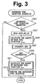
- Fig. 3 is a flow chart illustrating the operation of the secondary fuel injection according to an example outside the terms of the claims. This operation is conducted by a routine executed by the ECU 30 at every predetermined interval (e.g., at every predetermined crankshaft rotation angle).
- the ECU 30 requests the secondary fuel injection for a predetermined period of time only when the value of the NO x counter CNOX of the NO x occluding and reducing catalyst 7 becomes larger than a predetermined value.
- the degree of accelerator opening ACCP, the engine rotational speed NE and the engine intake air pressure PM are read at a step 1003 and where the present operation mode (1 ⁇ to 5 ⁇ ) is judged from ACCP and NE. Further, the present main fuel injection amount qINJ of the engine is calculated from the numerical value table prepared for each of the operation modes based on ACCP and NE (modes 1 ⁇ to 3 ⁇ ) or based on PM and NE (modes 4 ⁇ and 5 ⁇ ).
- the EGR is interrupted.
- the EGR is interrupted by fully closing the EGR valve 41.
- it is judged whether the EGR is interrupted by the above operation i.e., whether the EGR valve 41 is fully closed. Steps 1011 and 1013 are not executed until the EGR is interrupted.
- the secondary fuel injection amount q EX is calculated at the step 1011.
- the secondary fuel injection amount q EX is calculated based on the main fuel injection amount q INJ and the engine operating air-fuel ratio so that the air-fuel ratio of the exhaust gas flowing into the NO x occluding and reducing catalyst 7 becomes a predetermined rich air-fuel ratio.
- the secondary fuel is injected into all cylinders in the expansion stroke or in the exhaust stroke.
- the operation immediately terminates without injecting the secondary fuel. In this case, the EGR that is being effected is allowed to continue.
- the EGR is interrupted when the secondary fuel is injected, to prevent the unburned fuel from recirculating into the engine combustion chamber and to prevent the combustion from losing stability and the output torque from changing.
- the EGR is completely interrupted when the secondary fuel is injected. In the actual operation, however, problems do not occur even if the unburned fuel is recirculated into the combustion chamber to some extent unless the combustion becomes unstable and the output torque changes. Therefore, a maximum EGR amount may be found in advance through experiment that does not cause problem even if the EGR is executed with the secondary fuel being injected, and the EGR amount may be decreased to a value not larger than the above maximum value when the secondary fuel is injected.
- Fig. 4 is a diagram schematically illustrating the constitution of an example outside the terms of the claims using the internal EGR system.
- reference numerals the same as those of Figs. 1 and 2 denote elements similar to those of Figs. 1 and 2.
- Fig. 4 is provided with neither the EGR passage 43 nor the EGR valve 41 of Fig. 2. Instead, the internal EGR is controlled by using a variable valve timing device 200 for varying the valve timings of the engine 1.
- a variable valve timing device 200 for varying the valve timings of the engine 1.
- any known variable valve timing device 200 can be used provided it is capable of varying the valve timings of the engine 1 based on control signals from the ECU 30.
- the valve timings may be varied either continuously or stepwisely.
- Fig. 5 is a diagram illustrating the valve timings of the engine 1.
- Fig. 12 schematically illustrates general open-close timings of an intake valve and an exhaust valve, and where the open-close timings of the intake valve are changed by an equal amount.
- TDC is the top dead center of the piston
- BDC is the bottom dead center
- IO and IC are the valve-opening timing and the valve-closing timing of the intake valve
- EO and EC are the valve-opening timing and the valve-closing timing of the exhaust valve.
- the intake valve is opened before the top dead center (TDC) in the exhaust stroke and is closed after the bottom dead center (BDC) in the suction stroke.
- the exhaust valve is opened before the bottom dead center (BDC) in the explosion stroke and is closed after the top dead center (TDC) in the exhaust stroke.
- the valve timing has been so set that the intake valve is opened (10) before the exhaust valve is closed (EC) and, hence, there exists a period in which both the intake valve and the exhaust valve are opened (OL in Fig. 5).
- the length (angle) of the period OL is called valve overlapping amount.
- the intake valve timing (valve-opening timing) can be adjusted from a timing represented by IO 0 (most delayed timing) to a timing represented by IO 1 (most advanced timing) shown in Fig. 5.
- crankshaft rotation angle from the most delayed valve timing position (IO 0 ) to the present position (IO) is defined to be a valve timing value VT.
- the timing for closing the exhaust valve is fixed and, hence, the valve timing value VT and the valve overlapping amount OL correspond to each other in a 1:1 manner.
- the time in which the intake valve remains opened during the exhaust stroke increases with an increase in the valve overlapping amount OL of the intake and exhaust valves (with an increase in the intake valve timing VT). Therefore, the burned gas (exhaust gas) after the combustion in the cylinder flows reversely into the intake port through the intake valve that is opened, and is recirculated again into the cylinder during the suction stroke. Therefore, the amount of exhaust gas (amount of EGR gas) recirculated into the engine combustion chamber increases with an increase in the valve overlapping amount OL.
- the ECU 30 adjusts the amount of the exhaust gas recirculating into the engine combustion chamber by controlling the intake valve timing VT (i.e., valve overlapping amount OL) instead of controlling the opening degree of the EGR valve 41 of Fig. 2.
- the ECU 30 interrupts the EGR (sets the overlapping amount OL to 0) when the secondary fuel is being injected, so that the combustion will not lose stability and the output torque will not be changed by the recirculation of the unburned fuel.
- the operation in this case is the same as that of the flow chart of Fig. 3. However, the operation for interrupting the EGR at the step 1007 is executed by delaying the intake valve timing VT and by setting the valve overlapping amount to be 0.
- the EGR amount may be decreased to such a degree that no problem occurs in practice when the secondary fuel is injected, instead of interrupting the EGR.
- the EGR is interrupted when the secondary fuel is injected. In the embodiment described below, however, the injection of secondary fuel is inhibited when the EGR is executed. Since no secondary fuel is injected when the EGR is executed, no unburned fuel is contained in the exhaust gas recirculated into the engine combustion chamber. Similar to the above-mentioned examples, therefore, a problem caused by the recirculation of the unburned fuel into the combustion chamber does not occur.
- Fig. 6 is a flow chart illustrating the operation of the secondary fuel injection when the secondary fuel injection is inhibited at the time of executing the EGR in the engine of the external EGR system of Fig. 2. This operation is conducted by a routine executed by the ECU 30 at predetermined interval (e.g., at predetermined crankshaft rotation angle).
- the EGR passage 43 is connected to the exhaust passage 2b of the cylinders #2 and #3 of the engine.
- the secondary fuel injection may be inhibited for the cylinders #2 and #3 to prevent the unburned fuel from being mixed into the recirculating exhaust gas. In this operation, therefore, the secondary fuel is not injected into the cylinders #2 and #3 when the EGR is executed, and the secondary fuel is injected into the cylinders #1 and #4 only.
- step 1301 When the operation starts in Fig. 6, it is judged at a step 1301 whether the secondary fuel injection is now requested.
- the degree of accelerator opening ACCP, the engine rotational speed NE and the engine intake air pressure PM are read at a next step 1303 the present main fuel injection amount q INJ is calculated.
- Operations at steps 1301 to 1305 are the same as operations of the steps 1001 to 1005 of Fig. 3.
- the EGR is effected.
- the amount Q EX of recirculating exhaust gas is calculated at a step 1309 based on the main fuel injection amount q INJ and the rotational speed NE.
- the secondary fuel injection amount q EX is calculated based on the EGR amount Q EX and the main fuel injection amount q INJ .
- the secondary fuel injection amount q EX is set in advance based on the main fuel injection amount q INJ and the amount Q EX of recirculating exhaust gas, so that the air-fuel ratio of the exhaust gas flowing into the NO x occluding and reducing catalyst 7 becomes a predetermined rich air-fuel ratio.
- the EGR is effected, however, no secondary fuel is injected to the cylinders #2 and #3. Therefore, the air-fuel ratio of the exhaust gas flowing into the NO x occluding and reducing catalyst 7 must be maintained at a predetermined rich air-fuel ratio by injecting the secondary fuel into the cylinders #1 and #4 only.
- the secondary fuel injection amount q EX is set previously based on the main fuel injection amount q INJ and the amount Q EX of circulating exhaust gas (based on combustion air-fuel ratio in the cylinder determined by q EX and Q EX ) for the case where the secondary fuel is injected into the cylinders #1 and #4 only, and is stored as a numerical value table using q INJ and Q EX as parameters in the ROM of the ECU 30.
- the secondary fuel injection amount q EX is calculated from q INJ and Q EX based on the numerical value table.
- the secondary fuel is injected in the expansion stroke or in the exhaust stroke of the cylinders #1 and #4.
- the operation proceeds to a step 1315 where the secondary fuel injection amount q EX is calculated.
- the secondary fuel is injected into all cylinders, and the secondary fuel injection amount q EX is calculated based on the main fuel injection amount q INJ and the engine operating air-fuel ratio like at the step 1011 in Fig. 3.
- the secondary fuel is injected into all cylinders inclusive of the cylinders #2 and #3 in the expansion stroke or in the exhaust stroke.
- the secondary fuel injection is inhibited to completely prevent the unburned fuel from being mixed into the engine combustion chamber.
- the secondary fuel injection is completely inhibited when the EGR is being effected.
- problems do not occur even if the unburned fuel enters into the combustion chambers provided the amount of the unburned fuel is small enough so that it does not cause the combustion to lose stability or does not cause a change in the torque.
- a maximum secondary fuel injection amount may be set in advance through experiment in such a manner that it does not cause the combustion to lose stability or does not cause a change in the torque when the EGR is being effected, and the secondary fuel injection amount for the cylinders #2 and #3 may be decreased to a value smaller than the maximum amount when the EGR is effected.
- Fig. 7 is a flow chart for explaining the operation of the secondary fuel injection when the secondary fuel injection is inhibited in the engine of the internal EGR system of Fig. 4 while the EGR is being effected. This operation is conducted by a routine executed by the ECU 30 at every predetermined interval (e.g., at every predetermined crankshaft rotation angle).
- the secondary fuel is injected into all cylinders in the expansion stroke or in the exhaust stroke. Operations at the steps 1409 and 1411 are the same as those of the steps 1315 and 1317 of Fig. 6.
- the secondary fuel is injected into none of the cylinders. That is, the secondary fuel injection is inhibited for all cylinders, and the unburned fuel is prevented from recirculating into the combustion chambers.
- the secondary fuel may be injected but in such a small amount that does not cause any problem instead of inhibiting the secondary fuel from being injected into the cylinders while the EGR is being effected.
- the secondary fuel injection is limited while the EGR is being effected to prevent the unburned fuel from being recirculated into the combustion chambers.
- limitation of the secondary fuel injection makes it quite difficult to release NO x from the NO x occluding and reducing catalyst 7.
- the frequency of the operation for releasing NO x from the NO x occluding and reducing catalyst decreases, and the NO x occluding and reducing catalyst tends to be saturated with the NO x which it has absorbed.
- the secondary fuel injection is inhibited even when the secondary fuel injection is requested like in the embodiment of Fig. 7.
- the amount of recirculating exhaust gas is smaller than the predetermined value, however, contrary to the above-mentioned operation, the secondary fuel is injected while interrupting the EGR.
- the EGR is interrupted, the amount of NO x emitted from the engine increases.
- the amount of NO x emission does not greatly increase even when the EGR is interrupted when the amount of recirculating exhaust gas before the EGR is interrupted is relatively small.
- the secondary fuel injection is inhibited when the amount of recirculating exhaust gas by the EGR is larger than a predetermined value but, conversely, the secondary fuel is injected while interrupting the EGR when the amount of recirculating exhaust gas is smaller than the predetermined value.
- Fig. 8 is a flow chart illustrating the operation of the secondary fuel injection according to the embodiment. This operation is conducted by a routine executed by the ECU 30 at every predetermined interval (e.g., at every predetermined crankshaft rotation angle).
- step 1501 it is judged at a step 1501 whether the secondary fuel injection is now being requested.
- steps 1503 and 1505 the main fuel injection amount q INJ is calculated based on ACCP, NE and PM.
- the operations at the steps 1501 to 1505 are the same as those of the steps 1001 to 1005 of Fig. 3.
- the main fuel injection amount q INJ is calculated at the step 1505, it is judged at a step 1507, based on the valve overlapping amount OL, whether the amount of recirculating exhaust gas due to EGR is now larger than the predetermined amount.
- the amount of exhaust gas recirculating into the combustion chamber due to EGR increases with an increase in the valve overlapping amount OL. In this embodiment, therefore, when the valve overlapping amount OL is larger than a predetermined value ⁇ , it is so judged that the amount of the recirculating exhaust gas due to EGR is now larger than the predetermined value.
- the operation readily ends without executing the operations of a step 1509 and of subsequent steps. That is, when the exhaust gas is recirculated in large amounts into the combustion chamber, the secondary fuel is not injected even when the secondary fuel injection is requested.
- the secondary fuel injection amount q EX is calculated at a step 1513, and, at a step 1515, the secondary fuel is injected into all cylinders in the expansion stroke or in the exhaust stroke. Operations of the steps 1513 and 1515 are the same as those of the steps 1011 and 1013 of Fig. 3.
- valve overlapping amount OL When the valve overlapping amount OL is larger than the predetermined value ⁇ , therefore, the secondary fuel injection is inhibited and the EGR continues.
- the valve overlapping amount OL is smaller than the predetermined value ⁇ , the EGR is interrupted and the secondary fuel is injected. Therefore, the frequency for injecting the secondary fuel increases (frequency for releasing NO x from the NO x occluding and reducing catalyst increases), and the NO x occluding and reducing catalyst is prevented from being saturated.
- the combustion in the engine does not lose stability and the output torque does not change even when the ineffective fuel, which does not burn in the combustion chamber but is discharged together with the exhaust gas, is supplied to the engine.
Landscapes
- Engineering & Computer Science (AREA)
- Chemical & Material Sciences (AREA)
- Combustion & Propulsion (AREA)
- Mechanical Engineering (AREA)
- General Engineering & Computer Science (AREA)
- Electrical Control Of Air Or Fuel Supplied To Internal-Combustion Engine (AREA)
- Exhaust Gas After Treatment (AREA)
- Combustion Methods Of Internal-Combustion Engines (AREA)
Claims (2)
- Système de commande pour un moteur à combustion interne, comprenant :caractérisé parun moyen d'alimentation en carburant inefficace (111 à 114) destiné à délivrer du carburant inefficace qui ne brûle pas dans la chambre de combustion du moteur (1) ;un moyen EGR destiné à faire recirculer les gaz d'échappement provenant du moteur dans la chambre de combustion du moteur,
un moyen de limitation de carburant inefficace (30) destiné à limiter l'alimentation en carburant inefficace par ledit moyen d'alimentation en carburant inefficace (111 à 114) lorsque les gaz d'échappement sont mis à recirculer par ledit moyen EGR. - Système de commande pour un moteur à combustion interne selon la revendication 1, dans lequel ledit moyen de limitation de carburant inefficace (30) limite le carburant inefficace délivré par ledit moyen d'alimentation en carburant inefficace (111 à 114) lorsque le débit d'écoulement des gaz d'échappement mis à recirculer par ledit moyen EGR est supérieur à une quantité prédéterminée.
Applications Claiming Priority (4)
| Application Number | Priority Date | Filing Date | Title |
|---|---|---|---|
| JP20677598A JP3624702B2 (ja) | 1998-07-22 | 1998-07-22 | 内燃機関の制御装置 |
| JP20677598 | 1998-07-22 | ||
| JP10284368A JP2000110643A (ja) | 1998-10-06 | 1998-10-06 | 内燃機関の燃料噴射装置 |
| JP28436898 | 1998-10-06 |
Publications (3)
| Publication Number | Publication Date |
|---|---|
| EP0974747A2 EP0974747A2 (fr) | 2000-01-26 |
| EP0974747A3 EP0974747A3 (fr) | 2001-10-24 |
| EP0974747B1 true EP0974747B1 (fr) | 2005-09-28 |
Family
ID=26515862
Family Applications (1)
| Application Number | Title | Priority Date | Filing Date |
|---|---|---|---|
| EP99114363A Expired - Lifetime EP0974747B1 (fr) | 1998-07-22 | 1999-07-21 | Système de commande pour moteur à combustion interne |
Country Status (3)
| Country | Link |
|---|---|
| US (2) | US6269791B1 (fr) |
| EP (1) | EP0974747B1 (fr) |
| DE (1) | DE69927445T2 (fr) |
Families Citing this family (51)
| Publication number | Priority date | Publication date | Assignee | Title |
|---|---|---|---|---|
| DE19758018A1 (de) * | 1997-12-29 | 1999-07-01 | Volkswagen Ag | Regeneration eines NOx-Speicherkatalysators eines Verbrennungsmotors |
| US6289672B1 (en) * | 1998-07-21 | 2001-09-18 | Toyota Jidosha Kabushiki Kaisha | Exhaust gas purification device for an internal combustion engine |
| JP3731403B2 (ja) * | 1999-09-09 | 2006-01-05 | 日産自動車株式会社 | 直噴火花点火式内燃機関の制御装置 |
| US6324835B1 (en) * | 1999-10-18 | 2001-12-04 | Ford Global Technologies, Inc. | Engine air and fuel control |
| JP2001152936A (ja) * | 1999-11-29 | 2001-06-05 | Isuzu Motors Ltd | エンジンの燃料噴射制御装置 |
| JP4253981B2 (ja) * | 2000-02-01 | 2009-04-15 | マツダ株式会社 | エンジンの制御装置、及びエンジンの異常診断装置 |
| DE10010031B4 (de) * | 2000-03-02 | 2011-06-09 | Volkswagen Ag | Verfahren und Vorrichtung zur Durchführung einer NOx-Regeneration eines in einem Abgaskanal einer Verbrennungskraftmaschine angeordneten NOx-Speicherkatalysators |
| US7293407B2 (en) * | 2000-06-21 | 2007-11-13 | Daimlerchrysler Ag | Method for operating a diesel engine |
| JP3607984B2 (ja) * | 2000-06-26 | 2005-01-05 | トヨタ自動車株式会社 | 車載用内燃機関の排気浄化装置 |
| FR2812686B1 (fr) * | 2000-08-03 | 2003-04-04 | Peugeot Citroen Automobiles Sa | Systeme d'aide a la regeneration d'un filtre a particules integre dans une ligne d'echappement d'un moteur diesel de vehicule automobile |
| SE523482C2 (sv) | 2001-03-02 | 2004-04-20 | Volvo Lastvagnar Ab | Dieselmotor med katalysator |
| JP2002357145A (ja) * | 2001-03-30 | 2002-12-13 | Mazda Motor Corp | ディーゼルエンジンの燃料噴射装置 |
| JP3998432B2 (ja) * | 2001-04-05 | 2007-10-24 | 三菱ふそうトラック・バス株式会社 | 蓄圧式燃料噴射装置 |
| JP2003138952A (ja) * | 2001-11-05 | 2003-05-14 | Mitsubishi Motors Corp | ディーゼル機関 |
| JP2003206785A (ja) * | 2002-01-18 | 2003-07-25 | Hitachi Ltd | エンジンの制御方法及び制御装置 |
| US7448203B2 (en) * | 2002-02-12 | 2008-11-11 | Isuzu Motors Limited | Exhaust gas decontamination system and method of exhaust gas decontamination |
| DE10241505A1 (de) * | 2002-09-07 | 2004-03-18 | Robert Bosch Gmbh | Verfahren und Vorrichtung zur Steuerung einer Brennkraftmaschine |
| EP1585892A1 (fr) * | 2002-12-23 | 2005-10-19 | Jacobs Vehicle Systems Inc. | Procede de modification du reglage de soupapes d'echappement permettant d'ameliorer les performances du moteur |
| JP2005133576A (ja) * | 2003-10-28 | 2005-05-26 | Mitsubishi Motors Corp | ディーゼルエンジン |
| JP4196872B2 (ja) * | 2004-04-09 | 2008-12-17 | いすゞ自動車株式会社 | エンジンの排気浄化装置 |
| US7343735B2 (en) * | 2005-05-02 | 2008-03-18 | Cummins, Inc. | Apparatus and method for regenerating an exhaust gas aftertreatment component of an internal combustion engine |
| FR2885390A1 (fr) * | 2005-05-04 | 2006-11-10 | Renault Sas | Procede de regeneration d'un filtre a particules pour moteur , par injection de carburant. |
| JP4781031B2 (ja) * | 2005-07-19 | 2011-09-28 | トヨタ自動車株式会社 | 排気浄化装置の制御装置 |
| JP4499643B2 (ja) * | 2005-09-30 | 2010-07-07 | 日立オートモティブシステムズ株式会社 | 多段燃料噴射式内燃機関 |
| US7886524B2 (en) * | 2005-10-24 | 2011-02-15 | Ford Global Technologies, Llc | Method for controlling an internal combustion engine during regeneration of an emission after-treatment device |
| JP2007162585A (ja) | 2005-12-14 | 2007-06-28 | Nissan Motor Co Ltd | エンジンの燃料噴射制御装置及び燃料噴射制御方法 |
| US7318406B2 (en) * | 2006-04-10 | 2008-01-15 | Ford Global Technologies Llc | Bowl-in-piston of a cylinder in a direct injection engine |
| FR2909706B1 (fr) * | 2006-12-12 | 2009-02-13 | Renault Sas | Procede d'injection retardee d'un jet de carburant oriente vers la tete d'une soupape d'echappement et application d'un tel procede a la regeneration d'un dispositif de depollution |
| US7788901B2 (en) * | 2007-02-19 | 2010-09-07 | Southwest Research Institute | Apparatus and method for regenerating exhaust treatment devices |
| WO2008122866A2 (fr) * | 2007-04-06 | 2008-10-16 | Toyota Jidosha Kabushiki Kaisha | Dispositif de commande de moteur à combustion interne |
| JP4525729B2 (ja) * | 2007-10-26 | 2010-08-18 | 株式会社デンソー | Egr分配ばらつき検出装置 |
| US7757651B2 (en) * | 2007-12-28 | 2010-07-20 | Caterpillar Inc | Fuel control system having cold start strategy |
| EP2123890A1 (fr) * | 2008-05-21 | 2009-11-25 | GM Global Technology Operations, Inc. | Procédé et dispositif de régulation de la pression d'un système d'injection à rampe commune |
| DE102008025851A1 (de) * | 2008-05-29 | 2009-12-03 | Daimler Ag | Verfahren zum Betreiben einer Verbrennungskraftmaschine und Verbrennungskraftmaschine |
| FR2943385B1 (fr) * | 2009-03-19 | 2014-07-18 | Renault Sas | Dispositif et procede de commande de l'injection de carburant dans un moteur en fonction du taux de recirculation partielle des gaz d'echappement |
| US8967115B2 (en) * | 2010-04-13 | 2015-03-03 | Francis Xavier Gentile | Francis cycle backwards injected engine |
| JP2012026340A (ja) * | 2010-07-22 | 2012-02-09 | Denso Corp | 筒内噴射式内燃機関の燃料噴射制御装置 |
| US9932912B2 (en) * | 2011-03-04 | 2018-04-03 | General Electric Company | Methods and systems for emissions control in a dual fuel engine |
| US20120260897A1 (en) * | 2011-04-13 | 2012-10-18 | GM Global Technology Operations LLC | Internal Combustion Engine |
| US8915081B2 (en) | 2011-04-13 | 2014-12-23 | GM Global Technology Operations LLC | Internal combustion engine |
| US8443603B2 (en) * | 2011-05-10 | 2013-05-21 | GM Global Technology Operations LLC | Intake manifold assembly for dedicated exhaust gas recirculation |
| US9279376B2 (en) * | 2011-06-17 | 2016-03-08 | GM Global Technology Operations LLC | System and method for controlling exhaust gas recirculation |
| GB2504359B (en) * | 2012-07-27 | 2016-01-06 | Perkins Engines Co Ltd | Method of controlling operation of an engine having both an exhaust fluid recirculation apparatus and an exhaust fluid treatment apparatus |
| US11905877B2 (en) * | 2014-02-26 | 2024-02-20 | Transportation Ip Holdings, Llc | Methods and systems for multi-fuel engine |
| US10233809B2 (en) | 2014-09-16 | 2019-03-19 | Southwest Research Institute | Apparatus and methods for exhaust gas recirculation for an internal combustion engine powered by a hydrocarbon fuel |
| US10125726B2 (en) | 2015-02-25 | 2018-11-13 | Southwest Research Institute | Apparatus and methods for exhaust gas recirculation for an internal combustion engine utilizing at least two hydrocarbon fuels |
| US9797349B2 (en) | 2015-05-21 | 2017-10-24 | Southwest Research Institute | Combined steam reformation reactions and water gas shift reactions for on-board hydrogen production in an internal combustion engine |
| US9657692B2 (en) | 2015-09-11 | 2017-05-23 | Southwest Research Institute | Internal combustion engine utilizing two independent flow paths to a dedicated exhaust gas recirculation cylinder |
| US9874193B2 (en) | 2016-06-16 | 2018-01-23 | Southwest Research Institute | Dedicated exhaust gas recirculation engine fueling control |
| US10495035B2 (en) | 2017-02-07 | 2019-12-03 | Southwest Research Institute | Dedicated exhaust gas recirculation configuration for reduced EGR and fresh air backflow |
| US10815920B2 (en) * | 2018-10-19 | 2020-10-27 | Deere & Company | Engine system and method with hydrocarbon injection and EGR |
Citations (2)
| Publication number | Priority date | Publication date | Assignee | Title |
|---|---|---|---|---|
| US5479775A (en) * | 1993-04-23 | 1996-01-02 | Mercedes-Benz Ag | Air-compressing fuel-injection internal-combustion engine with an exhaust treatment device for reduction of nitrogen oxides |
| EP0844373A1 (fr) * | 1996-11-20 | 1998-05-27 | Honda Giken Kogyo Kabushiki Kaisha | Système de purification du gaz d'échappement d'un moteur à combustion interne |
Family Cites Families (16)
| Publication number | Priority date | Publication date | Assignee | Title |
|---|---|---|---|---|
| JPS5786536A (en) * | 1980-11-17 | 1982-05-29 | Toyota Motor Corp | Reproduction method of particle catcher and fuel supplier for diesel engine |
| US5224460A (en) * | 1992-02-07 | 1993-07-06 | Ford Motor Company | Method of operating an automotive type internal combustion engine |
| JP2845103B2 (ja) | 1992-09-28 | 1999-01-13 | トヨタ自動車株式会社 | 内燃機関の排気浄化装置 |
| JP3153661B2 (ja) * | 1992-11-24 | 2001-04-09 | マツダ株式会社 | ディーゼル機関の排気浄化装置 |
| US5775099A (en) * | 1994-04-12 | 1998-07-07 | Toyota Jidosha Kabushiki Kaisha | Method of purifying the exhaust of an internal combustion engine |
| IT1266889B1 (it) * | 1994-07-22 | 1997-01-21 | Fiat Ricerche | Metodo di autoinnesco della rigenerazione in un filtro particolato per un motore diesel con sistema d'iniezione a collettore comune. |
| IT1266890B1 (it) * | 1994-07-22 | 1997-01-21 | Fiat Ricerche | Metodo di attivazione di un catalizzatore "denox" in un motore diesel con un sistema di iniezione a collettore comune. |
| KR0185697B1 (ko) * | 1995-01-20 | 1999-03-20 | 와다 아키히로 | 내연기관의 배기정화방법 |
| JP3870430B2 (ja) | 1995-07-14 | 2007-01-17 | 三菱自動車工業株式会社 | 筒内噴射型内燃機関 |
| JP3498882B2 (ja) * | 1996-06-24 | 2004-02-23 | 日産自動車株式会社 | 筒内直噴式内燃機関 |
| CN1077212C (zh) * | 1996-07-02 | 2002-01-02 | 三菱自动车工业株式会社 | 缸内喷射内燃机用废气加热系统 |
| US5839275A (en) * | 1996-08-20 | 1998-11-24 | Toyota Jidosha Kabushiki Kaisha | Fuel injection control device for a direct injection type engine |
| JP3456408B2 (ja) * | 1997-05-12 | 2003-10-14 | トヨタ自動車株式会社 | 内燃機関の排気浄化装置 |
| JP3237607B2 (ja) * | 1997-05-26 | 2001-12-10 | トヨタ自動車株式会社 | 内燃機関の触媒被毒再生装置 |
| US5787848A (en) * | 1997-12-05 | 1998-08-04 | Ford Global Technologies, Inc. | Method of system for operating an internal combustion engine having variable valve timing |
| US5910096A (en) * | 1997-12-22 | 1999-06-08 | Ford Global Technologies, Inc. | Temperature control system for emission device coupled to direct injection engines |
-
1999
- 1999-07-19 US US09/356,453 patent/US6269791B1/en not_active Expired - Lifetime
- 1999-07-21 EP EP99114363A patent/EP0974747B1/fr not_active Expired - Lifetime
- 1999-07-21 DE DE69927445T patent/DE69927445T2/de not_active Expired - Lifetime
-
2001
- 2001-05-02 US US09/846,354 patent/US6314935B2/en not_active Expired - Lifetime
Patent Citations (2)
| Publication number | Priority date | Publication date | Assignee | Title |
|---|---|---|---|---|
| US5479775A (en) * | 1993-04-23 | 1996-01-02 | Mercedes-Benz Ag | Air-compressing fuel-injection internal-combustion engine with an exhaust treatment device for reduction of nitrogen oxides |
| EP0844373A1 (fr) * | 1996-11-20 | 1998-05-27 | Honda Giken Kogyo Kabushiki Kaisha | Système de purification du gaz d'échappement d'un moteur à combustion interne |
Also Published As
| Publication number | Publication date |
|---|---|
| EP0974747A2 (fr) | 2000-01-26 |
| EP0974747A3 (fr) | 2001-10-24 |
| DE69927445T2 (de) | 2006-06-22 |
| DE69927445D1 (de) | 2006-02-09 |
| US6269791B1 (en) | 2001-08-07 |
| US6314935B2 (en) | 2001-11-13 |
| US20010015193A1 (en) | 2001-08-23 |
Similar Documents
| Publication | Publication Date | Title |
|---|---|---|
| EP0974747B1 (fr) | Système de commande pour moteur à combustion interne | |
| EP1443196B1 (fr) | Dispositif pour la purification de gaz d'échappement provenant d''un moteur à combustion interne | |
| US7111452B2 (en) | Control device of hydrogen engine | |
| EP0732485B1 (fr) | Dispositif de purification de gaz d'échappement pour moteur à combustion interne | |
| US6434929B1 (en) | Control apparatus for direct injection engine | |
| US6269634B1 (en) | Engine control device | |
| JP3325231B2 (ja) | 筒内噴射式エンジンの制御装置 | |
| EP0990788B1 (fr) | Système de purification de gaz d'échappement d' un moteur | |
| EP0943793A2 (fr) | Commande pour moteur à combustion interne à allumage par étincelle à injection directe | |
| EP1767762B1 (fr) | Dispositif de purification de gaz d"échappement pour moteur à combustion interne | |
| US6449946B2 (en) | Control apparatus for direct-injection engine | |
| US6370869B1 (en) | Exhaust purification device of an engine | |
| US6634167B1 (en) | Exhaust temperature raising apparatus and method for internal combustion engine | |
| EP0919714B1 (fr) | Système de commande d'injection directe dans un moteur à combustion à allumage commandé | |
| JP3624702B2 (ja) | 内燃機関の制御装置 | |
| JP3680241B2 (ja) | 内燃機関の排気浄化装置 | |
| JP2001159311A (ja) | エンジンの排気浄化装置 | |
| JP4774653B2 (ja) | エンジンの排気浄化装置及びそのコンピュータ・プログラム | |
| JP3633295B2 (ja) | 希薄燃焼内燃機関の排気浄化装置 | |
| JP3633312B2 (ja) | 内燃機関の排気浄化装置 | |
| JP2000110643A (ja) | 内燃機関の燃料噴射装置 | |
| JP3956951B2 (ja) | 内燃機関の燃料噴射装置 | |
| JP2003020978A (ja) | エンジンの排気浄化装置および排気浄化方法 | |
| JPH1047042A (ja) | 排ガス浄化システム | |
| JP2003065115A (ja) | エンジンの排気浄化装置及びそのコンピュータ・プログラム |
Legal Events
| Date | Code | Title | Description |
|---|---|---|---|
| PUAI | Public reference made under article 153(3) epc to a published international application that has entered the european phase |
Free format text: ORIGINAL CODE: 0009012 |
|
| 17P | Request for examination filed |
Effective date: 19990721 |
|
| AK | Designated contracting states |
Kind code of ref document: A2 Designated state(s): AT BE CH CY DE DK ES FI FR GB GR IE IT LI LU MC NL PT SE |
|
| AX | Request for extension of the european patent |
Free format text: AL;LT;LV;MK;RO;SI |
|
| PUAL | Search report despatched |
Free format text: ORIGINAL CODE: 0009013 |
|
| AK | Designated contracting states |
Kind code of ref document: A3 Designated state(s): AT BE CH CY DE DK ES FI FR GB GR IE IT LI LU MC NL PT SE |
|
| AX | Request for extension of the european patent |
Free format text: AL;LT;LV;MK;RO;SI |
|
| RIC1 | Information provided on ipc code assigned before grant |
Free format text: 7F 02D 41/14 A, 7F 02D 41/40 B, 7F 01N 3/20 B, 7F 02D 41/02 B |
|
| AKX | Designation fees paid |
Free format text: DE FR GB |
|
| 17Q | First examination report despatched |
Effective date: 20030821 |
|
| GRAP | Despatch of communication of intention to grant a patent |
Free format text: ORIGINAL CODE: EPIDOSNIGR1 |
|
| GRAS | Grant fee paid |
Free format text: ORIGINAL CODE: EPIDOSNIGR3 |
|
| GRAA | (expected) grant |
Free format text: ORIGINAL CODE: 0009210 |
|
| AK | Designated contracting states |
Kind code of ref document: B1 Designated state(s): DE FR GB |
|
| REG | Reference to a national code |
Ref country code: GB Ref legal event code: FG4D |
|
| REF | Corresponds to: |
Ref document number: 69927445 Country of ref document: DE Date of ref document: 20060209 Kind code of ref document: P |
|
| ET | Fr: translation filed | ||
| PLBE | No opposition filed within time limit |
Free format text: ORIGINAL CODE: 0009261 |
|
| STAA | Information on the status of an ep patent application or granted ep patent |
Free format text: STATUS: NO OPPOSITION FILED WITHIN TIME LIMIT |
|
| 26N | No opposition filed |
Effective date: 20060629 |
|
| REG | Reference to a national code |
Ref country code: GB Ref legal event code: 746 Effective date: 20130412 |
|
| REG | Reference to a national code |
Ref country code: DE Ref legal event code: R084 Ref document number: 69927445 Country of ref document: DE Effective date: 20130410 |
|
| REG | Reference to a national code |
Ref country code: FR Ref legal event code: PLFP Year of fee payment: 18 |
|
| REG | Reference to a national code |
Ref country code: FR Ref legal event code: PLFP Year of fee payment: 19 |
|
| REG | Reference to a national code |
Ref country code: FR Ref legal event code: PLFP Year of fee payment: 20 |
|
| PGFP | Annual fee paid to national office [announced via postgrant information from national office to epo] |
Ref country code: FR Payment date: 20180612 Year of fee payment: 20 |
|
| PGFP | Annual fee paid to national office [announced via postgrant information from national office to epo] |
Ref country code: DE Payment date: 20180710 Year of fee payment: 20 |
|
| PGFP | Annual fee paid to national office [announced via postgrant information from national office to epo] |
Ref country code: GB Payment date: 20180718 Year of fee payment: 20 |
|
| REG | Reference to a national code |
Ref country code: DE Ref legal event code: R071 Ref document number: 69927445 Country of ref document: DE |
|
| REG | Reference to a national code |
Ref country code: GB Ref legal event code: PE20 Expiry date: 20190720 |
|
| PG25 | Lapsed in a contracting state [announced via postgrant information from national office to epo] |
Ref country code: GB Free format text: LAPSE BECAUSE OF EXPIRATION OF PROTECTION Effective date: 20190720 |