EP0919714B1 - Système de commande d'injection directe dans un moteur à combustion à allumage commandé - Google Patents
Système de commande d'injection directe dans un moteur à combustion à allumage commandé Download PDFInfo
- Publication number
- EP0919714B1 EP0919714B1 EP98309723A EP98309723A EP0919714B1 EP 0919714 B1 EP0919714 B1 EP 0919714B1 EP 98309723 A EP98309723 A EP 98309723A EP 98309723 A EP98309723 A EP 98309723A EP 0919714 B1 EP0919714 B1 EP 0919714B1
- Authority
- EP
- European Patent Office
- Prior art keywords
- fuel
- engine
- exhaust gas
- nox
- injection
- Prior art date
- Legal status (The legal status is an assumption and is not a legal conclusion. Google has not performed a legal analysis and makes no representation as to the accuracy of the status listed.)
- Expired - Lifetime
Links
Images


Classifications
-
- F—MECHANICAL ENGINEERING; LIGHTING; HEATING; WEAPONS; BLASTING
- F02—COMBUSTION ENGINES; HOT-GAS OR COMBUSTION-PRODUCT ENGINE PLANTS
- F02D—CONTROLLING COMBUSTION ENGINES
- F02D41/00—Electrical control of supply of combustible mixture or its constituents
- F02D41/30—Controlling fuel injection
- F02D41/3011—Controlling fuel injection according to or using specific or several modes of combustion
- F02D41/3017—Controlling fuel injection according to or using specific or several modes of combustion characterised by the mode(s) being used
- F02D41/3023—Controlling fuel injection according to or using specific or several modes of combustion characterised by the mode(s) being used a mode being the stratified charge spark-ignited mode
- F02D41/3029—Controlling fuel injection according to or using specific or several modes of combustion characterised by the mode(s) being used a mode being the stratified charge spark-ignited mode further comprising a homogeneous charge spark-ignited mode
-
- F—MECHANICAL ENGINEERING; LIGHTING; HEATING; WEAPONS; BLASTING
- F01—MACHINES OR ENGINES IN GENERAL; ENGINE PLANTS IN GENERAL; STEAM ENGINES
- F01N—GAS-FLOW SILENCERS OR EXHAUST APPARATUS FOR MACHINES OR ENGINES IN GENERAL; GAS-FLOW SILENCERS OR EXHAUST APPARATUS FOR INTERNAL COMBUSTION ENGINES
- F01N3/00—Exhaust or silencing apparatus having means for purifying, rendering innocuous, or otherwise treating exhaust
- F01N3/08—Exhaust or silencing apparatus having means for purifying, rendering innocuous, or otherwise treating exhaust for rendering innocuous
- F01N3/0807—Exhaust or silencing apparatus having means for purifying, rendering innocuous, or otherwise treating exhaust for rendering innocuous by using absorbents or adsorbents
- F01N3/0828—Exhaust or silencing apparatus having means for purifying, rendering innocuous, or otherwise treating exhaust for rendering innocuous by using absorbents or adsorbents characterised by the absorbed or adsorbed substances
- F01N3/0842—Nitrogen oxides
-
- F—MECHANICAL ENGINEERING; LIGHTING; HEATING; WEAPONS; BLASTING
- F02—COMBUSTION ENGINES; HOT-GAS OR COMBUSTION-PRODUCT ENGINE PLANTS
- F02D—CONTROLLING COMBUSTION ENGINES
- F02D35/00—Controlling engines, dependent on conditions exterior or interior to engines, not otherwise provided for
- F02D35/0015—Controlling engines, dependent on conditions exterior or interior to engines, not otherwise provided for using exhaust gas sensors
- F02D35/0046—Controlling fuel supply
- F02D35/0092—Controlling fuel supply by means of fuel injection
-
- F—MECHANICAL ENGINEERING; LIGHTING; HEATING; WEAPONS; BLASTING
- F02—COMBUSTION ENGINES; HOT-GAS OR COMBUSTION-PRODUCT ENGINE PLANTS
- F02D—CONTROLLING COMBUSTION ENGINES
- F02D41/00—Electrical control of supply of combustible mixture or its constituents
- F02D41/0025—Controlling engines characterised by use of non-liquid fuels, pluralities of fuels, or non-fuel substances added to the combustible mixtures
- F02D41/0047—Controlling exhaust gas recirculation [EGR]
-
- F—MECHANICAL ENGINEERING; LIGHTING; HEATING; WEAPONS; BLASTING
- F02—COMBUSTION ENGINES; HOT-GAS OR COMBUSTION-PRODUCT ENGINE PLANTS
- F02D—CONTROLLING COMBUSTION ENGINES
- F02D41/00—Electrical control of supply of combustible mixture or its constituents
- F02D41/02—Circuit arrangements for generating control signals
- F02D41/021—Introducing corrections for particular conditions exterior to the engine
- F02D41/0235—Introducing corrections for particular conditions exterior to the engine in relation with the state of the exhaust gas treating apparatus
- F02D41/027—Introducing corrections for particular conditions exterior to the engine in relation with the state of the exhaust gas treating apparatus to purge or regenerate the exhaust gas treating apparatus
- F02D41/0275—Introducing corrections for particular conditions exterior to the engine in relation with the state of the exhaust gas treating apparatus to purge or regenerate the exhaust gas treating apparatus the exhaust gas treating apparatus being a NOx trap or adsorbent
-
- F—MECHANICAL ENGINEERING; LIGHTING; HEATING; WEAPONS; BLASTING
- F02—COMBUSTION ENGINES; HOT-GAS OR COMBUSTION-PRODUCT ENGINE PLANTS
- F02D—CONTROLLING COMBUSTION ENGINES
- F02D41/00—Electrical control of supply of combustible mixture or its constituents
- F02D41/30—Controlling fuel injection
- F02D41/38—Controlling fuel injection of the high pressure type
- F02D41/40—Controlling fuel injection of the high pressure type with means for controlling injection timing or duration
- F02D41/402—Multiple injections
-
- F—MECHANICAL ENGINEERING; LIGHTING; HEATING; WEAPONS; BLASTING
- F02—COMBUSTION ENGINES; HOT-GAS OR COMBUSTION-PRODUCT ENGINE PLANTS
- F02B—INTERNAL-COMBUSTION PISTON ENGINES; COMBUSTION ENGINES IN GENERAL
- F02B75/00—Other engines
- F02B75/12—Other methods of operation
- F02B2075/125—Direct injection in the combustion chamber for spark ignition engines, i.e. not in pre-combustion chamber
-
- F—MECHANICAL ENGINEERING; LIGHTING; HEATING; WEAPONS; BLASTING
- F02—COMBUSTION ENGINES; HOT-GAS OR COMBUSTION-PRODUCT ENGINE PLANTS
- F02D—CONTROLLING COMBUSTION ENGINES
- F02D41/00—Electrical control of supply of combustible mixture or its constituents
- F02D41/30—Controlling fuel injection
- F02D41/38—Controlling fuel injection of the high pressure type
- F02D2041/389—Controlling fuel injection of the high pressure type for injecting directly into the cylinder
-
- F—MECHANICAL ENGINEERING; LIGHTING; HEATING; WEAPONS; BLASTING
- F02—COMBUSTION ENGINES; HOT-GAS OR COMBUSTION-PRODUCT ENGINE PLANTS
- F02D—CONTROLLING COMBUSTION ENGINES
- F02D2200/00—Input parameters for engine control
- F02D2200/02—Input parameters for engine control the parameters being related to the engine
- F02D2200/08—Exhaust gas treatment apparatus parameters
- F02D2200/0802—Temperature of the exhaust gas treatment apparatus
- F02D2200/0804—Estimation of the temperature of the exhaust gas treatment apparatus
-
- F—MECHANICAL ENGINEERING; LIGHTING; HEATING; WEAPONS; BLASTING
- F02—COMBUSTION ENGINES; HOT-GAS OR COMBUSTION-PRODUCT ENGINE PLANTS
- F02D—CONTROLLING COMBUSTION ENGINES
- F02D2200/00—Input parameters for engine control
- F02D2200/02—Input parameters for engine control the parameters being related to the engine
- F02D2200/08—Exhaust gas treatment apparatus parameters
- F02D2200/0806—NOx storage amount, i.e. amount of NOx stored on NOx trap
-
- Y—GENERAL TAGGING OF NEW TECHNOLOGICAL DEVELOPMENTS; GENERAL TAGGING OF CROSS-SECTIONAL TECHNOLOGIES SPANNING OVER SEVERAL SECTIONS OF THE IPC; TECHNICAL SUBJECTS COVERED BY FORMER USPC CROSS-REFERENCE ART COLLECTIONS [XRACs] AND DIGESTS
- Y02—TECHNOLOGIES OR APPLICATIONS FOR MITIGATION OR ADAPTATION AGAINST CLIMATE CHANGE
- Y02T—CLIMATE CHANGE MITIGATION TECHNOLOGIES RELATED TO TRANSPORTATION
- Y02T10/00—Road transport of goods or passengers
- Y02T10/10—Internal combustion engine [ICE] based vehicles
- Y02T10/12—Improving ICE efficiencies
-
- Y—GENERAL TAGGING OF NEW TECHNOLOGICAL DEVELOPMENTS; GENERAL TAGGING OF CROSS-SECTIONAL TECHNOLOGIES SPANNING OVER SEVERAL SECTIONS OF THE IPC; TECHNICAL SUBJECTS COVERED BY FORMER USPC CROSS-REFERENCE ART COLLECTIONS [XRACs] AND DIGESTS
- Y02—TECHNOLOGIES OR APPLICATIONS FOR MITIGATION OR ADAPTATION AGAINST CLIMATE CHANGE
- Y02T—CLIMATE CHANGE MITIGATION TECHNOLOGIES RELATED TO TRANSPORTATION
- Y02T10/00—Road transport of goods or passengers
- Y02T10/10—Internal combustion engine [ICE] based vehicles
- Y02T10/40—Engine management systems
Definitions
- the invention relates to a control system for a direct injection-spark ignition type of engine equipped with an exhaust gas recirculation system, and, in particular, to a direct injection-spark ignition engine control system which has an exhaust system with a lean NOx catalyst for controlling an emission level of nitrogen oxides in exhaust gas produced as a result of combustion of a fuel mixture leaner than a stoichiometric mixture ( ⁇ > 1) and provides a stable nitrogen oxide reduction efficiency of the lean NOx conversion catalyst.
- Engine control system of this type incorporate in an exhaust line an NOx adsorption type of lean NOx conversion catalyst which, on one hand, adsorbs NOx in the exhaust gas while the air-fuel mixture is leaner than a stoichiometric mixture ( ⁇ > 1) and, on the other hand, desorbs or releases the NOx into exhaust gas for catalysing reduction of the NOx while the air-fuel mixture is richer than a stoichiometric mixture ( ⁇ ⁇ 1).
- ⁇ > 1 a stoichiometric mixture
- ⁇ ⁇ 1 stoichiometric mixture
- such an engine control system controls the engine to operate with an enriched mixture under accelerating conditions or full loading operating conditions and with a lean mixture under the remaining operating conditions, so as to improve specific fuel consumption.
- An engine control system for a direct injection-spark ignition type of engine known from, for example, Japanese Unexamined Patent Publication 7-119507 controls the engine to cause stratified charge combustion in a lower engine loading zone and homogeneous charge combustion in a high engine loading zone.
- Another engine control system for a direct injection-spark ignition engine co-operates with a fuel injector which is direct- to face the top of a piston and energised to spray a small amount of fuel preparatorily at the beginning of a intake stroke when the engine causes knocking.
- the fuel partly sticks to the top wall of the piston on a side of an intake port and bounces off the piston wall toward the intake port to cool the piston head and the combustion chamber on the intake port side with the heat of vaporisation of the fuel.
- Such an engine control system is known from, for example, Japanese Unexamined Patent Publication 7-217478.
- An NOx adsorption type of lean NOx conversion catalyst described in the Japanese Unexamined Patent Publication 7-119507 causes aggravation of its catalytic conversion efficiency-due to an increase in the amount of NOx adsorption when the engine continues lean charge combustion.
- the engine control system controls the engine to make enriched charge combustion to force the lean NOx conversion catalyst to desorb NOx and catalyses reduction of NOx, so as thereby to refresh it with an effect of keeping stabilised catalytic conversion efficiency.
- emission levels of reducing hydrocarbons (HC) and reducing carbon monoxide (CO) into the exhaust gas are increased as a fuel mixture is enriched even more, desorption of NOx from the lean NOx conversion catalyst and reduction of the NOx progress within a short period of time.
- the prior art engine control system controls the air-fuel ratio to significantly lower to approximately 12 to 13 so as to enrich a fuel mixture. Because, although the engine is operative with a lean mixture, an enriched fuel mixture is provided only for the purpose of refreshing the lean NOx conversion catalyst, the fuel efficiency is aggravated. Further, a fuel mixture is greatly enriched regardless of driver's intention, this is always accompanied by a great change in engine output which is unpleasant for the driver.
- EP-A-0 661 432 describes an engine control system in which, under a partial load, fuel is sprayed into the cylinders and is ignited in a manner to cause stratified combustion.
- the fuel injection is effected a plurality of times and a pre-mixture is produced within the cylinders by a front half injection and a flame, produced by a latter half injection is jetted into the cylinders to burn the pre-mixture.
- the foregoing objects of the invention are accomplished by dividing a given amount of fuel into at least two parts and spraying them through multiple split injections, for example early and late split injections, in an intake stroke together with recirculating a large amount of exhaust gas into an intake air stream in a zone in which the engine is operated with an enriched charge, so as thereby to control or lower the amount of formation of nitrogen oxides (NOx).
- multiple split injections for example early and late split injections
- an engine control system for a direct injection-spark ignition type of engine which is equipped with a fuel injector for spraying fuel directly into a combustion chamber, an intake system and an exhaust system having a lean NOx conversion catalyst for lowering an emission level of nitrogen oxides (NOx) in exhaust gas at an air-fuel ratio of ⁇ > 1 for controlling the engine to operate with a fuel charge of ⁇ > 1 in a zone of partial engine loading and with a fuel charge of ⁇ ⁇ 1 in an enriched charge zone other than said partial engine loading zone, said engine control system comprising; engine operating condition monitoring means for monitoring engine operating conditions; and exhaust gas recirculation means for recirculating exhaust gas partially into said intake system from said exhaust system; characterised by; fuel injection control means for, while said engine operating condition monitoring means monitors engine operating conditions in said enriched charge zone, dividing a given amount of fuel into at least two parts which are delivered intermittently through early and late split injections in an intake stroke of a cylinder piston respectively and causing said exhaust gas
- a first part of fuel sprayed through the early split injection is diffused sufficiently in the combustion chamber of which the volume is increased following down movement of the piston until the late split injection starts and another part of fuel sprayed through the late split injection is diffused in the combustion chamber of which the volume is even more increased, so that a homogeneous air fuel mixture is produced in the entire combustion chamber.
- the split injections provide a homogeneous fuel distribution in the entire combustion chamber without enhancing penetrating force of a spray of fuel so strong.
- the control in which fuel injection is made such that the midpoint between points at which the early and late split injection are timed to start is before the midpoint of a intake stroke provides various prominent effects described below.
- the early split injection can be timed to start at a point at which the piston moves down at a relatively high speed, generating a strong intake air stream by which accomplishment of a homogeneous distribution of fuel mixture and evaporation of fuel are accelerated.
- the early and late split injection is off as one whole to the early side of a intake stroke and, in consequence, fuel sprayed through the late split injection sticks to a cylinder wall near when the piston reaches its bottom-dead-centre (at the end of a intake stroke), so as to evade tardy accomplishment of a homogeneous distribution of fuel mixture.
- the penetrating force of a spray of fuel is not so strong, the fuel stuck to the cylinder wall does not cause problems.
- the improved combustion stability makes it possible to admit a large amount of exhaust gas into an intake air stream, significantly lowering the amount of formation of nitrogen oxides (NOx) as well as improving specific fuel consumption due to a reduction in pumping loss.
- the lean NOx conversion catalyst when it is of a NOx adsorption type, is acceleratingly refreshed by lowering the amount of formation of nitrogen oxides (NOx) while the engine operates with an enriched fuel charge so as thereby to greatly increase the HC concentration ratio (HC/NOx) or CO concentration ratio (CO/NOx).
- the fuel mixture can be made sufficiently lean as compared to the prior art engine control system, which is desirable to prevent or significantly reduce aggravation of specific fuel consumption and shocks that the driver feels.
- the direct injection type of engine prevents fuel sprayed with high pressure through the fuel injector from sticking to intake valves so as thereby to-evaporate more sufficiently and diffuse more homogeneously in the entire combustion chamber as compared to a port injection type of engine.
- the direct injection type of engine provides a shorter period of time for liquid fuel sprayed through the fuel injector to evaporates than the port injection type of engine, the aggravation of evaporation is compensated by that tiny particles of liquid-fuel are warmed by recirculated exhaust gas and acceleratingly evaporated.
- the direct injection type of engine provides only aggravation of combustion stability of fuel due to a large amount of recirculated exhaust gas less than the port injection type of engine, expanding a limit to the amount of recirculated exhaust gas in consequence.
- the direct injection type of engine permits a more large amount of exhaust gas to be recirculated in enriched homogeneous charge combustion zone than the port injection type of engine, so that the amount of formation of nitrogen oxides (NOx) is sufficiently lowered to rise the HC concentration ratio (HC/NOx) and/or the CO concentration ratio (CO/NOx) of exhaust gas, which is-always desirable to prevent or significantly reduce aggravation of specific fuel consumption and shocks that the driver feels.
- NOx nitrogen oxides
- the late split injection may be timed to start at a point in one of first and middle divisions of three approximately equal divisions into which a intake stroke of said cylinder piston is divided.
- the midpoint of the late split injection is timed to start at a point before the midpoint of a intake stroke at which the cylinder piston attains a maximum down speed.
- the engine control system permits to recirculate exhaust gas into an intake air stream with an exhaust gas recirculation ratio (a ratio of an amount of recirculated exhaust gas to an amount of intake air) higher than 20 %.
- Recirculating a large amount of exhaust gas provides a reduction in the amount of formation of nitrogen oxides (NOx) with an effect of significantly increasing the HC concentration ratio (HC/NOx) and/or the CO concentration ratio (CO/NOx).
- NOx nitrogen oxides
- the split injection is made while the engine accelerates. Even in the accelerating zone where it is general to operate the engine with an enriched fuel mixture so as to accord with a demand for sufficiently high engine output, the lean NOx conversion catalyst is acceleratingly refreshed by spraying fuel through the split injection and admitting a large amount of exhaust gas into an intake air stream. A change in engine output resulting from enrichment of fuel mixture which accords to acceleration does not make the driver unpleasant.
- the enriched fuel mixture may have a stoichiometric air-fuel ratio of 14.7, which is quite desirable for improving specific fuel consumption and lowering shift shock due to a change in engine output greatly as compared to the prior art engine control system in which a fuel mixture is enriched to have an air-fuel ratio of 12 to 13.
- the engine control system may be provided with an air stream control means, such as a control valve disposed in one of two intake ports and operative to shut the one intake port so as to admit intake air into the combustion chamber through the other intake port only, which creates an air stream in the combustion chamber.
- the air stream further accelerates accomplishment of a homogeneous fuel distribution with an effect of improving combustion stability. Accomplishment of a homogeneous fuel distribution is even more accelerated by employing a fuel injector of a type having a spray angle greater than approximately 45°.
- NOx conversion as used throughout the specification shall mean and refer to a reduction in the NOx content of exhaust gas due such as to NOx adsorption on a NOx adsorbing type of catalyst and reduction of NOx to N2 and O2 by a NOx reduction type of catalyst
- lean NOx conversion catalyst as used herein shall mean and refer to the type controlling or lowering an emission level of oxides of nitrogen (NOx) in a lean exhaust gas with ⁇ > 1.
- HC concentration ratio as used throughout the specification shall mean and refer to the ratio of HC concentration to NOx concentration
- CO concentration ratio as used throughout the specification shall mean and refer to the ratio of HC concentration to NOx concentration.
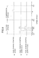
- a fuel direct injection type of multiple cylinder engine 1 equipped with exhaust gas recirculation system which is controlled by the engine control system, is comprised of a cylinder block 3 provided with cylinder bores 2 (only one of which is shown) in which pistons 5 can slide and a cylinder head 4 mounted on the cylinder block 3.
- a combustion chamber 6 is formed in the cylinder by the top of the piston 5, a lower wall of the cylinder head 4 and the cylinder bore 2.
- Two intake ports 12 (only one of which is shown) and one exhaust port 13 are opened into the combustion chamber 6, and are opened and shut at a predetermined timing by intake valves 8 and an exhaust valve 9, respectively.
- a fuel injector 14 is installed into the cylinder head 4 such that a spray of fuel is directly charged into the combustion chamber 6 from the side.
- the piston 5 at its top cavity (not shown) traps the spray of fuel in a later half of a compression stroke to form a stratum of relatively rich air-fuel mixture near the spark plug 10, so as thereby to form a stratified charge of air-fuel mixture in the combustion chamber 6.
- the fuel injector 14 has a wide-angle spray nozzle (not shown) having an angle of spray angle greater than 45°, so that a spray of fuel spreads at a wide angle in the combustion chamber 6 to form a homogeneous distribution of air-fuel mixture during a intake stroke.
- a spark plug 10 is installed in the cylinder head 4 such that electrodes of the spark plug 10 are placed down into the combustion chamber 6 and aligned with the vertical centre line of the cylinder and connected to an ignition circuit 11 to ignite an air-fuel mixture in the combustion engine.
- a fuel line 15, through which the fuel is delivered to the fuel injector 14 from a fuel tank 16 is equipped with two fuel pumps, namely a low pressure fuel pump 17 disposed in the fuel tank 16 and a high pressure fuel pump 18 disposed the outside of the fuel tank 16.
- the fuel line 15 between the fuel pumps 17 and 18 is further equipped with a low pressure regulator 19 and a fuel filter 20 positioned in this order from the side of fuel tank 16.
- a fuel return line 22 equipped with a high pressure regulator 21 is connected to the fuel line 15 between a point after the high pressure fuel pump 18 and a point before the fuel filter 20.
- Fuel is drawn up from the fuel tank 16 by the low pressure pump 17, regulated in pressure by the low pressure regulator 19, and then multiplied in pressurised by the high pressure fuel. pump 18 to the fuel injector 14.
- the high pressurised fuel is partly delivered to the fuel injector 14 and partly returned through the return fuel line 22.
- the high pressure regulator 21 regulates a return fuel quantity so as to optimise the pressurised fuel in pressure level directed to the fuel injector 14.
- An intake line 25 has an air cleaner 26 at the upstream end and an intake manifold at the downstream end which is independently connected to the intake ports 12 of the cylinder.
- An intake valve 8 is provided in each intake port 12 and an air stream control valve 30 is provided either one of the intake ports 12 only.
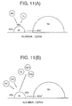
- the air stream control valve 30, which may be of an actuator operated type, causes an air stream to be admitted into the combustion chamber 6 through only the other intake port 12 while it closes, which results in forming, for example, a swirl of intake air abundant in tumble components in a direction of the vertical axis of the cylinder.
- the intake line 25 is provided with a heat sensing type of air-flow sensor 27, an electrically controlled throttle valve 28 and a surge tank 29 in order from the upstream end.
- the throttle valve 28 is not controlled directly by an accelerator pedal but indirectly by an accelerator pedal through an actuator (not shown).
- An exhaust line 31 through which exhaust gas are discharged into the atmosphere is provided with an oxygen sensor (which is hereafter referred to as an O2 sensor) 32, a three-way catalyst 33 and a lean NOx conversion catalyst 34 in order from the upstream end.
- the O2 sensor 32 monitors the oxygen concentration of exhaust gas based on which an air-fuel ratio is determined and provides an output sharply changing between before and after a stoichiometric air-fuel ratio.
- Each of the catalysts 33 and 34 is of a type using a cordierite honeycomb block coated with a catalytic material which allows exhaust gas to flow through.
- the three-way catalyst significantly lowers emission levels of unburnt hydrocarbons (HC), carbon monoxide (CO) and oxides of nitrogen (NOx) while the air-fuel mixture is ⁇ ⁇ 1 and has an excellent catalytic conversion efficiency in, in particular, a window, i.e. in a region of air-fuel ratios close to the stoichiometric air-fuel ratio.
- HC unburnt hydrocarbons
- CO carbon monoxide
- NOx oxides of nitrogen
- the lean NOx conversion catalyst 34 on one hand, adsorbs NOx in exhaust gas while the air-fuel mixture is ⁇ > 1 and, on the other hand, desorbs or releases NOx into exhaust gas for catalysing reduction of NOx while the air-fuel mixture is ⁇ ⁇ 1.
- This type of lean NOx conversion catalyst may be provided by coating a honeycomb block with, for example, a single catalyst layer or double catalyst layers.
- the catalyst may contain noble metals such as platinum (Pt) rhodium (Rh), palladium (Pd) and the like, an alkaline metal such as potassium (K) and the like, and an alkaline-earth metal such as barium (Ba) and the like carried as catalytic metals by alumina or ceria.
- a first or under catalyst layer may be comprised of platinum (Pt) and an alkaline-earth metal such as barium (Ba) and the like carried as catalytic metals by alumina or ceria
- a second or over catalyst layer is comprised of a noble metal such as platinum (Pt) and the like carried as a catalytic metal by zeolite.
- The-three-way catalyst 33 and the lean NOx conversion catalyst 34 may be replaced in position with each other. Further, when employing one of the double catalyst layer types for the lean NOx conversion catalyst 34, the three-way catalyst 33 is not always installed.
- An exhaust gas recirculation (EGR) system 37 is provided to admit exhaust gas partly into the intake line 25.
- the exhaust gas recirculation (EGR) system 37 has a recirculation line extending from the exhaust line 31 upstream the O2 sensor 32 to the intake line 25 between the throttle valve 28 and the surge tank 29, and an electrically operated exhaust gas recirculation (EGR) valve 39 installed to the recirculation line 38 in a position close to the intake line 25.
- the amount of exhaust gas that is recirculated through the recirculation line 38 can be controlled by the EGR valve 39.
- This EGR valve 39 is designed to admit carefully controlled amounts of exhaust gas into the intake air stream.
- a control unit 41 comprising a microcomputer MC.
- Various signals are transferred to the control unit 41 from at least the air-flow sensor 27, the O2 sensor 32, an accelerator position sensor 42 which detects accelerator positions as engine loading, a crank angle sensor 43 which monitors angles of rotation of a crankshaft 7 of the_engine as an engine speed of rotation, a temperature sensor 44 which monitors the temperature of engine cooling water to determine whether the engine 1 is in a cold condition, under a warming up, or in a warm condition, a position sensor (not shown) incorporated in the EGR valve 39 which monitors a valve lift of the EGR valve 39, and an engine starter (not shown).
- the fuel injector 14 is pulsed to open by energising a solenoid according to a pulse width.
- the control unit 41 constantly monitors engine speed, load, throttle position, exhaust, temperature, etc to control the
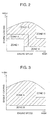
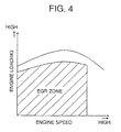
- Figures 2 and 3 show fuel charge control maps with engine speed and loading as parameters for warm engine operations and cold engine operations, respectively, which define a lean fuel charge zone in which the engine is charged with an air-fuel mixture of ⁇ > 1 and an enriched fuel charge zone in which the engine is charged with an air-fuel mixture of ⁇ ⁇ 1 and, in another aspect, a non-split injection zone in which a given amount of fuel is delivered all at once and a split injection zone in which a given amount of fuel is delivered through in two steps or through two split injection.
- the fuel charge control map shown in Figure 2 used while the engine is in a warm condition defines five engine control zones, namely a lean stratified charge zone (I), a lean homogeneous charge zone (II), and an enriched homogeneous charge zones (III) - (V).
- a lean stratified charge zone (I) which is defined for lower engine loading and lower to middle engine speeds, a given amount of fuel is sprayed all at once to cause lean stratified charge combustion immediately before an ignition timing at which the spark plug 10 is fired in a compression stroke.
- lean homogeneous charge zone (II) which is defined for lower to middle engine loading and lower to middle engine speeds
- a given amount of fuel is split into two parts and sprayed in two steps in a intake stroke to cause lean homogeneous charge combustion.
- enriched homogeneous charge zone (III) which is defined for higher engine loading and higher engine speeds
- a given amount of fuel is split into two parts and sprayed in two steps in a intake stroke to cause enriched homogeneous charge combustion.
- enriched homogeneous charge zone (IV) which is defined for higher engine loading and higher engine speeds
- a given amount of fuel is sprayed all at once in a intake stroke to cause enriched homogeneous charge combustion.
- enriched homogeneous charge zone (V) which is defined for lower engine loading and middle to higher engine speeds, a given amount of fuel is sprayed all at once in a intake stroke to cause enriched homogeneous charge combustion. All these zones (I) - (V) are established so as not to overlap one another.
- the fuel charge control map shown in Figure 3 used while the engine is in a cold condition defines three enriched homogeneous charge zones (A), (B) and (C).
- enriched homogeneous charge zone (A) which is defined for middle to higher engine loading and lower to higher engine speeds, a given amount of fuel is split into two parts and sprayed in two-steps in a intake stroke to cause enriched homogeneous charge combustion.
- enriched homogeneous charge zone (B) which is defined for lower engine loading and lower to higher engine speeds
- enriched homogeneous charge zone (C) which is defined for higher engine loading and higher engine speeds
- a given amount of fuel is sprayed all at once in a intake stroke to cause enriched homogeneous charge combustion.
- zones (A) - (C) are established so as not to overlap one another. While the engine operates in any one of the engine control zones (II), (III) and (A) shaded in Figures 2 and 3 in which split injection is made in a intake stroke, the-EGR system 37 is actuated to admit amounts of exhaust gas controlled by the EGR valve 39 into the intake air stream.
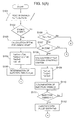
- An exhaust gas recirculation (EGR) rate which is a rate of the amount of exhaust gas that is recirculated relative to the amount of exhaust gas that is produced resulting from combustion varies according to engine speed and loading. As will be described later, is set to 20 to 40 % in this embodiment, which is significantly large as compared with the prior art EGR systems. As shown in Figure 4, an EGR zone may be defined as shaded. The EGR zone covers the lean stratified charge zone (I), the lean homogeneous charge zone (II) and the enriched homogeneous charge zone (III) excepting a higher engine loading region for warm conditions, and the enriched homogeneous charge zone (A) excepting a higher engine loading region for cold conditions.
- EGR exhaust gas recirculation
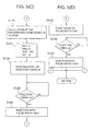
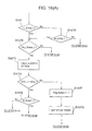
- Figures 5(A) through 5(D) show a flow chart illustrating a sequence routine of fuel charge control.
- step S101 signals Ne, Tv, Qa, Tw and Ss representative of various control factors such as engine speed, accelerator position, intake air quantity, cooling water temperature and a starter signal, respectively, are read into the control unit 41.
- step S102 a decision is made at step S102 as to whether the engine 1 starts.
- an engine start is ascertained.
- an injection pulse width TaK at the engine start is calculated at step S103.
- the given amount of fuel is divided into two parts for early split injection and late split injection made in an intake stroke according to a split ratio represented by a split factor c (1 > 0).
- the injection pulse width TaK is divided into two split injection pulse widths TaK1 which is expressed by c x TaK and TaK2 which is expressed by (1 - c) x TaK at step S104.
- a given amount of fuel is neither sprayed in non-split intake stroke injection nor in non-split compression stroke injection, and simultaneously both non-split intake stroke injection pulse width TaK3 and non-spilt compression stroke injection pulse width TaD are set to 0 (zero).
- split injection timings s1 and s2 for the early and late split injection are determined, respectively, at step S105.
- the early and late split injection timings s1 and s2 are predetermined. That is, the early split injection timing s1 for the early split injection is dictated by an angle of rotation of the crankshaft 7 in an early half of a intake stroke and, more specifically, at a crank angle 45 to 50 degrees before top-dead-centre in a intake stroke, and the late split injection is timed to start at a point s2 in a later half of the intake stroke and, more specifically, at a crank angle 100 to 120 degrees after top-dead-centre in the intake stroke.
- step S117 After the determination of early and late split injection timings s1 and s2 at step S105, a decision is made at step S117 as to whether it is the early split injection timing s1 for the early split injection. After waiting up to the early split injection timing s1 at step S117, the fuel injector 14 is pulsed to open to deliver the amount of fuel depending upon the early split injection pulse width TaK1 at step S118. Similarly, a decision is subsequently made at step S119 as to whether it is the late split injection timing s2 for the late split injection. After waiting up to the late split injection timing s2 at step S119, the fuel injector 14 is pulsed to open to deliver the amount of fuel depending upon the late split injection pulse width TaK2 at step S120. After a conclusion of the late split injection at step S120, the flow chart logic returns to restart the sequence routine.
- step S106 another decision is made at step S106 as to whether the cooling water temperature Tw is higher than a specified value Two, i.e. whether the engine 1 is in a warm condition.
- step S107 still another decision is made at step S107 as to whether the engine operating condition is in the lean stratified charge zone (I) for lower engine loading and middle to higher engine speeds of the fuel charge control map for warm engine operation shown in Figure 2.
- a non-split compression stroke injection pulse width TaD for the lean stratified charge combustion is calculated at step S108.
- both split injection pulse widths Tak1 and Tak2 and non-split intake stroke injection pulse width TaK3 are set to 0 (zero) at step S109.
- a non-split compression stroke injection timing s3 is determined at step S110. As shown by (a) in Figure 6, the non-split compression stroke injection timing s3 is predetermined. That is, the non-split compression stroke injection timing s3 is set in a later half of a compression stroke. Subsequently, a decision is made at step S111 as to whether it is the injection timing s3 for the non-split compression stroke injection.
- the fuel injector 14 After waiting up to the non-split compression stroke injection timing s3 at step S111, the fuel injector 14 is pulsed to open to deliver the amount of fuel depending upon the non-split compression stroke injection width TaD at step S112. After a conclusion of the non-split compression stroke injection, the flow chart logic returns to restart the sequence routine.
- step S113 When the answer to the decision as to engine operating condition made at step S107 is negative, another decision is subsequently made at step S113 as to whether the engine operating condition is in the lean homogeneous charge zone (II) for lower engine loading and lower to middle engine speeds of the fuel charge control map for warm engine operation shown in Figure 2.
- an injection pulse width TaK for lean homogeneous charge combustion is calculated at step S114.
- the given amount of fuel is divided into two parts for early and late split injection made in a intake stroke according to a split ratio represented by a split factor a (1 > 0) at step S115.
- the injection pulse width TaK is divided into an early split injection pulse width TaK1 which is expressed by a x TaK and a late split injection pulse width TaK2 which is expressed by (1 - a) x TaK.
- the given amount of fuel is neither sprayed in non-split intake stroke injection nor in non-split compression stroke injection and consequently both non-split intake stroke injection pulse width TaK3 and non-spilt compression stroke injection pulse width TaD are set to 0 (zero).
- early and late split injection timings s1 and s2 are determined as shown by (b) in Figure 6 at step S116.
- the fuel injector 14 After waiting up to the early split injection timing s1 at step S117, the fuel injector 14 is pulsed to open to deliver the amount of fuel depending upon the early split injection pulse width TaK1 at step S118.
- the fuel injector 14 After waiting up to the late split injection timing s2 at step S119, the fuel injector 14 is pulsed to open to deliver the amount of fuel depending upon the late split injection pulse width TaK2 at step S120.
- the flow chart logic After a conclusion of the late split injection at step S120, the flow chart logic returns to restart the sequence routine.
- step S121 When the engine operating condition is out of the lean homogeneous charge zone (II), another decision is subsequently made at step S121 as to whether the engine operating condition is in the enriched homogeneous charge zone (III) for middle to higher engine loading and lower to higher engine speeds of the fuel charge control map for warm engine operation shown in Figure 2.
- an injection pulse width TaK for enriched homogeneous charge combustion is calculated at step S122.
- the given amount of fuel is divided into two parts for the early and late split injection-made in a intake stroke according to a split ratio represented by a split factor b (1 > 0) at step S123.
- the injection pulse width TaK is divided into an early split injection pulse width TaK1 which is expressed by b x TaK and a late split injection pulse width TaK2 which is expressed by (1 - b) x TaK.
- the given amount of fuel is sprayed neither in non-split intake stroke injection nor in non-split compression stroke injection and -consequently both non-split intake stroke injection pulse width TaK3 and non-spilt compression stroke injection pulse width TaD are set to 0 (zero).
- early and late split injection timings s1 and s2 are determined as shown by (b) in Figure 6 at step S124.
- the fuel injector 14 After waiting up to the early split injection timing s1 at step S117, the fuel injector 14 is pulsed to open to deliver the amount of fuel depending upon the early split injection pulse width TaK1 at step S118. Similarly, after waiting up to the late split injection timing s2 at step S119, the fuel injector 14 is pulsed to open to deliver the amount of fuel depending upon the late split injection pulse width TaK2 at step S120. After a conclusion of the late split injection at step S120, the flow chart logic returns to restart the sequence routine.
- an injection pulse width TaK for enriched homogeneous charge combustion is calculated at step S126.
- the injection pulse width TaK is employed as a non-split intake stroke injection pulse width TaK3 at step S127.
- both split injection pulse widths Tak1 and Tak2 and non-split compression stroke injection pulse width TaD are set_to 0 (zero).
- a non-split intake stroke injection timing s4 is determined at step S128.
- the non-split intake stroke injection timing s4 is predetermined. That is, the non-split intake stroke injection timing s4 is set such that the non-split intake stroke injection is started at approximately the midpoint of a intake stroke.
- the fuel injector 14 is pulsed to open to deliver the amount of fuel depending upon the non-split intake stroke injection width TaK3 at step S130.
- the flow chart logic After a conclusion of the non-split intake stroke injection, the flow chart logic returns to restart the sequence routine.
- step S106 when the answer to the decision as to cooling water temperature Tw made at step S106 is negative, this indicates that the engine 1 is still in a cold condition, then, another decision is subsequently made at step S125 as to whether the engine operating condition is in the enriched homogeneous charge zone (A) for middle to middle to higher engine loading of the fuel charge control map for cold engine operation shown in Figure 3.
- steps S122-S124 and S117 through S120 are taken to cause early and late split infection in a intake stroke to deliver the given amounts of fuel depending upon the early and late split injection pulse widths TaK1 and TaK2.
- the fuel injector 14 After waiting up to the non-split intake stroke injection timing s4 at step S129, the fuel injector 14 is pulsed to open to deliver the amount of fuel depending upon the non-split intake stroke injection-width TaK3 at step S130. After a conclusion of the non-split intake stroke injection, the flow chart logic returns to restart the sequence routine.
- the midpoint m between the early and late split injection timings s1 and s2 is positioned before the midpoint of a intake stroke which is at a crank angle 90 degrees after top-dead-centre.
- Each injection pulse split factor a, b, c is set approximately 0.5, which divides a given amount of fuel into two exact halves for early and late split injection.
- Figure 7 shows a flow chart illustrating a sequence routine of exhaust gas recirculation control by controlling the EGR valve 39.
- step S201 signals Ne, Tv, Qa, Tw, Lv and Ss representative of various control factors such as engine speed, accelerator position, intake air quantity, cooling water temperature, EGR valve lift and a starter signal, respectively, are read into the control unit 41.
- step S202 a decision is made at step S202 as to whether the engine 1 starts. When there is an occurrence of a starter -signal Ss and the engine speed Ne is lower than a specified speed, an engine start is ascertained. When the answer is affirmative, the flow chart logic returns to restart the sequence routine.
- step S203 another decision is made at step S203 as to whether the cooling water temperature Tw is higher than the specified value Two, i.e. whether the engine 1 is in a warm condition.
- step S204 still another decision is made at step S204 as to whether the engine operating condition is in the lean homogeneous charge zone (II) for lower to middle engine loading and lower to middle to higher engine speeds of the fuel charge control map for warm engine operation shown in Figure 2.
- the engine operating condition i.e. the engine loading and speed
- a target valve lift Lv(LHW) of the EGR valve 39 for lean homogeneous charge combustion for warm engine operation is calculated at step S205.
- step S207 another decision is made at step S207 as to whether the engine operating condition is in the enriched homogeneous charge zone (III) for middle to higher engine loading of the fuel charge control map for warm engine operation shown in Figure 2.
- a target EGR valve lift Lv(RHW) of the EGR valve 39 for enriched homogeneous charge combustion for warm engine operation is calculated at step S208.
- step S209 another decision is made at step S209 as to whether the engine operating condition is in the enriched homogeneous charge zone (A) for middle to higher engine loading of the fuel charge control map for cold engine operation shown in Figure 3.
- the engine operating condition i.e. the engine loading and speed
- a target EGR valve lift Lv(LHC) of the EGR valve 39 for lean homogeneous charge combustion for cold engine operation is calculated at step S210.
- the EGR valve 39 is actuated to admit exhaust gas into an intake air stream according to the valve lift Lv(LHW), Lv(RHW) or Lv(LHC) at step S206.
- the flow chart logic returns to restart the sequence routine.
- the flow chart logic returns to restart the sequence routine without recirculating exhaust gas.
- a given amount of fuel is sprayed all at once in a compression stroke as shown by (a) in Figure 6 when the engine 1 operates in the lean stratified homogeneous charge zone (I) for lower engine loading and lower to middle engine-speeds or in a intake stroke as shown by (c) in Figure 6 when the engine 1 operates in the enriched homogeneous charge zone (IV) for higher engine loading and higher engine speeds or in the enriched homogeneous charge zone (V) for lower engine loading and middle to higher engine speeds.
- the engine operates in the zone in which a given amount of fuel is sprayed through early and late split injection in a intake stroke, i.e.
- the EGR valve 39 is actuated to admit exhaust gas in the exhaust line 31 partly into an intake air stream in the intake line 25.
- the exhaust gas recirculation (EGR) rate is significantly low while the engine operates with higher loading in the enriched homogeneous charge zone (A) and the enriched homogeneous charge zone (III).
- the EGR valve 39 may be shut in the higher loading zone as shown in Figure 4.
- the part of fuel sprayed through the early split injection is homogeneously diffused in the combustion chamber 6 with an increase in volume of the combustion chamber 6 following a down stroke of the piston 5 before the late split injection.
- the part of fuel splayed through the late split injection is diffused, so as to provide a homogeneous distribution of air-fuel mixture in the entire combustion chamber 6. That is, the split injection provides a homogeneous distribution of air-fuel mixture in the entire combustion chamber 6 without enhancing penetrating force of a spray of fuel.
- the early and late split injection which is shifted as one whole a little to the early side of a intake stroke prevents or significantly reduces sticking of sprayed fuel through the late split injection to the side wall of the cylinder bore 2 when the piston 5 reaches near bottom-dead-centre or at the end of a intake stroke, which is always desirable for a homogeneous distribution of fuel in the combustion chamber 6.
- sprayed fuel moderated in penetrating force through the split injection prevents sprayed fuel from sticking to the side wall of the cylinder bore 2.
- the air stream control valve 30 is actuated to admit intake air into the combustion chamber 6 through one of the intake ports 12 only with an effect of producing a swirl of intake air which causes an accelerated homogeneous distribution of fuel and accelerated evaporation of fuel in the combustion chamber 6.
- the mutually potentiating effect of the acceleration of a homogeneous distribution of fuel and evaporation of fuel provides a big raise in combustion velocity, so as to improve specific fuel consumption due to a reduction in combustion time and increase combustion stability of the engine 1.
- the Pi coefficient variation and the specific fuel consumption are reduced even more greatly when the late split injection is advanced so as to end before an crank angle of 120° after top-dead centre.
- the late split injection is made in a condition where the piston 5 moves down with the highest speed with an effect of causing an intake air stream to enter with the highest speed, a spray of fuel through the late split injection is homogeneously distributed in the combustion chamber 6 by the intake air stream, which provides the improvement of combustion stability and specific fuel consumption.
- the timing of early split injection s1 is fixed at crank angle of 20° after top-dead centre
- the timing of late split injection s2 is fixed at crank angle of 70° after top-dead centre.
- the significantly great improvement of combustion stability yields an increase in the amount of recirculated exhaust gas which is significantly large as compared to the prior art fuel charge control.
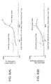
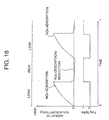
- measurements of the Pi coefficient variation following a change in exhaust gas recirculation (EGR) rate changing from 0 to 60 % were made as to the case where the engine 1 was operated with a stoichiometric mixture. The result is shown together with the Pi coefficient variation resulting from non-split injection control in Figure 10.
- the non-split injection expands the upper limit of exhaust gas recirculation (EGR) rate as high as 40 % or higher, it is permitted to set the exhaust gas recirculation (EGR) rate to approximately 25 %.
- the early and late split injection expand the upper limit of exhaust gas recirculation (EGR) rate as high as 60 % or higher, it is permitted to set the exhaust gas recirculation (EGR) rate to approximately 40 % even-taking account of fluctuations in the amount of practically recirculated exhaust gas due to a delay in operation of the EGR valve 39.
- Figure 10 further shows specific fuel consumption, the amount of NOx formation, HC concentration ratio (HC/NOx) (which refers to a ratio of hydrocarbon concentration relative to nitrogen oxides concentration) with respect to exhaust gas recirculation (EGR) rate.
- EGR exhaust gas recirculation
- EGR exhaust gas recirculation
- the emission level of NOx lowers gradually, but sharply particularly in the extent of exhaust gas recirculation (EGR) rate between 0 and 40 %, with an increase in the amount of recirculated exhaust gas.
- the HC concentration ratio NC/NOx increases gradually, but sharply particularly in the extent of exhaust gas recirculation (EGR) rate higher than 40 %, with an increase in the amount of recirculated exhaust gas.
- the-NOx concentration becomes higher than the HC concentration in the extent of exhaust gas recirculation (EGR) rate between 0 and 40 %, as a result of which a change in-HC concentration ratio (HC/NOx) becomes smaller relative to a change in NOx concentration and that the NOx concentration becomes lower than the HC concentration in the extent of exhaust gas recirculation (EGR) rate above 40 %, as a result of which a change in HC concentration ratio (HC/NOx) becomes greater relative to a change in NOx concentration.
- EGR exhaust gas recirculation
- the improvement of specific fuel consumption and a significant reduction in the amount of NOx formation are realised by controlling the EGR valve 39 so as to admit exhaust gas with an exhaust gas recirculation (EGR) rate higher than 20 %, for example with a maximum exhaust gas recirculation (EGR) rate of 40 %.
- EGR exhaust gas recirculation
- the improvement of specific fuel consumption and a significant reduction in the amount of NOx formation are realised by performing the split injection control and recirculating exhaust gas with an exhaust gas recirculation (EGR) rate higher than 20 %, for example with a maximum exhaust gas recirculation (EGR) rate of 40 %.
- EGR exhaust gas recirculation
- the HC concentration ratio (HC/NOx) becomes higher with progress of fuel combustion, refreshing the lean NOx conversion catalytic 34 is accelerated without increasing the air-fuel ratio so low.
- the lean NOx conversion catalyst works as follows:
- Figures 12(A) and 12(B) show, respectively, specific fuel consumption and HC concentration ratio (HC/NOx) relative to exhaust gas recirculation (EGR) rate when the air-fuel ratio is fixed at 14.7 (stoichiometric ratio) and specific fuel consumption and HC concentration ratio (HC/NOx) relative to air-fuel ratio when the exhaust gas recirculation (EGR) rate is fixed at 0 %. It has been known in the art that refreshing the lean NOx conversion catalyst can be sufficiently accelerated by rising the air-fuel ratio (A/F) up to approximately 12.
- the split injection in the enriched homogeneous zone (III) for middle to higher engine loading, is extremely effective to elevate the combustion stability of the engine 1 and provides a maximum permissible exhaust gas recirculation (EGR) rate of approximately 40 %.
- EGR exhaust gas recirculation
- Figures 13 and 14 show flow charts illustrating sequence routines of fuel charge control and exhaust gas recirculation control according to another embodiment of the invention, respectively.
- the flow chart logic shown in Figure 13 is similar to the flow chart logic shown in Figures 5(A) through 5(D) but incorporates a decision block at step S106A between the decision blocks at step S106 and S107.
- the split injection is executed together with exhaust gas recirculation during acceleration as well as while the engine 1 operates in any one of the fuel charge zones (II), (III) and (A) in order to refresh the lean NOx conversion catalyst 34.
- the cooling water temperature Tw is higher than the specified value Two at step S106, this indicates that the engine 1 is in a warm condition, then a decision is made at step S106A as to whether the engine is under acceleration.
- step S107 the control proceeds to steps S108 through S112 or steps S113 through S120 or steps S113, S121-S122 and S117 through S120 after the decision as to the lean stratified charge zone (I) for lower engine loading and lower to middle engine speeds of the fuel charge control map for warm engine operation (see Figure 2) made at step S107.
- Figure 14 shows a flow chart illustrating a sequence routine of exhaust gas recirculation control by controlling the EGR valve 39 according to another embodiment of the invention.
- step S301 signals Ne, Tv, Qa, Tw, Lv and Ss representative of various control factors such as engine speed, accelerator position, intake air quantity, cooling water temperature, EGR valve lift and a starter signal, respectively, are read into the control unit 41.
- step S302 a decision is made at step S302 as to whether the engine 1 starts.
- a starter signal Ss When there is an occurrence of a starter signal Ss and the engine speed Ne is lower than a specified speed, an engine start is ascertained.
- the flow chart logic returns to restart the sequence routine.
- step S303 another decision is made at step S303 as to whether the cooling water temperature Tw is higher than the specified value Two, i.e. whether the engine 1 is in a warm condition.
- a decision is subsequently made at step S304 as to whether the engine 1 is under acceleration.
- a specified accelerator position Tvo or a specified engine speed Neo is detected, it is decided that the engine 1 is under acceleration.
- step S305 a decision is made at step S305 as to whether the engine operating condition is in the lean stratified charge zone (I) for lower engine loading and lower to middle to higher engine speeds of the fuel charge control map for warm engine operation shown in Figure 2.
- a target valve lift Lv(LSW) of the EGR valve 39 for lean stratified charge combustion for warm engine operation is calculated at step S306.
- a decision is made at step S308 as to whether the engine operating condition is in the lean homogeneous charge zone (II) for lower to middle engine loading and lower to middle to higher engine speeds of the fuel charge control map for warm engine operation shown in Figure 2.
- a target valve lift Lv(LHW) of the EGR valve 39 for lean homogeneous charge combustion for warm engine operation is calculated at step S309.
- another decision is made at step S310 as to whether the engine operating condition is in the enriched homogeneous charge zone (III) for middle to higher engine loading of the fuel charge control map for warm engine operation shown in Figure 2.
- a target EGR valve lift Lv(RHW) of the EGR valve 39 for enriched homogeneous charge combustion for warm engine operation is calculated at step S311.
- step S312 when the answer to the decision as to cooling water temperature Tw made at step S303 is negative or the answer to the decision as to acceleration made at step S304 is affirmative, another decision is made at step S312 as to whether the engine operating condition is in the enriched homogeneous charge zone (A) for middle to higher engine loading of the fuel charge control map for cold engine operation shown in Figure 3.
- the engine operating condition i.e. the engine loading and speed
- a target EGR valve lift Lv(LHC) of the EGR valve 39 for lean homogeneous charge combustion for cold engine operation is calculated at step S313.
- the EGR valve 39 is actuated to admit exhaust gas into an intake air stream according to the valve lift Lv(LSW), Lv(LHW), Lv(RHW) or Lv(LHC) at step S307.
- the flow chart logic returns to restart the sequence routine. Further, when the answer to the decision made at step S302 is affirmative or when the answer to any one of the decisions made at steps S310 and S312 is negative, the flow chart logic returns to restart the sequence routine without recirculating exhaust gas.
- the lean NOx conversion catalyst 34 is expeditiously refreshed by executing the split injection and admitting a large amount of exhaust gas recirculation.
- Figure 15 shows the amount of NOx formation relative to vehicle speed as a result of actual running test of a vehicle on which the engine 1 equipped with the fuel charge control system of the embodiment shown in Figures 13 and 14 was mounted.
- the amount of NOx formation resulting from non-split injection together with exhaust gas recirculation control is shown by a solid line and the amount of NOx formation resulting from split injection is shown by a broken line.
- the vehicle used in the test was equipped with a double layered NOx conversion catalyst which has a NOx adsorption catalytic layer and a layer of catalysing reduction of NOx in the exhaust line.
- the lean NOx conversion catalyst 34 After second acceleration of the vehicle, the lean NOx conversion catalyst 34 experiences a rise in temperature accompanying a rise in exhaust gas temperature and causes a gradual decline in catalytic conversion efficiency, as a result of which the amount of NOx formation rises. Even in such an event, due to the refreshment of the lean NOx conversion catalyst 34 during the prior acceleration, the amount of NOx formation is controlled to be lower as compared to the case where fuel is sprayed through non-split injection. In this manner, when the engine 1 is operated with a enriched air-fuel mixture, the HC concentration ratio is greatly risen with an effect of refreshing the lean NOx conversion catalyst 34. As a result, the air-fuel ratio can be lowered by that extent during refreshing the lean NOx conversion catalyst 34.
- the air-fuel ratio may be altered to a stoichiometric ratio of 14.7 to prevent aggravation of specific fuel consumption and significantly reduces shocks on the driver without restricting a refreshing action on the lean NOx conversion catalyst 34. Even if there occurs a change in engine output due to an alteration of air-fuel ratio, there is no unpleasant shocks exerting on the driver because the change in engine output does not result from acceleration.
- Figures 16(A), 16(B) and 17 show flow charts illustrating sequence routines of fuel charge control and exhaust gas recirculation control according to another embodiment of the invention, respectively.
- the flow chart logic is similar to the flow chart logic shown in Figures 5(A) through 5(D) or Figure 13 but incorporates step S107A through S107G between the decision blocks at step S107 and S108 and steps S131 and S132 after the function blocks at steps S120 and S130.
- the split injection is executed together with exhaust gas recirculation during acceleration as well as while the engine 1 operates in any one of the fuel charge zones (II), (III) and (A) in order to refresh-the lean NOx reduction conversion catalyst 34 and the fuel charge with which the engine 1 is operated is forcibly enriched to prevent aggravation of catalytic conversion efficiency of the lean NOx conversion catalyst 34 when the amount of NOx adsorbed by the lean NOx conversion catalyst 34 increases due to engine operation with a lean stratified charge continuing for a specified period of time.
- the enriching flag FlagSpike provides an indication of a demand for enriching a fuel charge when it is up or has been set to a state of "1" or an indication that there is no demand for enriching a fuel charge when it is down.
- the flow chart logic proceeds to the decision as to the enriched homogeneous charge zone (A) at step S125 (see Figure 5(C)).
- step S107C a calculation is made at step S107C to estimate the amount of NOx (fNOx) adsorbed by the lean NOx conversion-catalyst 34 based on engine operating condition and operating time. Subsequently, the estimated amount of adsorbed NOx (fNOx) is compared with-a specified value (fNOxo) at step S107D. When the estimated amount of adsorbed NOx (fNOx) is less than the specified value (fNOxo), a decision is further made at step S107E as to whether the engine 1 operates in the lean stratified charge zone (I). When the answer is affirmative, the flow chart logic proceeds to the function block at step S108 (see Figure 5(A)).
- the flow chart logic proceeds to the function block at step S114 (see Figure 5(B)). Further, when the estimated amount of adsorbed NOx (fNOx) is greater than the specified value (fNOxo), the enriching flag FlagSpike is set to the state of "1" at step S107F, and a spike timer is set at step S107G. This spike timer is reset when counts up a specified time after a conclusion of enriching a fuel charge. When the enriching flag FlagSpike is down at step S107B or after setting the spike timer at step S107G, the flow chart logic proceeds to the function block for a decision as to the enriched homogeneous charge zone (A) at step S125 (see Figure 5(B)).
- step S131 As shown in Figure 16(B), after execution of late split injection with a pulse width TaK2 at step S120 or non-split intake stroke injection with a pulse width TaK3 at step S130, a decision is made at step S131 as to whether the spike timer has been reset. Thereafter, the flow chart logic returns to restart the fuel charge control sequence routine when the spike timer has not yet reset or after resetting the enriching flag FlagSpike down at step S132 when the spike timer has reset.
- the fuel charge control when it is decided that the estimated amount of NOx adsorption (fNOx) exceeds the specified value (fNOxo), the fuel charge is forcibly enriched to make the lean NOx conversion-catalyst 34 refreshed and the split injection is continuously executed until the specified time passes.
- the spike timer has counted the specified time and is reset, the fuel injection control is performed in the same sequence routine as illustrated by the flow chart shown in Figures 5(A) through 5(D).
- the flow chart logic is similar to the flow chart logic shown in Figure 13 excepting decision as to acceleration at step S303 with a decision as to enriching flag FlagSpike at step S303'.
- Figure 19 show a fuel charge control map for cold engine operation which is similar to that shown in figure 2 but has an enriched homogeneous charge zone (IV) is expanded above an enriched homogeneous charge zone (III).
- the exhaust gas recirculation control is executed while the engine operates in the EGR zone shown in Figure 14 which covers the lean stratified charge zone (I), the lean homogeneous charge zone (II) and the enriched homogeneous charge zone (III).
- Figure 20 show a fuel charge control map for cold engine operation which is suitably used for fuel charge control of a direct injection-spark ignition engine of a type which does not have a stratified charge combustion feature.
- the fuel charge control map is similar to that shown in Figure 19 but, while having no lean stratified charge zone (I), defines an enriched homogeneous charge zone (V) lying over possible engine speeds in which non-split injection is executed.
- This type of direct injection-spark ignition engine has no necessity of having a piston formed with a top cavity and provides a reduction in heat loss consequently.
- a given amount of fuel may be divided into three parts or more. In such a case, it is desirable to start the last split injection at a point in a first division or a middle division of three divisional parts of a intake stroke.
- HC/NOx HC concentration ratio
- the HC concentration ratio (HC/NOx) of exhaust gas is sufficiently risen to refresh the lean NOx conversion catalyst 34 to some extent while the refreshing action is inferior to the above described embodiments.
- a decline in NOx concentration causes a rise in CO concent-ration ratio (CO/NOx) as well as a rise in HC concentration ratio (HC/NOx), providing an even more enhanced refreshing action on the lean NOx conversion catalyst.
- a high HC concentration ratio (HC/NOx) of exhaust gas accelerates reduction of NOx, so to stabilise performance of a NOx reduction type catalyst as well as a NOx absorption type catalyst.
- the fuel charge is forcibly enriched to make the lean NOx conversion catalyst refreshed when the estimated amount of NOx adsorption (fNOx) exceeds the specified value (fNOxo), it may be enriched when the engine is continuously operated with a lean fuel charge, specifically in the lean stratified charge zone (I) or the lean homogeneous charge zone (II), for a specified period of time.
Landscapes
- Engineering & Computer Science (AREA)
- Chemical & Material Sciences (AREA)
- Combustion & Propulsion (AREA)
- Mechanical Engineering (AREA)
- General Engineering & Computer Science (AREA)
- Electrical Control Of Air Or Fuel Supplied To Internal-Combustion Engine (AREA)
- Combustion Methods Of Internal-Combustion Engines (AREA)
Claims (8)
- Système de commande de moteur destiné à un type de moteur à allumage par étincelle à injection directe (1) qui est équipé d'un injecteur de carburant (14) pour pulvériser du carburant directement dans une chambre de combustion (6), d'un système d'admission (25) et d'un système d'échappement (31) comportant un catalyseur de conversion de NOx pauvre (34) destiné à abaisser un niveau d'émission des oxydes d'azote (NOx) dans le gaz d'échappement à un rapport air-carburant de λ > 1 pour commander le moteur (1) pour qu'il fonctionne avec une charge de carburant de λ > 1 dans une zone de charge partielle du moteur et avec une charge de carburant de λ < 1 dans une zone de charge enrichie autre que ladite zone de charge partielle du moteur, ledit système de commande du moteur comprenant :caractérisé parun moyen de surveillance d'état de fonctionnement du moteur (41) destiné à surveiller des états de fonctionnement du moteur, etun moyen de recirculation de gaz d'échappement (37) destiné à faire partiellement recirculer le gaz d'échappement dans ledit système d'admission (25) depuis ledit système d'échappement (31),
un moyen de commande d'injection de carburant (41) destiné, tandis que ledit moyen de surveillance d'état de fonctionnement du moteur (41) surveille les états de fonctionnement du moteur dans ladite zone de charge enrichie, à diviser une quantité donnée de carburant en au moins deux parties qui sont délivrées par intermittence par l'intermédiaire d'injections séparées antérieure et postérieure dans un temps d'admission d'un piston de cylindre (5) respectivement et à amener ledit moyen de recirculation de gaz d'échappement (37) à faire recirculer le gaz d'échappement dans un flux d'air d'admission introduit dans ledit système d'admission (25) depuis ledit système d'échappement (31) tandis que ledit injecteur de carburant (14) exécute ladite injection séparée. - Système de commande de moteur selon la revendication 1, dans lequel ledit moyen de commande d'injection de carburant (41) commande ledit moyen de recirculation du gaz d'échappement (37) pour faire recirculer le gaz d'échappement dans ledit flux d'air d'admission à un taux d'une quantité du gaz d'échappement qui est mis en recirculation par rapport à une quantité du gaz d'échappement qui est produit à la suite d'une combustion, supérieur à 20 %.
- Système de commande de moteur selon la revendication 1 ou 2, dans lequel le moyen de commande d'injection de carburant (37) amène l'injecteur de carburant (14) à exécuter des injections séparées tandis que le moyen de surveillance d'état de fonctionnement du moteur (41) surveille un état d'accélération.
- Système de commande de moteur selon la revendication 1, 2 ou 3, dans lequel le moyen de commande d'injection de carburant (41) enrichit une charge de carburant lorsque le moteur (1) est mis en oeuvre de façon continue avec une charge de carburant pauvre pendant un intervalle de temps spécifié et amène ledit injecteur de carburant (14) à exécuter ladite injection séparée tandis que le moteur est mis en oeuvre avec ladite charge de carburant enrichie.
- Système de commande de moteur selon la revendication 4, dans lequel ledit moyen de commande d'injection de carburant (41) modifie ladite charge de carburant enrichie en une charge de carburant pauvre après l'écoulement d'un intervalle de temps spécifié depuis que la charge de carburant est enrichie.
- Système de commande de moteur selon la revendication 1, dans lequel ledit moyen de commande d'injection de carburant (41) commande ladite charge de carburant à approximativement un rapport air-carburant stoechiométrique dans ladite zone de charge enrichie.
- Système de commande de moteur selon la revendication 1, comprenant en outre un moyen de commande de flux d'air (30) destiné à créer un flux d'air dans ladite chambre de combustion (6).
- Système de commande de moteur selon la revendication 1, dans lequel ledit injecteur de carburant présente un angle de pulvérisation supérieur à approximativement 45°.
Applications Claiming Priority (6)
| Application Number | Priority Date | Filing Date | Title |
|---|---|---|---|
| JP324730/97 | 1997-11-26 | ||
| JP32473097 | 1997-11-26 | ||
| JP32473097 | 1997-11-26 | ||
| JP27462798A JP3945040B2 (ja) | 1997-11-26 | 1998-09-29 | エンジンの制御装置 |
| JP274627/98 | 1998-09-29 | ||
| JP27462798 | 1998-09-29 |
Publications (3)
| Publication Number | Publication Date |
|---|---|
| EP0919714A2 EP0919714A2 (fr) | 1999-06-02 |
| EP0919714A3 EP0919714A3 (fr) | 2001-04-11 |
| EP0919714B1 true EP0919714B1 (fr) | 2004-05-06 |
Family
ID=26551119
Family Applications (1)
| Application Number | Title | Priority Date | Filing Date |
|---|---|---|---|
| EP98309723A Expired - Lifetime EP0919714B1 (fr) | 1997-11-26 | 1998-11-26 | Système de commande d'injection directe dans un moteur à combustion à allumage commandé |
Country Status (4)
| Country | Link |
|---|---|
| EP (1) | EP0919714B1 (fr) |
| JP (1) | JP3945040B2 (fr) |
| KR (1) | KR100589805B1 (fr) |
| DE (1) | DE69823616T2 (fr) |
Families Citing this family (12)
| Publication number | Priority date | Publication date | Assignee | Title |
|---|---|---|---|---|
| JP2000073817A (ja) * | 1998-08-28 | 2000-03-07 | Toyota Motor Corp | 内燃機関の排気浄化装置 |
| US6257197B1 (en) * | 1998-09-29 | 2001-07-10 | Mazda Motor Corporation | Control system for a direct injection-spark ignition engine |
| US6055956A (en) * | 1998-09-29 | 2000-05-02 | Mazda Motor Corporation | Control system for an engine equipped with exhaust gas recirculation system |
| DE10031875A1 (de) * | 2000-06-30 | 2002-01-10 | Bosch Gmbh Robert | Zündverfahren und entsprechende Zündvorrichtung |
| DE10258572B4 (de) * | 2002-12-14 | 2009-09-03 | Audi Ag | Verfahren zum Betreiben einer Brennkraftmaschine eines Fahrzeugs, insbesondere eines Kraftfahrzeuges |
| DE10360004A1 (de) * | 2003-12-19 | 2005-07-21 | Robert Bosch Gmbh | Verfahren zum Betrieb eines 4-Taktmotors |
| JP2007224753A (ja) * | 2006-02-21 | 2007-09-06 | Mazda Motor Corp | 火花点火式直噴エンジン |
| EP1847704B1 (fr) * | 2006-04-19 | 2010-03-17 | Delphi Technologies, Inc. | Procédé et dispositif de commande d'une système d'injection de carburant |
| JP4715687B2 (ja) * | 2006-09-13 | 2011-07-06 | トヨタ自動車株式会社 | 筒内噴射式火花点火内燃機関 |
| AT508578B1 (de) | 2010-10-07 | 2012-08-15 | Avl List Gmbh | Verfahren zum betreiben einer viertakt-brennkraftmaschine mit funkenzündung |
| JP6305106B2 (ja) * | 2014-02-27 | 2018-04-04 | 株式会社Subaru | 燃料噴射制御装置 |
| CN116398311B (zh) * | 2023-06-07 | 2023-08-18 | 潍柴动力股份有限公司 | 多策略燃料喷射方法、装置、设备和汽车 |
Family Cites Families (8)
| Publication number | Priority date | Publication date | Assignee | Title |
|---|---|---|---|---|
| EP0560991B9 (fr) | 1991-10-03 | 2005-01-26 | Toyota Jidosha Kabushiki Kaisha | Dispositif pour purifier les gaz d'echappement d'un moteur a combustion interne |
| EP0621400B1 (fr) * | 1993-04-23 | 1999-03-31 | Daimler-Benz Aktiengesellschaft | Moteur à combustion interne à injection et à compression d'air avec un dispositif pout traiter les gaz d'échappement à fin de réduire les oxides azoté |
| JP3186373B2 (ja) | 1993-10-18 | 2001-07-11 | トヨタ自動車株式会社 | 筒内噴射式火花点火機関 |
| EP1136685B1 (fr) * | 1993-12-28 | 2004-06-16 | Hitachi, Ltd. | Dispositif et méthode de commande de moteur à combustion interne |
| JPH07217478A (ja) | 1994-01-28 | 1995-08-15 | Toyota Motor Corp | 筒内噴射式火花点火機関の燃料噴射制御装置 |
| US5775099A (en) * | 1994-04-12 | 1998-07-07 | Toyota Jidosha Kabushiki Kaisha | Method of purifying the exhaust of an internal combustion engine |
| DE69520567T2 (de) * | 1995-01-20 | 2001-08-23 | Toyota Jidosha K.K., Toyota | Abgasreinigungsverfahren für eine brennkraftmaschine |
| WO1997011269A1 (fr) * | 1995-09-22 | 1997-03-27 | Robert Bosch Gmbh | Procede et dispositif de commande d'un moteur a combustion interne |
-
1998
- 1998-09-29 JP JP27462798A patent/JP3945040B2/ja not_active Expired - Fee Related
- 1998-11-25 KR KR1019980050734A patent/KR100589805B1/ko not_active IP Right Cessation
- 1998-11-26 EP EP98309723A patent/EP0919714B1/fr not_active Expired - Lifetime
- 1998-11-26 DE DE69823616T patent/DE69823616T2/de not_active Expired - Lifetime
Also Published As
| Publication number | Publication date |
|---|---|
| KR19990045571A (ko) | 1999-06-25 |
| KR100589805B1 (ko) | 2006-08-30 |
| DE69823616D1 (de) | 2004-06-09 |
| EP0919714A2 (fr) | 1999-06-02 |
| JP3945040B2 (ja) | 2007-07-18 |
| EP0919714A3 (fr) | 2001-04-11 |
| JPH11218050A (ja) | 1999-08-10 |
| DE69823616T2 (de) | 2005-05-25 |
Similar Documents
| Publication | Publication Date | Title |
|---|---|---|
| US6116208A (en) | Control system for a direct injection-spark ignition engine | |
| EP0974747B1 (fr) | Système de commande pour moteur à combustion interne | |
| EP0719937B1 (fr) | Méthode et système pour purifier les gaz d'échappement pour véhicules automobiles | |
| US6269634B1 (en) | Engine control device | |
| US6325041B1 (en) | Control apparatus for spark ignition type direct injection engine | |
| EP1035315B1 (fr) | Système de commande d'injection de carburant pour moteur à combustion interne | |
| US7111452B2 (en) | Control device of hydrogen engine | |
| US6141960A (en) | Exhaust gas purifying system for engine | |
| EP1028243B1 (fr) | Dispositif de commande pour moteur à injection directe | |
| US6085718A (en) | Control system for a direct injection-spark ignition engine | |
| KR100474776B1 (ko) | 내연기관 | |
| US6257197B1 (en) | Control system for a direct injection-spark ignition engine | |
| EP0919714B1 (fr) | Système de commande d'injection directe dans un moteur à combustion à allumage commandé | |
| US6422004B1 (en) | System for controlling engine | |
| EP0919711B1 (fr) | Système de commande d'injection directe dans un moteur à combustion à allumage commandé | |
| EP0919709B1 (fr) | Système de commande d'un moteur à combustion équipé d'un système de recirculation des gaz d'èchappement | |
| US6055956A (en) | Control system for an engine equipped with exhaust gas recirculation system | |
| EP0919713B1 (fr) | Système de commande d'injection directe dans un moteur à combustion à allumage commandé | |
| US6513320B1 (en) | Control system for a direct injection-spark ignition engine | |
| EP0919712B1 (fr) | Système de commande d'injection directe dans un moteur à combustion à allumage commandé | |
| JP2003020978A (ja) | エンジンの排気浄化装置および排気浄化方法 | |
| JP2000064884A (ja) | 内燃機関 | |
| JP2000110643A (ja) | 内燃機関の燃料噴射装置 | |
| JP3424554B2 (ja) | 内燃機関 | |
| JP2000161105A (ja) | 内燃機関の排気浄化装置 |
Legal Events
| Date | Code | Title | Description |
|---|---|---|---|
| PUAI | Public reference made under article 153(3) epc to a published international application that has entered the european phase |
Free format text: ORIGINAL CODE: 0009012 |
|
| AK | Designated contracting states |
Kind code of ref document: A2 Designated state(s): DE ES FR GB IT |
|
| AX | Request for extension of the european patent |
Free format text: AL;LT;LV;MK;RO;SI |
|
| RIC1 | Information provided on ipc code assigned before grant |
Free format text: 7F 02D 41/40 A, 7F 02D 41/14 B |
|
| PUAL | Search report despatched |
Free format text: ORIGINAL CODE: 0009013 |
|
| AK | Designated contracting states |
Kind code of ref document: A3 Designated state(s): AT BE CH CY DE DK ES FI FR GB GR IE IT LI LU MC NL PT SE |
|
| AX | Request for extension of the european patent |
Free format text: AL;LT;LV;MK;RO;SI |
|
| 17P | Request for examination filed |
Effective date: 20010915 |
|
| AKX | Designation fees paid |
Free format text: DE ES FR GB IT |
|
| 17Q | First examination report despatched |
Effective date: 20030602 |
|
| GRAP | Despatch of communication of intention to grant a patent |
Free format text: ORIGINAL CODE: EPIDOSNIGR1 |
|
| GRAS | Grant fee paid |
Free format text: ORIGINAL CODE: EPIDOSNIGR3 |
|
| GRAA | (expected) grant |
Free format text: ORIGINAL CODE: 0009210 |
|
| AK | Designated contracting states |
Kind code of ref document: B1 Designated state(s): DE ES FR GB IT |
|
| PG25 | Lapsed in a contracting state [announced via postgrant information from national office to epo] |
Ref country code: IT Free format text: LAPSE BECAUSE OF FAILURE TO SUBMIT A TRANSLATION OF THE DESCRIPTION OR TO PAY THE FEE WITHIN THE PRESCRIBED TIME-LIMIT;WARNING: LAPSES OF ITALIAN PATENTS WITH EFFECTIVE DATE BEFORE 2007 MAY HAVE OCCURRED AT ANY TIME BEFORE 2007. THE CORRECT EFFECTIVE DATE MAY BE DIFFERENT FROM THE ONE RECORDED. Effective date: 20040506 Ref country code: FR Free format text: LAPSE BECAUSE OF FAILURE TO SUBMIT A TRANSLATION OF THE DESCRIPTION OR TO PAY THE FEE WITHIN THE PRESCRIBED TIME-LIMIT Effective date: 20040506 |
|
| REG | Reference to a national code |
Ref country code: GB Ref legal event code: FG4D |
|
| REF | Corresponds to: |
Ref document number: 69823616 Country of ref document: DE Date of ref document: 20040609 Kind code of ref document: P |
|
| PG25 | Lapsed in a contracting state [announced via postgrant information from national office to epo] |
Ref country code: ES Free format text: LAPSE BECAUSE OF FAILURE TO SUBMIT A TRANSLATION OF THE DESCRIPTION OR TO PAY THE FEE WITHIN THE PRESCRIBED TIME-LIMIT Effective date: 20040817 |
|
| PG25 | Lapsed in a contracting state [announced via postgrant information from national office to epo] |
Ref country code: GB Free format text: LAPSE BECAUSE OF NON-PAYMENT OF DUE FEES Effective date: 20041126 |
|
| PLBE | No opposition filed within time limit |
Free format text: ORIGINAL CODE: 0009261 |
|
| STAA | Information on the status of an ep patent application or granted ep patent |
Free format text: STATUS: NO OPPOSITION FILED WITHIN TIME LIMIT |
|
| EN | Fr: translation not filed | ||
| 26N | No opposition filed |
Effective date: 20050208 |
|
| GBPC | Gb: european patent ceased through non-payment of renewal fee |
Effective date: 20041126 |
|
| PGFP | Annual fee paid to national office [announced via postgrant information from national office to epo] |
Ref country code: DE Payment date: 20141118 Year of fee payment: 17 |
|
| REG | Reference to a national code |
Ref country code: DE Ref legal event code: R119 Ref document number: 69823616 Country of ref document: DE |
|
| PG25 | Lapsed in a contracting state [announced via postgrant information from national office to epo] |
Ref country code: DE Free format text: LAPSE BECAUSE OF NON-PAYMENT OF DUE FEES Effective date: 20160601 |