EP0974738A2 - Variable Ventilsteuervorrichtung - Google Patents
Variable Ventilsteuervorrichtung Download PDFInfo
- Publication number
- EP0974738A2 EP0974738A2 EP99100348A EP99100348A EP0974738A2 EP 0974738 A2 EP0974738 A2 EP 0974738A2 EP 99100348 A EP99100348 A EP 99100348A EP 99100348 A EP99100348 A EP 99100348A EP 0974738 A2 EP0974738 A2 EP 0974738A2
- Authority
- EP
- European Patent Office
- Prior art keywords
- chip seal
- case
- rotor
- valve timing
- chip
- Prior art date
- Legal status (The legal status is an assumption and is not a legal conclusion. Google has not performed a legal analysis and makes no representation as to the accuracy of the status listed.)
- Granted
Links
Images


Classifications
-
- F—MECHANICAL ENGINEERING; LIGHTING; HEATING; WEAPONS; BLASTING
- F01—MACHINES OR ENGINES IN GENERAL; ENGINE PLANTS IN GENERAL; STEAM ENGINES
- F01L—CYCLICALLY OPERATING VALVES FOR MACHINES OR ENGINES
- F01L1/00—Valve-gear or valve arrangements, e.g. lift-valve gear
- F01L1/34—Valve-gear or valve arrangements, e.g. lift-valve gear characterised by the provision of means for changing the timing of the valves without changing the duration of opening and without affecting the magnitude of the valve lift
- F01L1/344—Valve-gear or valve arrangements, e.g. lift-valve gear characterised by the provision of means for changing the timing of the valves without changing the duration of opening and without affecting the magnitude of the valve lift changing the angular relationship between crankshaft and camshaft, e.g. using helicoidal gear
- F01L1/3442—Valve-gear or valve arrangements, e.g. lift-valve gear characterised by the provision of means for changing the timing of the valves without changing the duration of opening and without affecting the magnitude of the valve lift changing the angular relationship between crankshaft and camshaft, e.g. using helicoidal gear using hydraulic chambers with variable volume to transmit the rotating force
- F01L2001/3445—Details relating to the hydraulic means for changing the angular relationship
- F01L2001/34453—Locking means between driving and driven members
- F01L2001/34469—Lock movement parallel to camshaft axis
-
- F—MECHANICAL ENGINEERING; LIGHTING; HEATING; WEAPONS; BLASTING
- F01—MACHINES OR ENGINES IN GENERAL; ENGINE PLANTS IN GENERAL; STEAM ENGINES
- F01L—CYCLICALLY OPERATING VALVES FOR MACHINES OR ENGINES
- F01L1/00—Valve-gear or valve arrangements, e.g. lift-valve gear
- F01L1/34—Valve-gear or valve arrangements, e.g. lift-valve gear characterised by the provision of means for changing the timing of the valves without changing the duration of opening and without affecting the magnitude of the valve lift
- F01L1/344—Valve-gear or valve arrangements, e.g. lift-valve gear characterised by the provision of means for changing the timing of the valves without changing the duration of opening and without affecting the magnitude of the valve lift changing the angular relationship between crankshaft and camshaft, e.g. using helicoidal gear
- F01L1/3442—Valve-gear or valve arrangements, e.g. lift-valve gear characterised by the provision of means for changing the timing of the valves without changing the duration of opening and without affecting the magnitude of the valve lift changing the angular relationship between crankshaft and camshaft, e.g. using helicoidal gear using hydraulic chambers with variable volume to transmit the rotating force
- F01L2001/3445—Details relating to the hydraulic means for changing the angular relationship
- F01L2001/34479—Sealing of phaser devices
-
- Y—GENERAL TAGGING OF NEW TECHNOLOGICAL DEVELOPMENTS; GENERAL TAGGING OF CROSS-SECTIONAL TECHNOLOGIES SPANNING OVER SEVERAL SECTIONS OF THE IPC; TECHNICAL SUBJECTS COVERED BY FORMER USPC CROSS-REFERENCE ART COLLECTIONS [XRACs] AND DIGESTS
- Y10—TECHNICAL SUBJECTS COVERED BY FORMER USPC
- Y10T—TECHNICAL SUBJECTS COVERED BY FORMER US CLASSIFICATION
- Y10T74/00—Machine element or mechanism
- Y10T74/21—Elements
- Y10T74/2101—Cams
- Y10T74/2102—Adjustable
Definitions
- the present invention relates to a valve timing variation device which controls the timing of the opening and closing of a valve.
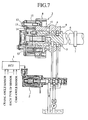
- FIGS 7 and 8 are cross sections showing a conventional valve timing variation device.
- Figures 9A and 9B are cross sections showing the structure of a chip seal of a valve timing variation device.
- reference numeral 1 denotes an electronic control unit (hereafter ECU) which controls the oil control valve 2 and the like.
- 2 is an oil control valve (hereafter OCV) which supplies working oil to the actuator 3 under the control of the ECU 1.
- 3 is an actuator which controls the displacement angle of the camshaft 6 with respect to the timing pulley 8 when the working oil is supplied from the OCV 2 and which continuously regulates the timing of the opening and closing of the air intake valve.
- 4 and 5 are oil passages through which the working oil which is supplied from the OCV 2 flows.
- 6 is a camshaft which drives the opening and closing of the intake valve of the engine.
- 7 is a cam of the camshaft 6.
- 8 is a timing pulley arranged on one end of the camshaft 6.
- 9 is a bearing of the cams
- 10 is a housing mounted so as to be freely rotatable with respect to the camshaft 6.
- 11 is a case fixed to the housing 10.
- 12 is a bolt which fixes the case 11 to the housing 10.
- 13 is a rotor which is fixed to the camshaft 6 and which rotates relative to the case 11.
- 14 and 16 are chip seals which prevent the movement of oil between the oil chambers 18 which are separated by the case 11 and the rotor 13.
- 15 is a metallic blade spring which is disposed between case 11 and the chip seal 14 and which pressures the chip seal 14 against the rotor 13.
- 17 is a metallic blade spring which is disposed between rotor 13 and the chip seal 14 and which pressures the chip seal 16 against the case 11.
- 18 are oil chambers which are separated by the case 11 and the rotor 13.
- valve timing variation device controls the rotational direction of the housing 10 and the timing of the opening and closing of the air intake and exhaust valves of the engine by controlling of the amount of oil flowing into each oil chamber 18, in order to prevent the movement of oil between the oil chambers 18, a chip seal 14 is pushed against the rotor 13 and a chip seal 16 is pushed against the case 11.
- the attachment of the chip seals 14 and 16 is performed by insertion between the case 11 and the rotor 13 in the direction from the left side of Figures 9A and 9B (the front of Figure 8) to the right side (the back of Figure 8) so that the chip seals 14, 16 and the metallic blade springs 15, 17 do not become disassembled.
- JP-A-9-324611 Apart from the conventional example given above, a similar arrangement is disclosed in JP-A-9-324611.
- the present invention is proposed to solve the above problems and has the objective of obtaining a valve timing variation device which can increase assemblying efficiency when the chip seals are assembled.
- the chip seal of the valve timing variation device has the shape of a letter "L" when taken in cross section.
- the cross sectional shape of the chip seal has the shape of a letter "L"
- the efficiency of assembling the chip seal can be increased.
- the valve timing variation device is adapted to integrally form a chip seal and a flexible member.
- the chip seal and the flexible member are formed integrally, assemblying efficiency of the chip seal is conspicuously increased.
- the valve timing variation device is adapted to insert a blade spring into the chip seal.
- the blade spring is formed to be inserted into the chip seal, it is possible to avoid the deficiency of the chip seal and the blade spring disassembling during assembly.
- the valve timing variation device is adapted so that both legs of the chip seal are bent to form a flexible member.
- both legs of the chip seal are bent to form a flexible member, it is possible to reduce manufacturing costs and at the same time conspicuously improve assembling efficiency of the chip seal.
- the valve timing variation device is adapted to fix the flexible member which has lower hardness than the chip seal to the chip seal.
- the flexible member which has lower hardness than the chip seal by fixing the flexible member which has lower hardness than the chip seal to the chip seal, it is possible to lower manufacturing costs and to conspicuously increase assembling efficiency of the chip seal.
- valve timing variation device adapted to construct the member on the rotor side of the chip seal using soft flexible resin.
- using soft flexible resin to construct the member on the rotor side of the chip seal enables the flexible member to be dispensed with.
- the valve timing variation device is adapted so that the chip seal is pushed to the case side by the flexible member.
- the chip seal is pushed to the case side by the flexible member, it is possible to prevent the movement of oil between the oil chambers which are separated by the case and the rotor.
- valve timing variation device is adapted so that the chip seal is pushed to the rotor side by the flexible member.
- the chip seal is pushed to the rotor side by the flexible member, it is possible to prevent the movement of oil between the oil chambers which are separated by the case and the rotor.
- FIGS 1A and 1B are cross sections which show the structure of a chip seal of a valve timing variation device according to the first embodiment of the present invention.
- reference numeral 11 denotes a case fixed to a housing 10
- 11a is a notch of the case 11 which stores the chip seal 21
- 13 is a rotor which fixed to the camshaft 6 and which rotates relative to the case 11.
- 13a is a notch of the rotor 13 which stores the chip seal 23.
- 21 and 23 are chip seals which prevent the movement of oil between the oil chambers 18 which are separated by the case 11 and the rotor 13.
- 21a and 23a are distal sections of the chip seals 21, 23.
- 22 is a metallic blade spring (flexible member) which is disposed between the case 11 and the chip seal 21 and which pressures the chip seal 21 against the rotor 13.
- 24 is a is a metallic blade spring (flexible member) which disposed between the rotor 13 and the chip seal 23 and which pressures the chip seal 23 against the case 11.
- the valve timing variable device controls the axial direction of the housing and the timing of the opening and closing of the exhaust valve and the air intake valve of an engine by controlling the amount of oil entering the oil chambers 18.
- a chip seal 21 is pressed against the rotor 13 and a chip seal 23 is pressed against the case 11.
- the chip seal 21 is pressed against the rotor 13 by the metallic blade spring 22 disposed between the case 11 and the chip seal 21.
- the chip seal 23 as shown in Figure 1B is pressed against the case 11 by the metallic blade spring 22 disposed between the rotor 13 and the chip seal 23.
- chip seals 21, 23 are different from conventional chip seals 14, 16. Their cross sectional shape is in the shape of a letter L and the sealing performance of the lateral sections of the chip seals 21, 23 is improved as the lateral sections of the chip seals 21, 23 are stored in the notches 11a, 13a of the rotor 13 and the case 11.
- the assembly of the chip seal 21, 23 is performed by insertion between the case 11 and the rotor 13 from the left side of Figures 1A and 1B (the front of Figure 8) towards the right side (the rear of Figure 8) so that the chip seals 21, 23 and the metallic blade springs 22, 24 do not become disassembled.
- the insertion of the tip 21a, 23a of the chip seals 21, 23 is easy due to the fact that the tip 21a, 23a of the chip seals 21, 23 is narrow in comparison with conventional chip seals 14, 16. Hence the ease of assembly of the chip seal can be improved.
- the L-shaped cross sectional shape of the chip seal 21, 23 was explained.
- the chip seal may be integrated with a flexible member.
- chip seal and the flexible member are integrated by the insertable form of the metallic blade spring 26, 28 with respect to the chip seal 25, 27.
- both legs of the chip seal may be bent to form a flexible member.
- the legs 29a, 29b, 30a, 30b of the chip seal 29, 30 have the shape as shown in Figure 3 and the legs 29a, 29b, 30a, 30b of the chip seal 29, 30 may be flexible.
- the chip seal was explained as integrated with the flexible member.
- a flexible member of lower hardness than the chip seal may be fixed to the chip seal.
- the chip seal 31a when the chip seal 31a is pushed against the rotor 13, the chip seal 31 on the rotor side 13 is constructed using a hard highly slidable resin such as nylon or carbon.
- the chip seal 31b (flexible member) on the case side 11 is constructed using a soft resin with high flexibility such as rubber or elastomer.
- the chip seal 32a on the case side 11 is constructed using a hard highly slidable resin such as nylon or carbon.
- the chip seal 32b (flexible member) on the rotor side 13 is constructed using a soft resin with high flexibility such as rubber or elastomer.
- the flexible chip seal was explained as having flexibility in the leg sections.
- the slidable surface of the chip seals 29, 30 and the leg sections are laminated and both legs 29a, 29b, 30a, 30b may be constructed using a soft highly flexible resin such as rubber or elastomer. Hence the same effect as embodiment 3 can be achieved.
- the cross sectional shape of the chip seal may be in the shape of a letter L.
Landscapes
- Engineering & Computer Science (AREA)
- Mechanical Engineering (AREA)
- General Engineering & Computer Science (AREA)
- Valve Device For Special Equipments (AREA)
- Valve-Gear Or Valve Arrangements (AREA)
- Sealing Devices (AREA)
Applications Claiming Priority (2)
| Application Number | Priority Date | Filing Date | Title |
|---|---|---|---|
| JP10206722A JP2000038909A (ja) | 1998-07-22 | 1998-07-22 | バルブタイミング可変装置 |
| JP20672298 | 1998-07-22 |
Publications (3)
| Publication Number | Publication Date |
|---|---|
| EP0974738A2 true EP0974738A2 (de) | 2000-01-26 |
| EP0974738A3 EP0974738A3 (de) | 2000-05-10 |
| EP0974738B1 EP0974738B1 (de) | 2004-08-04 |
Family
ID=16528033
Family Applications (1)
| Application Number | Title | Priority Date | Filing Date |
|---|---|---|---|
| EP99100348A Expired - Lifetime EP0974738B1 (de) | 1998-07-22 | 1999-01-14 | Variable Ventilsteuervorrichtung |
Country Status (4)
| Country | Link |
|---|---|
| US (2) | US6173688B1 (de) |
| EP (1) | EP0974738B1 (de) |
| JP (1) | JP2000038909A (de) |
| DE (1) | DE69919089T2 (de) |
Cited By (3)
| Publication number | Priority date | Publication date | Assignee | Title |
|---|---|---|---|---|
| WO2006108494A1 (de) * | 2005-04-15 | 2006-10-19 | Schaeffler Kg | Vorrichtung zur variablen einstellung der steuerzeiten von gaswechselventilen einer brennkraftmaschine |
| EP2568053A1 (de) | 2008-05-12 | 2013-03-13 | Genomic Health, Inc. | Tests zur Vorhersage der Reaktionsfähigkeit von Krebspatienten auf Chemotherapiebehandlungsoptionen |
| EP3333381A1 (de) * | 2016-12-12 | 2018-06-13 | Schwäbische Hüttenwerke Automotive GmbH | Hydraulikvorrichtung mit dichtelement |
Families Citing this family (9)
| Publication number | Priority date | Publication date | Assignee | Title |
|---|---|---|---|---|
| JP2001193421A (ja) * | 1999-10-25 | 2001-07-17 | Mitsubishi Electric Corp | バルブタイミング調整装置 |
| DE19963094B4 (de) * | 1999-12-24 | 2014-08-21 | Schaeffler Technologies Gmbh & Co. Kg | Vorrichtung zum Verändern der Steuerzeiten von Gaswechselventilen einer Brennkraftmaschine, insbesondere hydraulische Nockenwellen-Verstelleinrichtung in Rotationskolbenbauart |
| JP2002180806A (ja) * | 2000-12-13 | 2002-06-26 | Mitsubishi Electric Corp | バルブタイミング調整装置 |
| DE102008000757A1 (de) * | 2008-03-19 | 2009-09-24 | Robert Bosch Gmbh | Vorrichtung zum Verändern der Nockenwellenphasenlage |
| JP5585827B2 (ja) * | 2010-07-08 | 2014-09-10 | アイシン精機株式会社 | 弁開閉時期制御装置 |
| JP5607517B2 (ja) * | 2010-12-07 | 2014-10-15 | 株式会社パイオラックス | シール機構 |
| DE102013219405A1 (de) | 2012-09-28 | 2014-04-03 | Denso Corporation | Ventilzeiteinstellungssteuerungsgerät |
| JP6477078B2 (ja) * | 2015-03-18 | 2019-03-06 | 株式会社デンソー | バルブタイミング調整装置 |
| EP3527781A1 (de) * | 2018-02-14 | 2019-08-21 | Fuelsave GmbH | Drehkolbenmotor und verfahren zum betreiben eines drehkolbenmotors |
Citations (1)
| Publication number | Priority date | Publication date | Assignee | Title |
|---|---|---|---|---|
| JPH09324611A (ja) | 1996-06-05 | 1997-12-16 | Toyota Motor Corp | 内燃機関のバルブタイミング可変機構 |
Family Cites Families (11)
| Publication number | Priority date | Publication date | Assignee | Title |
|---|---|---|---|---|
| GB1454747A (en) * | 1975-01-16 | 1976-11-03 | United Stirling Ab & Co | Sealing device to oppose leakage of fluid between two surfaces subject to relative movement |
| US3990819A (en) | 1975-09-26 | 1976-11-09 | Caterpillar Tractor Co. | Seals for rotary mechanisms |
| US5305721A (en) | 1989-06-29 | 1994-04-26 | Burtis Wilson A | Rotary Wankel type engine |
| WO1995031633A1 (en) * | 1994-05-13 | 1995-11-23 | Nippondenso Co., Ltd. | Vane type rotary phase regulator |
| DE19546934C2 (de) * | 1995-12-15 | 2001-05-31 | Schaeffler Waelzlager Ohg | Druckmittelabdichtung für eine Nockenwellenverstellvorrichtung |
| KR100242589B1 (ko) * | 1996-04-04 | 2000-03-02 | 와다 아끼히로 | 내연기관의 가변밸브 타이밍기구 |
| JP3116858B2 (ja) * | 1996-11-29 | 2000-12-11 | トヨタ自動車株式会社 | 内燃機関のバルブタイミング可変機構 |
| JP3029020B2 (ja) * | 1997-04-25 | 2000-04-04 | 株式会社デンソー | 内燃機関用バルブタイミング調整装置 |
| JP3191730B2 (ja) * | 1997-07-17 | 2001-07-23 | 三菱電機株式会社 | 油圧式バルブタイミング調節装置 |
| DE19834143B4 (de) * | 1998-07-29 | 2014-03-20 | Schaeffler Technologies AG & Co. KG | Vorrichtung zum Verändern der Steuerzeiten von Gaswechselventilen einer Brennkraftmaschine, insbesondere Nockenwellenverstelleinrichtung mit Flügelrad |
| DE19908230A1 (de) | 1999-02-25 | 2000-08-31 | Heidelberger Druckmasch Ag | Vorrichtung zur Überwachung von sicherheitsrelevanten Vorgängen an Maschinen |
-
1998
- 1998-07-22 JP JP10206722A patent/JP2000038909A/ja active Pending
- 1998-12-23 US US09/219,812 patent/US6173688B1/en not_active Expired - Fee Related
-
1999
- 1999-01-14 EP EP99100348A patent/EP0974738B1/de not_active Expired - Lifetime
- 1999-01-14 DE DE69919089T patent/DE69919089T2/de not_active Expired - Fee Related
-
2000
- 2000-09-21 US US09/666,328 patent/US6334415B1/en not_active Expired - Fee Related
Patent Citations (1)
| Publication number | Priority date | Publication date | Assignee | Title |
|---|---|---|---|---|
| JPH09324611A (ja) | 1996-06-05 | 1997-12-16 | Toyota Motor Corp | 内燃機関のバルブタイミング可変機構 |
Cited By (5)
| Publication number | Priority date | Publication date | Assignee | Title |
|---|---|---|---|---|
| WO2006108494A1 (de) * | 2005-04-15 | 2006-10-19 | Schaeffler Kg | Vorrichtung zur variablen einstellung der steuerzeiten von gaswechselventilen einer brennkraftmaschine |
| EP2568053A1 (de) | 2008-05-12 | 2013-03-13 | Genomic Health, Inc. | Tests zur Vorhersage der Reaktionsfähigkeit von Krebspatienten auf Chemotherapiebehandlungsoptionen |
| EP2607497A1 (de) | 2008-05-12 | 2013-06-26 | Genomic Health, Inc. | Tests zur Vorhersage der Reaktionsfähigkeit von Krebspatienten auf Chemotherapiebehandlungsoptionen |
| EP3333381A1 (de) * | 2016-12-12 | 2018-06-13 | Schwäbische Hüttenwerke Automotive GmbH | Hydraulikvorrichtung mit dichtelement |
| US10975699B2 (en) | 2016-12-12 | 2021-04-13 | Schwäbische Hüttenwerke Automotive GmbH | Hydraulic device comprising a sealing element |
Also Published As
| Publication number | Publication date |
|---|---|
| DE69919089T2 (de) | 2005-07-21 |
| DE69919089D1 (de) | 2004-09-09 |
| EP0974738B1 (de) | 2004-08-04 |
| US6173688B1 (en) | 2001-01-16 |
| EP0974738A3 (de) | 2000-05-10 |
| JP2000038909A (ja) | 2000-02-08 |
| US6334415B1 (en) | 2002-01-01 |
Similar Documents
| Publication | Publication Date | Title |
|---|---|---|
| US6173688B1 (en) | Valve timing variation device | |
| US6484678B2 (en) | Valve timing regulation device | |
| EP0799976B1 (de) | Variable Ventilzeitsteuervorrichtung für Brennkraftmaschine | |
| KR101169900B1 (ko) | 내연 기관의 가변 밸브 장치 | |
| KR20000071334A (ko) | 공기 흡입 매니폴드용 저 누설 공기 밸브, 공기 흡입매니폴드용 저 누설 공기 밸브 조립체 및 그 제조 방법과,저 누설 매니폴드 | |
| US7784438B2 (en) | Mounting module of oil control valve for tappet control in cylinder deactivation engine | |
| JP2005121136A (ja) | オイルフローコントロールバルブ | |
| DE112008001522B4 (de) | In der Nockenwelle angebrachter Elektromagnet für einen variablen Nockenverstellmechanismus | |
| US10865666B2 (en) | Check valve for exhausting flow of fluid from a variable cam timing phaser | |
| US20110048350A1 (en) | Variable force solenoid with integrated position sensor | |
| US8887871B2 (en) | Check valve of cylinder head | |
| US20090044770A1 (en) | Camshaft phaser wiper seal with integral spring | |
| US8555841B2 (en) | Coupling plate between valves | |
| JP2012026270A (ja) | Egrバルブ装置および弁軸組み付け方法 | |
| EP3683433A1 (de) | Egr-ventil für fahrzeug | |
| US6119645A (en) | Valve stem seal with non-rotatable retainer | |
| US6427654B2 (en) | Device for changing the control timing of the gas exchange valves of an internal combustion engine, in particular a hydraulic camshaft adjustment device of the rotary piston type | |
| KR101032594B1 (ko) | V형 내연기관의 가변 흡기 장치 | |
| US6904880B2 (en) | VCT sensor and actuator module | |
| EP3121394A1 (de) | Nockenwellenversteller mit einer drehventilspule | |
| EP1703088A1 (de) | Variable Ventilsteuervorrichtung | |
| US20100089349A1 (en) | Valve Timing Adjusting Device | |
| EP3156618A1 (de) | Motor | |
| US6935291B2 (en) | Variable valve timing controller | |
| JPH0861250A (ja) | 歯車ポンプ及び該歯車ポンプをなじみ運転するための方法 |
Legal Events
| Date | Code | Title | Description |
|---|---|---|---|
| PUAI | Public reference made under article 153(3) epc to a published international application that has entered the european phase |
Free format text: ORIGINAL CODE: 0009012 |
|
| AK | Designated contracting states |
Kind code of ref document: A2 Designated state(s): DE FR IT |
|
| AX | Request for extension of the european patent |
Free format text: AL;LT;LV;MK;RO;SI |
|
| PUAL | Search report despatched |
Free format text: ORIGINAL CODE: 0009013 |
|
| AK | Designated contracting states |
Kind code of ref document: A3 Designated state(s): AT BE CH CY DE DK ES FI FR GB GR IE IT LI LU MC NL PT SE |
|
| AX | Request for extension of the european patent |
Free format text: AL;LT;LV;MK;RO;SI |
|
| 17P | Request for examination filed |
Effective date: 20000526 |
|
| AKX | Designation fees paid |
Free format text: DE FR IT |
|
| 17Q | First examination report despatched |
Effective date: 20021204 |
|
| GRAP | Despatch of communication of intention to grant a patent |
Free format text: ORIGINAL CODE: EPIDOSNIGR1 |
|
| GRAS | Grant fee paid |
Free format text: ORIGINAL CODE: EPIDOSNIGR3 |
|
| GRAA | (expected) grant |
Free format text: ORIGINAL CODE: 0009210 |
|
| AK | Designated contracting states |
Kind code of ref document: B1 Designated state(s): DE FR IT |
|
| REF | Corresponds to: |
Ref document number: 69919089 Country of ref document: DE Date of ref document: 20040909 Kind code of ref document: P |
|
| ET | Fr: translation filed | ||
| PLBE | No opposition filed within time limit |
Free format text: ORIGINAL CODE: 0009261 |
|
| STAA | Information on the status of an ep patent application or granted ep patent |
Free format text: STATUS: NO OPPOSITION FILED WITHIN TIME LIMIT |
|
| 26N | No opposition filed |
Effective date: 20050506 |
|
| PGFP | Annual fee paid to national office [announced via postgrant information from national office to epo] |
Ref country code: DE Payment date: 20060123 Year of fee payment: 8 |
|
| PGFP | Annual fee paid to national office [announced via postgrant information from national office to epo] |
Ref country code: FR Payment date: 20060125 Year of fee payment: 8 |
|
| PGFP | Annual fee paid to national office [announced via postgrant information from national office to epo] |
Ref country code: IT Payment date: 20060131 Year of fee payment: 8 |
|
| PG25 | Lapsed in a contracting state [announced via postgrant information from national office to epo] |
Ref country code: DE Free format text: LAPSE BECAUSE OF NON-PAYMENT OF DUE FEES Effective date: 20070801 |
|
| REG | Reference to a national code |
Ref country code: FR Ref legal event code: ST Effective date: 20070930 |
|
| PG25 | Lapsed in a contracting state [announced via postgrant information from national office to epo] |
Ref country code: FR Free format text: LAPSE BECAUSE OF NON-PAYMENT OF DUE FEES Effective date: 20070131 |
|
| PG25 | Lapsed in a contracting state [announced via postgrant information from national office to epo] |
Ref country code: IT Free format text: LAPSE BECAUSE OF NON-PAYMENT OF DUE FEES Effective date: 20070114 |