EP0972444A2 - Vorrichtung zur Oberflächenabsaugung eines Flüssigkeitsspiegels - Google Patents
Vorrichtung zur Oberflächenabsaugung eines Flüssigkeitsspiegels Download PDFInfo
- Publication number
- EP0972444A2 EP0972444A2 EP99112516A EP99112516A EP0972444A2 EP 0972444 A2 EP0972444 A2 EP 0972444A2 EP 99112516 A EP99112516 A EP 99112516A EP 99112516 A EP99112516 A EP 99112516A EP 0972444 A2 EP0972444 A2 EP 0972444A2
- Authority
- EP
- European Patent Office
- Prior art keywords
- float
- receiving part
- swimming
- float housing
- hollow cylinder
- Prior art date
- Legal status (The legal status is an assumption and is not a legal conclusion. Google has not performed a legal analysis and makes no representation as to the accuracy of the status listed.)
- Granted
Links
- XLYOFNOQVPJJNP-UHFFFAOYSA-N water Substances O XLYOFNOQVPJJNP-UHFFFAOYSA-N 0.000 title abstract description 9
- 230000009182 swimming Effects 0.000 claims abstract description 26
- 238000004873 anchoring Methods 0.000 claims abstract description 6
- 239000000853 adhesive Substances 0.000 claims description 13
- 230000001070 adhesive effect Effects 0.000 claims description 13
- 239000007788 liquid Substances 0.000 claims description 5
- 239000002689 soil Substances 0.000 abstract 1
- 238000007789 sealing Methods 0.000 description 4
- 238000009434 installation Methods 0.000 description 3
- 238000007667 floating Methods 0.000 description 2
- 239000002245 particle Substances 0.000 description 2
- 238000004140 cleaning Methods 0.000 description 1
- 238000010276 construction Methods 0.000 description 1
- 238000005516 engineering process Methods 0.000 description 1
- 210000003746 feather Anatomy 0.000 description 1
- 239000012530 fluid Substances 0.000 description 1
- 239000003292 glue Substances 0.000 description 1
- 239000012535 impurity Substances 0.000 description 1
- 239000000463 material Substances 0.000 description 1
- 239000008239 natural water Substances 0.000 description 1
- 239000000758 substrate Substances 0.000 description 1
- 239000002352 surface water Substances 0.000 description 1
Images

Classifications
-
- A—HUMAN NECESSITIES
- A01—AGRICULTURE; FORESTRY; ANIMAL HUSBANDRY; HUNTING; TRAPPING; FISHING
- A01K—ANIMAL HUSBANDRY; AVICULTURE; APICULTURE; PISCICULTURE; FISHING; REARING OR BREEDING ANIMALS, NOT OTHERWISE PROVIDED FOR; NEW BREEDS OF ANIMALS
- A01K63/00—Receptacles for live fish, e.g. aquaria; Terraria
- A01K63/04—Arrangements for treating water specially adapted to receptacles for live fish
Definitions
- the invention relates to a device for surface suction the liquid level of a swimming facility, especially a swimming pond, with a float and a float housing, against which the float is vertically displaceable and into a suction line flows into.
- Known devices of this type are often found as so-called hanging skimmer for surface suction of free-standing, smaller swimming pools their application. This are simply hung on the pool edge and exist in Essentially consisting of a float housing and one Float, which slipped over the float housing and is vertically movable, this due to its great buoyancy of the fluctuations in the pelvic level can adjust.
- the object of the invention is to provide a device the secure attachment with little, technical Effort allows and not disturbing for swimming works.
- the float case can do this without that The presence of a pool edge at the correct height be attached so that the float used the Fluid fluctuations can follow freely and the full Functionality of the skimmer is guaranteed.
- the Fastener can be completely in the bottom substrate of the swimming pond are embedded and therefore results in that Bathers or swimming no disturbing, protruding parts. This also results in a optically attractive design because of the fastener due to its concealed installation in the floor from the outside becomes visible.
- this can Fastener from a the float housing and the Float at least partially surrounding the receiving part be educated.
- the float housing with the Receiving part in a suitable depth of the swimming pond securely fixed and the float inserted become.
- the receiving part can be completely in the ground of the water are embedded and therefore acts for the Bathers or swimming not disturbing, though a relatively small installation depth is required and so at artificial ponds the sealing film at the point of application not much lower below the water level than must be relocated in the other places. Also at relatively low weight of the receiving part is one secure anchoring of the device according to the invention possible.
- the receiving part have at least one adhesive surface with which one corresponding surface of the float housing can be glued.
- the adhesive surface - seen in the position of use - in the area of the lower inside of the receiving part is arranged horizontally.
- the receiving part be designed in the form of a hollow cylinder, the Inner diameter larger than the outer diameter of the Can be a swimmer, but - seen in use - in Area of the bottom of the hollow cylinder an outwards projecting flange-like approach for anchoring in the ground respectively Shore area can be molded.
- the flange-like approach of the hollow cylinder can very well in the surface of a swimming pond made of gravel or gravel embedded and thereby fixed there.
- the hollow cylindrical Shape allows a completely free of disabilities Swimmer's agility.
- a device for surface suction shown in Fig. 3 the liquid level 9 of a swimming facility, in particular a swimming pond 12 is used for cleaning of water from light, floating on the surface Particles such as Leaves, bird feathers etc.
- the surface water is constantly sucked off and filtered.
- the filtered water can do that swimming pond can be fed again.
- the only in Fig. 3 Part of the apparent swimming pool 12 is an artificial one created swimming or garden pond or similar artificial or natural water, but in their place any other type of closed within the scope of the invention swimming pool can be formed. Sealing the Floating system 12 against the subsurface takes place according to FIG. 3 via a sealing film 7.
- a float 5 In order to extract the impurities regardless of Liquid level fluctuations constantly on the surface To be able to perform, a float 5 is provided, the relative to a fixed float housing 4 is movable and always on due to its buoyancy the level of the liquid surface 9 is maintained.
- a suction line 6 opens out at the bottom of the float housing 4 a to a suction pump, not shown in Fig. 3 leads, which in operation constantly water through the suction line 6 sucks.
- interchangeable filter cartridges housed the Retain dirt particles.
- an element for fastening 1 of the float housing 4 in the bottom or bank area of the swimming system 12 provided, the fastener 1 in the bottom or bank 8 of the swimming facility 12 can be anchored.
- this fastener 1 can be anchored in the ground or bank 8.
- the fastener is made from a float housing 4 and the float 5 at least partially surrounding it Receiving part 1 formed.
- This receiving part 1 enables with a relatively low weight a secure anchor, whereby there is also a relatively small installation depth within the Pond bottom results, so that the sealing film 7 is not be laid much deeper than in the other places got to.
- the anchoring can also be applied to various others Species, such as anchor blocks sunk into the ground, e.g. made of concrete, on which the float housing can be fixed.
- Float housings and floats can do this without to further disrupt swimming operations, being due to the complete embedding of the receiving part in the floor despite the device according to the invention optically attractive bank area can be designed.
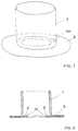
- the receiving part 1 is separated from the Device according to the invention shown. It has one Adhesive surface 2 with which a corresponding surface of the Float housing 4 can be glued, the adhesive surface 2 - Seen in use - in the area of the bottom of the Receiving part 1 is arranged horizontally.
- the receiving part is in the form of a hollow cylinder 1 formed, the inner diameter of which is larger than that Outside diameter of the float 5 is, so this how 3, freely opposite the receiving part 1 is mobile.
- the receiving part in the floor or shore 8 is - seen in the use position - in Area of the underside of the hollow cylinder 1 to the outside molded flange-like approach 3 above.
- the device according to the invention is preferred in this way attached that they are very well covered from the outside is and looks completely inconspicuous.
- the adhesive surface 2 is on one, in the interior of the Hollow cylinder 1 projecting concentric, annular Approach 10 (Fig. 1, 2) formed in the shown Embodiment aligned with the flange-like approach 3 runs.
- the float housing 4 can, for example, with a PVC adhesive on the adhesive surface 2 of the approach 10 be glued with full adhesive power even under water maintains.
Landscapes
- Life Sciences & Earth Sciences (AREA)
- Environmental Sciences (AREA)
- Marine Sciences & Fisheries (AREA)
- Animal Husbandry (AREA)
- Biodiversity & Conservation Biology (AREA)
- Tents Or Canopies (AREA)
- Devices For Medical Bathing And Washing (AREA)
- Hooks, Suction Cups, And Attachment By Adhesive Means (AREA)
- Removal Of Floating Material (AREA)
Abstract
Description
- Fig. 1
- einen Schrägriss eines Teils einer Ausführungsform der Erfindung;
- Fig. 2
- einen Schnitt durch die Darstellung gemäß Fig. 1 und
- Fig. 3
- einen Schnitt durch die Ausführungsform der Erfindung gemäß Fig. 1 in eingebautem Zustand.
Claims (6)
- Vorrichtung zur Oberflächenabsaugung des Flüssigkeitsspiegels einer Schwimmanlage, insbesondere eines Schwimmteichs, mit einem Schwimmer und einem Schwimmer-Gehäuse, gegenüber welchem der Schwimmer vertikal verschiebbar ist und in das eine Saugleitung einmündet,
dadurch gekennzeichnet, dassein Element zur Befestigung (1) des Schwimmer-Gehäuses (4) im Boden- beziehungsweise Uferbereich der Schwimmanlage vorgesehen ist,dieses Befestigungselement (1) im Boden beziehungsweise Ufer (8) der Schwimmanlage (12) verankerbar ist. - Vorrichtung nach Anspruch 1,
dadurch gekennzeichnet, dassdas Befestigungselement aus einem das Schwimmer-Gehäuse (4) und den Schwimmer (5) zumindest teilweise umgebenden Aufnahmeteil (1) gebildet ist. - Vorrichtung nach Anspruch 2,
dadurch gekennzeichnet, dassdas Aufnahmeteil (1) zumindest eine Klebefläche (2) aufweist, mit der eine entsprechende Fläche des Schwimmer-Gehäuses (4) verklebbar ist. - Vorrichtung nach Anspruch 2 oder 3,
dadurch gekennzeichnet, dassdie Klebefläche (2) - in Gebrauchslage gesehen - im Bereich der unteren Innenseite des Aufnahmeteils (1) horizontal verlaufend angeordnet ist. - Vorrichtung nach Anspruch 2, 3 oder 4,
dadurch gekennzeichnet, dassdas Aufnahmeteil in Form eines Hohlzylinders (1) ausgebildet ist, dessen Innendurchmesser größer als der Außendurchmesser des Schwimmers (5) ist, und dass, in Gebrauchslage gesehen,im Bereich der Unterseite des Hohlzylinders (1) ein nach außen vorstehender flanschartiger Ansatz (3) zur Verankerung im Boden- beziehungsweise Uferbereich (8) angeformt ist. - Vorrichtung nach Anspruch 5,
dadurch gekennzeichnet, dassdie Klebefläche (2) auf einem, in den Innenraum des Hohlzylinders (1) ragenden konzentrischen, ringkreisförmigen Ansatz (10) ausgebildet ist, der vorzugsweise fluchtend mit dem flanschartigen Ansatz (3) verläuft.
Priority Applications (2)
| Application Number | Priority Date | Filing Date | Title |
|---|---|---|---|
| AT99112516T ATE276654T1 (de) | 1998-07-13 | 1999-07-01 | Vorrichtung zur oberflächenabsaugung eines flüssigkeitsspiegels |
| SI9930713T SI0972444T1 (en) | 1998-07-13 | 1999-07-01 | Device for surface suction removal of a water surface |
Applications Claiming Priority (3)
| Application Number | Priority Date | Filing Date | Title |
|---|---|---|---|
| AT47098U AT3199U1 (de) | 1998-07-13 | 1998-07-13 | Vorrichtung zur oberflächenabsaugung eines flüssigkeitsspiegels |
| AT47098U | 1998-07-13 | ||
| AT47098 | 1998-07-13 |
Publications (3)
| Publication Number | Publication Date |
|---|---|
| EP0972444A2 true EP0972444A2 (de) | 2000-01-19 |
| EP0972444A3 EP0972444A3 (de) | 2002-10-09 |
| EP0972444B1 EP0972444B1 (de) | 2004-09-22 |
Family
ID=3491476
Family Applications (1)
| Application Number | Title | Priority Date | Filing Date |
|---|---|---|---|
| EP19990112516 Expired - Lifetime EP0972444B1 (de) | 1998-07-13 | 1999-07-01 | Vorrichtung zur Oberflächenabsaugung eines Flüssigkeitsspiegels |
Country Status (4)
| Country | Link |
|---|---|
| EP (1) | EP0972444B1 (de) |
| AT (1) | AT3199U1 (de) |
| DE (1) | DE59910562D1 (de) |
| ES (1) | ES2229588T3 (de) |
Cited By (1)
| Publication number | Priority date | Publication date | Assignee | Title |
|---|---|---|---|---|
| EP2093331A1 (de) * | 2008-02-22 | 2009-08-26 | Minnova Mineralien Handelsges.M.B.H. | Schwimmergehäuse und Vorrichtung zur Oberflächenabsaugung mit einem Schwimmergehäuse |
Families Citing this family (1)
| Publication number | Priority date | Publication date | Assignee | Title |
|---|---|---|---|---|
| CN108849706A (zh) * | 2018-07-10 | 2018-11-23 | 浙江大学 | 用于池塘循环水养殖的全自动高效除污系统 |
Family Cites Families (4)
| Publication number | Priority date | Publication date | Assignee | Title |
|---|---|---|---|---|
| GB348794A (en) * | 1930-03-26 | 1931-05-21 | Albert Cunliffe | Apparatus for treating the water contained by a pool, swimming-bath or the like |
| FR2642104A1 (fr) * | 1989-01-25 | 1990-07-27 | Chandler Michael | Dispositif de regulation de debit pour circuit de nettoyage d'un bassin, en particulier d'une piscine |
| US5133854A (en) * | 1990-07-13 | 1992-07-28 | Tibor Horvath | Skimmer with self-adjusting floating collector |
| US5275721A (en) * | 1993-02-08 | 1994-01-04 | Oommen Mathews | Swimming pool super-skimmer |
-
1998
- 1998-07-13 AT AT47098U patent/AT3199U1/de not_active IP Right Cessation
-
1999
- 1999-07-01 EP EP19990112516 patent/EP0972444B1/de not_active Expired - Lifetime
- 1999-07-01 ES ES99112516T patent/ES2229588T3/es not_active Expired - Lifetime
- 1999-07-01 DE DE59910562T patent/DE59910562D1/de not_active Expired - Lifetime
Non-Patent Citations (1)
| Title |
|---|
| None |
Cited By (1)
| Publication number | Priority date | Publication date | Assignee | Title |
|---|---|---|---|---|
| EP2093331A1 (de) * | 2008-02-22 | 2009-08-26 | Minnova Mineralien Handelsges.M.B.H. | Schwimmergehäuse und Vorrichtung zur Oberflächenabsaugung mit einem Schwimmergehäuse |
Also Published As
| Publication number | Publication date |
|---|---|
| ES2229588T3 (es) | 2005-04-16 |
| EP0972444B1 (de) | 2004-09-22 |
| DE59910562D1 (de) | 2004-10-28 |
| EP0972444A3 (de) | 2002-10-09 |
| AT3199U1 (de) | 1999-11-25 |
Similar Documents
| Publication | Publication Date | Title |
|---|---|---|
| EP0972444B1 (de) | Vorrichtung zur Oberflächenabsaugung eines Flüssigkeitsspiegels | |
| DE2444722A1 (de) | Schwimmbecken aus kunststoff | |
| DE4315535A1 (de) | Kunststoff-Schacht | |
| DE1960511A1 (de) | Vorrichtung zum Reinigen verschmutzten Wassers | |
| WO2011015472A1 (de) | Filtervorrichtung | |
| DE2613826A1 (de) | Vorrichtung zum sammeln und speichern von regenwasser o.dgl. | |
| DE3729353A1 (de) | Einziehbarer mehrzweckpfahl zum beistand bei ausgrabungsarbeiten in archaeologischen gelaenden | |
| DE3509420C2 (de) | ||
| DD270835A3 (de) | Ringkanalartiges grossaquarium | |
| EP2093331B1 (de) | Schwimmergehäuse und Vorrichtung zur Oberflächenabsaugung mit einem Schwimmergehäuse | |
| DE2126562A1 (de) | Schwimmbecken | |
| DE202006011205U1 (de) | Denkmal, insbesondere Grabmal | |
| DE102018001306B4 (de) | Skimmervorrichtung | |
| DE3506745C1 (de) | Künstlicher Teich | |
| DE19825150A1 (de) | Hydraulisch, pneumatisch betriebener Kolbenpumpen-Eiweißabschäumer | |
| DE7914845U1 (de) | Betonbaustein zur abgrenzung von gelaendebereichen | |
| DE29515700U1 (de) | In Stein gefaßte Wasserentnahmestelle für den Freiraum | |
| DE102016121908B4 (de) | Energiespeichernde, hydraulische Vorrichtung | |
| DE202018000866U1 (de) | Skimmervorrichtung | |
| DE212010000192U1 (de) | Ein freistehender Fischteich | |
| DE102004055772B4 (de) | Vorrichtung und Verfahren zu ihrer Herstellung sowie ihre Verwendung zur Abdeckung und/oder zum Überdecken von Gegenständen in Haus und Garten | |
| DD152955A1 (de) | Verfahren zur lokalen minderung der wind-und stroemungsbedingten schwebstoffanreicherung in stehenden und langsam durchflossenen gewaessern | |
| DE7100882U (de) | Schwimmbecken | |
| DE1985012U (de) | Filter-pumpenanlage zum reinigen von fluessigkeitsbehaeltern, insbesondere badebecken. | |
| DE102011018728A9 (de) | Vorrichtung und Anordnung zur Aufnahme von Wasser bei Überschwemmungen |
Legal Events
| Date | Code | Title | Description |
|---|---|---|---|
| PUAI | Public reference made under article 153(3) epc to a published international application that has entered the european phase |
Free format text: ORIGINAL CODE: 0009012 |
|
| AK | Designated contracting states |
Kind code of ref document: A2 Designated state(s): AT BE CH CY DE DK ES FI FR GB GR IE IT LI LU MC NL PT SE |
|
| AX | Request for extension of the european patent |
Free format text: AL;LT;LV;MK;RO;SI |
|
| RTI1 | Title (correction) |
Free format text: DEVICE FOR SURFACE SUCTION REMOVAL OF A WATER SURFACE |
|
| PUAL | Search report despatched |
Free format text: ORIGINAL CODE: 0009013 |
|
| AK | Designated contracting states |
Kind code of ref document: A3 Designated state(s): AT BE CH CY DE DK ES FI FR GB GR IE IT LI LU MC NL PT SE |
|
| AX | Request for extension of the european patent |
Free format text: AL;LT;LV;MK;RO;SI |
|
| 17P | Request for examination filed |
Effective date: 20030228 |
|
| AKX | Designation fees paid |
Designated state(s): AT BE CH CY DE DK ES FI FR GB GR IE IT LI LU MC NL PT SE |
|
| AXX | Extension fees paid |
Extension state: SI Payment date: 20030228 |
|
| 17Q | First examination report despatched |
Effective date: 20030901 |
|
| GRAP | Despatch of communication of intention to grant a patent |
Free format text: ORIGINAL CODE: EPIDOSNIGR1 |
|
| GRAS | Grant fee paid |
Free format text: ORIGINAL CODE: EPIDOSNIGR3 |
|
| GRAA | (expected) grant |
Free format text: ORIGINAL CODE: 0009210 |
|
| AK | Designated contracting states |
Kind code of ref document: B1 Designated state(s): AT BE CH CY DE DK ES FI FR GB GR IE IT LI LU MC NL PT SE |
|
| AX | Request for extension of the european patent |
Extension state: SI |
|
| PG25 | Lapsed in a contracting state [announced via postgrant information from national office to epo] |
Ref country code: IE Free format text: LAPSE BECAUSE OF FAILURE TO SUBMIT A TRANSLATION OF THE DESCRIPTION OR TO PAY THE FEE WITHIN THE PRESCRIBED TIME-LIMIT Effective date: 20040922 Ref country code: GB Free format text: LAPSE BECAUSE OF FAILURE TO SUBMIT A TRANSLATION OF THE DESCRIPTION OR TO PAY THE FEE WITHIN THE PRESCRIBED TIME-LIMIT Effective date: 20040922 Ref country code: FI Free format text: LAPSE BECAUSE OF FAILURE TO SUBMIT A TRANSLATION OF THE DESCRIPTION OR TO PAY THE FEE WITHIN THE PRESCRIBED TIME-LIMIT Effective date: 20040922 |
|
| REG | Reference to a national code |
Ref country code: GB Ref legal event code: FG4D Free format text: NOT ENGLISH |
|
| REG | Reference to a national code |
Ref country code: CH Ref legal event code: EP |
|
| REG | Reference to a national code |
Ref country code: IE Ref legal event code: FG4D Free format text: GERMAN |
|
| REF | Corresponds to: |
Ref document number: 59910562 Country of ref document: DE Date of ref document: 20041028 Kind code of ref document: P |
|
| REG | Reference to a national code |
Ref country code: CH Ref legal event code: NV Representative=s name: ISLER & PEDRAZZINI AG |
|
| PG25 | Lapsed in a contracting state [announced via postgrant information from national office to epo] |
Ref country code: SE Free format text: LAPSE BECAUSE OF FAILURE TO SUBMIT A TRANSLATION OF THE DESCRIPTION OR TO PAY THE FEE WITHIN THE PRESCRIBED TIME-LIMIT Effective date: 20041222 Ref country code: DK Free format text: LAPSE BECAUSE OF FAILURE TO SUBMIT A TRANSLATION OF THE DESCRIPTION OR TO PAY THE FEE WITHIN THE PRESCRIBED TIME-LIMIT Effective date: 20041222 |
|
| REG | Reference to a national code |
Ref country code: GR Ref legal event code: EP Ref document number: 20040404194 Country of ref document: GR |
|
| REG | Reference to a national code |
Ref country code: PT Ref legal event code: SC4A Effective date: 20041123 |
|
| REG | Reference to a national code |
Ref country code: ES Ref legal event code: FG2A Ref document number: 2229588 Country of ref document: ES Kind code of ref document: T3 |
|
| GBV | Gb: ep patent (uk) treated as always having been void in accordance with gb section 77(7)/1977 [no translation filed] |
Effective date: 20040922 |
|
| REG | Reference to a national code |
Ref country code: IE Ref legal event code: FD4D |
|
| PG25 | Lapsed in a contracting state [announced via postgrant information from national office to epo] |
Ref country code: CY Free format text: LAPSE BECAUSE OF FAILURE TO SUBMIT A TRANSLATION OF THE DESCRIPTION OR TO PAY THE FEE WITHIN THE PRESCRIBED TIME-LIMIT Effective date: 20050701 |
|
| ET | Fr: translation filed | ||
| PLBE | No opposition filed within time limit |
Free format text: ORIGINAL CODE: 0009261 |
|
| STAA | Information on the status of an ep patent application or granted ep patent |
Free format text: STATUS: NO OPPOSITION FILED WITHIN TIME LIMIT |
|
| PG25 | Lapsed in a contracting state [announced via postgrant information from national office to epo] |
Ref country code: MC Free format text: LAPSE BECAUSE OF NON-PAYMENT OF DUE FEES Effective date: 20050731 |
|
| 26N | No opposition filed |
Effective date: 20050623 |
|
| REG | Reference to a national code |
Ref country code: CH Ref legal event code: PCAR Free format text: ISLER & PEDRAZZINI AG;POSTFACH 1772;8027 ZUERICH (CH) |
|
| PGFP | Annual fee paid to national office [announced via postgrant information from national office to epo] |
Ref country code: PT Payment date: 20090623 Year of fee payment: 11 |
|
| PGFP | Annual fee paid to national office [announced via postgrant information from national office to epo] |
Ref country code: GR Payment date: 20090728 Year of fee payment: 11 |
|
| PGFP | Annual fee paid to national office [announced via postgrant information from national office to epo] |
Ref country code: ES Payment date: 20100726 Year of fee payment: 12 |
|
| REG | Reference to a national code |
Ref country code: PT Ref legal event code: MM4A Free format text: LAPSE DUE TO NON-PAYMENT OF FEES Effective date: 20110103 |
|
| REG | Reference to a national code |
Ref country code: SI Ref legal event code: KO00 Effective date: 20110203 |
|
| PG25 | Lapsed in a contracting state [announced via postgrant information from national office to epo] |
Ref country code: PT Free format text: LAPSE BECAUSE OF NON-PAYMENT OF DUE FEES Effective date: 20110103 |
|
| PG25 | Lapsed in a contracting state [announced via postgrant information from national office to epo] |
Ref country code: GR Free format text: LAPSE BECAUSE OF NON-PAYMENT OF DUE FEES Effective date: 20110202 |
|
| REG | Reference to a national code |
Ref country code: CH Ref legal event code: PUE Owner name: AQUAVIVA GMBH Free format text: MINNOVA MINERALIEN-HANDELSGESELLSCHAFT M.B.H.#ULMGASSE 12#8501 LIEBOCH (AT) -TRANSFER TO- AQUAVIVA GMBH#AISTHOFEN 25#4320 PERG (AT) |
|
| PGFP | Annual fee paid to national office [announced via postgrant information from national office to epo] |
Ref country code: LU Payment date: 20130725 Year of fee payment: 15 |
|
| REG | Reference to a national code |
Ref country code: ES Ref legal event code: FD2A Effective date: 20131029 |
|
| PG25 | Lapsed in a contracting state [announced via postgrant information from national office to epo] |
Ref country code: ES Free format text: LAPSE BECAUSE OF NON-PAYMENT OF DUE FEES Effective date: 20110702 |
|
| PGFP | Annual fee paid to national office [announced via postgrant information from national office to epo] |
Ref country code: NL Payment date: 20130722 Year of fee payment: 15 Ref country code: BE Payment date: 20130722 Year of fee payment: 15 |
|
| PGFP | Annual fee paid to national office [announced via postgrant information from national office to epo] |
Ref country code: FR Payment date: 20130719 Year of fee payment: 15 |
|
| PGFP | Annual fee paid to national office [announced via postgrant information from national office to epo] |
Ref country code: IT Payment date: 20130729 Year of fee payment: 15 |
|
| PGFP | Annual fee paid to national office [announced via postgrant information from national office to epo] |
Ref country code: DE Payment date: 20131218 Year of fee payment: 15 |
|
| REG | Reference to a national code |
Ref country code: DE Ref legal event code: R082 Ref document number: 59910562 Country of ref document: DE |
|
| PGFP | Annual fee paid to national office [announced via postgrant information from national office to epo] |
Ref country code: CH Payment date: 20140722 Year of fee payment: 16 |
|
| PGFP | Annual fee paid to national office [announced via postgrant information from national office to epo] |
Ref country code: AT Payment date: 20140606 Year of fee payment: 16 |
|
| REG | Reference to a national code |
Ref country code: DE Ref legal event code: R119 Ref document number: 59910562 Country of ref document: DE |
|
| REG | Reference to a national code |
Ref country code: NL Ref legal event code: V1 Effective date: 20150201 |
|
| PG25 | Lapsed in a contracting state [announced via postgrant information from national office to epo] |
Ref country code: LU Free format text: LAPSE BECAUSE OF NON-PAYMENT OF DUE FEES Effective date: 20140701 |
|
| PG25 | Lapsed in a contracting state [announced via postgrant information from national office to epo] |
Ref country code: NL Free format text: LAPSE BECAUSE OF NON-PAYMENT OF DUE FEES Effective date: 20150201 |
|
| REG | Reference to a national code |
Ref country code: FR Ref legal event code: ST Effective date: 20150331 |
|
| PG25 | Lapsed in a contracting state [announced via postgrant information from national office to epo] |
Ref country code: DE Free format text: LAPSE BECAUSE OF NON-PAYMENT OF DUE FEES Effective date: 20150203 Ref country code: IT Free format text: LAPSE BECAUSE OF NON-PAYMENT OF DUE FEES Effective date: 20140701 |
|
| REG | Reference to a national code |
Ref country code: DE Ref legal event code: R119 Ref document number: 59910562 Country of ref document: DE Effective date: 20150203 |
|
| PG25 | Lapsed in a contracting state [announced via postgrant information from national office to epo] |
Ref country code: FR Free format text: LAPSE BECAUSE OF NON-PAYMENT OF DUE FEES Effective date: 20140731 |
|
| REG | Reference to a national code |
Ref country code: CH Ref legal event code: PL |
|
| REG | Reference to a national code |
Ref country code: GR Ref legal event code: ML Ref document number: 20040404194 Country of ref document: GR Effective date: 20110202 |
|
| REG | Reference to a national code |
Ref country code: AT Ref legal event code: MM01 Ref document number: 276654 Country of ref document: AT Kind code of ref document: T Effective date: 20150701 |
|
| PG25 | Lapsed in a contracting state [announced via postgrant information from national office to epo] |
Ref country code: CH Free format text: LAPSE BECAUSE OF NON-PAYMENT OF DUE FEES Effective date: 20150731 Ref country code: LI Free format text: LAPSE BECAUSE OF NON-PAYMENT OF DUE FEES Effective date: 20150731 |
|
| PG25 | Lapsed in a contracting state [announced via postgrant information from national office to epo] |
Ref country code: AT Free format text: LAPSE BECAUSE OF NON-PAYMENT OF DUE FEES Effective date: 20150701 |
|
| PG25 | Lapsed in a contracting state [announced via postgrant information from national office to epo] |
Ref country code: BE Free format text: LAPSE BECAUSE OF NON-PAYMENT OF DUE FEES Effective date: 20140731 |