EP0971504A2 - Méthode et système de synchronisation ainsi que support d'enrégistrement - Google Patents
Méthode et système de synchronisation ainsi que support d'enrégistrement Download PDFInfo
- Publication number
- EP0971504A2 EP0971504A2 EP99112949A EP99112949A EP0971504A2 EP 0971504 A2 EP0971504 A2 EP 0971504A2 EP 99112949 A EP99112949 A EP 99112949A EP 99112949 A EP99112949 A EP 99112949A EP 0971504 A2 EP0971504 A2 EP 0971504A2
- Authority
- EP
- European Patent Office
- Prior art keywords
- signal
- timing
- information data
- transmission information
- generator
- Prior art date
- Legal status (The legal status is an assumption and is not a legal conclusion. Google has not performed a legal analysis and makes no representation as to the accuracy of the status listed.)
- Withdrawn
Links
Images
Classifications
-
- H—ELECTRICITY
- H04—ELECTRIC COMMUNICATION TECHNIQUE
- H04L—TRANSMISSION OF DIGITAL INFORMATION, e.g. TELEGRAPHIC COMMUNICATION
- H04L7/00—Arrangements for synchronising receiver with transmitter
-
- H—ELECTRICITY
- H04—ELECTRIC COMMUNICATION TECHNIQUE
- H04J—MULTIPLEX COMMUNICATION
- H04J3/00—Time-division multiplex systems
- H04J3/02—Details
- H04J3/06—Synchronising arrangements
- H04J3/0602—Systems characterised by the synchronising information used
- H04J3/0605—Special codes used as synchronising signal
- H04J3/0611—PN codes
Definitions
- the present invention generally relates to a synchronization system, a synchronization method, and a recording medium, and more particularly, to a synchronization system and a synchronization method which realize strict commercial time synchronization by advancing the timing of generation of a PN (Pseudo-random Noise) signal in a upstream station by a transmission line delay.
- PN Pulseudo-random Noise
- An exchange and a first radio station are connected to each other through a first transmission line.
- the aforementioned exchange and a second radio station are connected to each other through a second transmission line.
- 1.5-megabits-per-second (Mbps) high-speed digital commercial transmission lines are used as the aforementioned first and second transmission lines.
- a master station of a time synchronization system is the exchange. Time in (or operating timing of) each of the aforementioned first and second radio stations is controlled by the aforesaid exchange.
- Transmission information data is transmitted by being divided into frames.
- the frame length of frames is set at, for instance, 20 milliseconds (msec).
- time synchronization is realized by time synchronization bits (or frame synchronization bits) periodically sent from the aforementioned exchange to the aforesaid first and second transmission lines.
- the aforementioned exchange is operative to send a frame synchronization bit every frame period.
- the aforesaid first and second radio stations are operative to establish frame synchronization by detecting frame synchronization bits sent from the aforementioned exchange, and to extract transmission information data. Further, the aforementioned first and second radio stations are adapted to operate by employing a signal indicating the timing of detection of a frame synchronization bit as a master timing signal.
- the operation timing of a upstream station differs from that of a downstream station by a transmission line delay.
- the transmission line delay is several msec or so.
- commercial synchronization can be realized with such a degree of accuracy that this transmission line delay is allowed.
- the operation timing of a upstream station differs from that of a downstream station by a transmission line delay. Consequently, the conventional commercial synchronization method has a drawback in that commercial synchronization cannot be realized with accuracy higher than that achieved by allowing the transmission line delay.
- an object of the present invention is to realize strict commercial time synchronization with such a degree of accuracy that a transmission delay comparable to the transmission rate of a transmission line is allowed.
- a synchronization system for synchronizing first and second devices.
- the aforesaid first device comprises first PN signal generating means for generating a PN signal in synchronization with a predetermined timing signal, first multiplexing means for transmitting a multiplexing signal obtained by multiplexing transmission information data to be transmitted and the aforesaid PN signal, first demultiplexing means for receiving a signal transmitted from the aforesaid second device and for demultiplexing the received signal into the transmission information data and the PN signal, and first detection means for detecting a first timing error that is an error between the aforesaid PN signal, which is obtained by demultiplexing by the aforesaid first demultiplexing means, and the aforesaid PN signal generated by the aforesaid first PN signal generating means.
- the aforesaid second device comprises second PN signal generating means for generating a PN signal in synchronization with a predetermined timing signal, second multiplexing means for transmitting a multiplexing signal obtained by multiplexing transmission information data to be transmitted and the aforesaid PN signal, second demultiplexing means for receiving a signal transmitted from the aforesaid first device and for demultiplexing the received signal into the transmission information data arid the PN signal, and second detection means for detecting a first timing error that is an error between the aforesaid PN signal, which is obtained by demultiplexing by the aforesaid second demultiplexing means, and the aforesaid PN signal generated by the aforesaid second PN signal generating means.
- the aforesaid first PN signal generating means shifts operation timing thereof by a time corresponding to half the first timing error detected by the aforesaid first detection means.
- the aforesaid second PN signal generating means corrects operation timing thereof in such a way as to eliminate the aforesaid second timing error detected by the aforesaid second detection means.
- the aforesaid first device further comprises first timing signal generating moans for generating a predetermined timing signal.
- the aforesaid second device further comprises second timing signal generating means.
- the aforesaid first PN signal generating means determines an operation timing thereof in synchronization with a timing signal generated by the aforesaid first timing signal generating means.
- the aforesaid second PN signal generating means determines operation timing thereof in synchronization with a timing signal generated by the aforesaid second timing signal generating means.
- the aforesaid first multiplexing means transmits arbitrary N bits data, which are represented by a PN signal generated by the aforesaid first PN signal generating means, when transmission information data to be transmitted is not present.
- the aforesaid second multiplexing means transmits arbitrary N bits data, which are represented by a PN signal generated by the aforesaid second PN signal generating means, when there is no transmission information data to be transmitted.
- the aforesaid first and second multiplexing means transmit predetermined discrimination information immediately before a PN signal is transmitted.
- the aforesaid first and second demultiplexing means regard signals transmitted immediately after the aforesaid discrimination information as PN signals.
- the aforesaid first detection means detects the aforesaid first timing error by searching a pattern of one period of a PN signal, which is generated by the aforesaid first PN signal generating means, for a consecutive N-bit pattern matching an N-bit pattern represented by a PN signal obtained by demultiplexing by the aforesaid first demultiplying means.
- the aforesaid second detection means detects the aforesaid second timing error by searching a pattern of one period of a PN signal, which is generated by the aforesaid second PN signal generating means, for a consecutive N-bit pattern matching an N-bit pattern represented by a PN signal obtained by demultiplexing by the aforesaid second demultiplexing means.
- timing control is performed so that a pattern represented by a PN signal, which is generated by the aforesaid first PN signal generating means of said first device at a time point (t - ⁇ ) where ⁇ designates a time period during which transmission information data is transmitted from the aforesaid first device to the aforesaid second device, and t denotes a current time point, matches a pattern represented by a PN signal, which is generated by the aforesaid second PN signal generating means of the aforesaid second device at the point in time t.
- a synchronization method having a first process to be performed in a first device and a second process to be performed in a second device, for synchronizing the aforesaid first and second devices.
- the aforesaid first process comprises a first PN signal generating step of generating a PN signal in synchronization with a predetermined timing signal, a first multiplexing step of transmitting a multiplexing signal obtained by multiplexing transmission information data to be transmitted and the aforesaid PN signal, a first demultiplexing step of receiving a signal transmitted from the aforesaid second device and demultiplexing the received signal into transmission information data and a PN signal, and a first detection step of detecting a first timing error that is an error between said PN signal, which is obtained by demultiplexing at the aforesaid first demultiplexing step, and the aforesaid PN signal generated at the aforesaid first PN signal
- the aforesaid second process comprises a second PN signal generating step of generating a PN signal in synchronization with a predetermined timing signal, a second multiplexing step of transmitting a multiplexing signal obtained by multiplexing transmission information data to be transmitted and the aforesaid PN signal, a second demultiplexing step of receiving a signal transmitted from the aforesaid first device and demultiplexing the received signal into transmission information data and a PN signal, and a second detection step of detecting a second timing error that is an error between the aforesaid PN signal, which is obtained by demultiplexing at the aforesaid second demultiplexing step, and the aforesaid PN signal generated at the aforesaid second PN signal generating step.
- PN-signal generation timing is corrected in such a manner as to eliminate the aforesaid second timing error detected at the aforesaid second detection step.
- PN-signal generation timing is shifted ahead by a time period corresponding to half the first timing error detected at the aforesaid first detection step.
- a recording medium on which a program having a first process to be performed in a first device and a second process to be performed in a second device is recorded for synchronizing said first and second devices.
- the aforesaid first process comprises a first PN signal generating step of generating a PN signal in synchronization with a predetermined timing signal, a first multiplexing step of transmitting a multiplexing signal obtained by multiplexing transmission information data to be transmitted and the aforesaid PN signal, a first demultiplexing step of receiving a signal transmitted from the aforesaid second device and demultiplexing the received signal into transmission information data and a PN signal, and a first detection step of detecting a first timing error that is an error between the aforesaid PN signal, which is obtained by demultiplexing at the aforesaid first demultiplexing step, and the aforesaid PN signal generated at the aforesaid first PN signal generating step.
- the aforesaid second process comprises a second PN signal generating step of generating a PN signal in synchronization with a predetermined timing signal, a second multiplexing step of transmitting a multiplexing signal obtained by multiplexing transmission information data to be transmitted and the aforesaid PN signal, a second demultiplexing step of receiving a signal transmitted from the aforesaid first device and demultiplexing the received signal into transmission information data and a PN signal, and a second detection step of detecting a second timing error that is an error between the aforesaid PN signal, which is obtained by demultiplexing at the aforesaid second demultiplexing step, and the aforesaid PN signal generated at the aforesaid second PN signal generating step.
- PN-signal generation timing is corrected in such a manner as to eliminate the aforesaid second timing error detected at the aforesaid second detection step.
- PN-signal generation timing is shifted ahead by a time period corresponding to half the first timing error detected at the aforesaid first detection step.
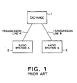
- Figs. 1 and 2 illustrate a system commonly used as a conventional commercial synchronization system. As illustrated in Fig. 1, an exchange 1 and a radio station A2 are connected to each other through a transmission line A. Further, the exchange 1 and a radio station B3 are connected to each other through a transmission line B.
- 1.5 Mbps high-speed digital commercial transmission lines are used as the transmission lines A and B.
- a master station of a time synchronization system is the exchange 1. Time in (or operating timing of) each of the radio stations A and B is controlled by the exchange 1.
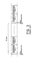
- Fig. 2 shows a format of transmission information data to be transmitted through the transmission lines A and B.
- transmission information data is transmitted by being divided into frames.
- the frame length of frames is set at, for instance, 20 msec.
- time synchronization is realized by time synchronization bits (or frame synchronization bits) periodically sent from the exchange 1 to the transmission lines A and B.
- the exchange 1 is operative to send a frame synchronization bit every frame period.
- the radio stations A and B are operative to establish frame synchronization by detecting frame synchronization bits sent from the exchange 1, and to extract transmission information data, Further, the radio stations A and B are adapted to operate by employing a signal indicating the timing of detection of a frame synchronization bit as a master timing signal.
- the operation timing of a upstream station differs from that of a downstream station by a transmission line delay.
- the transmission line delay is several msec or so.
- commercial synchronization can be realized with such a degree of accuracy that such a transmission line delay is allowed.
- the commercial synchronization system of the present invention is created so as to realize strict commercial time synchronization in comparison with the commercial time synchronization achieved according to the aforementioned conventional method, As will be described later, time synchronization accuracy of the system of the present invention is such that a transmission delay comparable to the transmission rate of an commercial transmission line is allowed.
- the rate of the transmission line is 1.5 Mbps
- this transmission delay is 0.7 microseconds (namely, a time corresponding to one bit of 1.5 Megabits) or so.
- PN sequence therefor has been well known.
- M-sequence namely, a Maximal-length (shift-register) sequence
- quadratic residue sequence namely, a quadratic residue sequence
- twin prime (number) sequence have been known as the PN sequence.
- each PN generator comprises shift registers of stages of the number (N) of the PN sequence and adders (more precisely, exclusive-OR circuits).
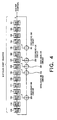
- each of the PN generators is configured as illustrated in, for example, Fig. 4.
- each of the PN generators consists of shift registers of 15 stages 101 to 115 and exclusive-OR circuits 201 to 205.
- each of these PN generators repeatedly outputs a pseudo-random code of the same pattern every period of 32767 bits.
- each of the PN generators a sequence consisting of arbitrary N bits data appears only once in one period of a PN sequence.
- N bits data of the output sequence are known, the operation timing of each of the PN generators can be specified.
- the operation timing of the PN generator placed at the transmitting side can be known by analyzing the N bits data at a receiving side.
- a PN sequence consisting of (32767) bits of one period is preliminarily prepared. Subsequently, shifts between a sequence consisting of N bits data (namely, 15 bits in the case of this example) to be checked and the PN sequence are sequentially found by performing pattern matching therebetween.
- N bits data namely, 15 bits in the case of this example
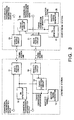
- FIG. 3 is a block diagram illustrating the configuration of the embodiment of an commercial time synchronization system of the present invention.
- a multiplexing circuit 11 of a upstream station is operative to send a downstream station a transmission information data sequence including commercial transmission information data and a PN signal sequence.
- a PN generator 12 is operative to generate a PN signal and to supply the PN signal to the multiplexing circuit 11.
- a master timing generator 15 is operative to generate a master timing signal.
- a demultiplexing circuit 13 demultiplexes the transmission information data sequence sent from the downstream station into the transmission information data and the PN signal sequence.
- a timing detection circuit 14 is operative to detect the timing error between the PN signal sequence supplied from the multiplexing circuit 13 and that generated by the PN generator 12, and to generate timing correction information corresponding to the timing error detected as a result.
- the timing detection circuit 14 is operative to supply this timing correction information to the PN generator 12 and the master timing generator 15.
- the PN generator 12 is operative to correct the operation timing based on the timing correction information supplied from the timing detection circuit 14.
- the master timing generator 15 is operative to correct the master timing based on the timing correction information supplied from the timing detection circuit 14.
- a multiplexing circuit 21 of the downstream station is operative to send the upstream station a transmission information data sequence including commercial transmission information data and a PN signal sequence.
- a PN generator 22 is operative to generate a PN signal and to supply the PN signal to the multiplexing circuit 21.
- a master timing generator 25 is operative to generate a master timing signal.
- a demultiplexing circuit 23 demultiplexes the transmission information data sequence sent from the upstream station into the transmission information data and the PN signal sequence.
- a timing detection circuit 24 is operative to detect the timing error between the PN signal sequence supplied from the multiplexing circuit 23 and that generated by the PN generator 22, and to generate timing correction information so as to eliminate the detected timing error.
- the timing detection circuit 24 is operative to supply this timing correction information to the PN generator 22 and the master timing generator 25.
- the PN generator 22 is operative to correct the operation timing based on the timing correction information supplied from the timing detection circuit 24.
- the master timing generator 25 is operative to correct the master timing based on the timing correction information supplied from the timing detection circuit 24.
- the master timing generator 15 is operative to generate a master timing signal for the entire system.
- the master timing signal is supplied to the PN generator 12.
- the operation timing of the PN generator is determined according to this master timing signal.
- the time when the contents of all shift registers of the PN generator 12 are 1 is determined to be "time 0".
- the multiplexing circuit 11 is operative to determine whether or not transmission information data to be transmitted from the upstream station to the downstream station is present. If the multiplexing circuit 11 determines that transmission information data to be transmitted from the upstream station to the downstream station is present, the transmission information data is transmitted to the downstream station. Conversely, if the multiplexing circuit 11 determines that no transmission information data to be transmitted from the upstream station to the downstream station is present, a PN signal supplied from the PN generator 12 is transmitted to the downstream station. At that time, the system should be adapted so that the PN signal can be separated from transmission information data in the downstream station.
- the system is adapted so that when a PN signal is sent, a specific information word (namely, a unique word) is sent prior to the PN signal.
- a specific information word namely, a unique word
- the multiplexing circuit is prevented from making an erroneous decision. Consequently, in the downstream station, it is decided that a signal sent thereto, subsequent to the unique word, is a PN signal.
- N the number of stages of the PN generator 12
- N-bit PN signal should be sent.
- a transmission information data sequence (including transmission information data and information represented by a PN signal) sent from the upstream station is demultiplexed by the demultiplexing circuit 23 into commercial transmission information data and the PN signal. Then, the PN signal is supplied to the timing detection circuit 24, whereupon timing information on the PN signal is detected.
- the timing error between the PN signal generated by the intraoffice PN generator 22 (namely, the PN generator 22 provided in the downstream station) and the PN signal received from the upstream station is detected.
- the timing detection circuit 24 generates timing correction information to eliminate this timing error and supplies this timing correction information to the PN generator 22 and the master timing generator 25.
- the PN generator 22 corrects the operation timing thereof, based on this timing correction information.
- the master timing generator 25 corrects the master timing according to this timing correction information.
- the PN signal outputted from the lower-rank PN generator 22 is transmitted to the upstream station through the multiplexing circuit 21.
- the multiplexing circuit 21 of the downstream station performs an operation similar to that of the multiplexing circuit 11 of the upstream station. Namely, the multiplexing circuit 21 of the downstream station determines whether or not transmission information data to be transmitted from the downstream station to the upstream station is present. If it is decided that transmission information data to be transmitted is present, the transmission information data is transmitted to the upstream station. If it is decided that no transmission information data to be transmitted is present, the multiplexing circuit 21 of the downstream station transmits a PN signal generated by the PN generator 22 to the upstream station.
- the transmission information data sequence transmitted from the downstream station and received by the upstream station is demultiplexed by the demultiplexing circuit 13 into transmission information data and a PN signal.
- This PN signal is supplied to the timing detection circuit 14, whereupon timing information on this PN signal is detected.
- the timing detection circuit 14 detects the timing error between the PN signal generated by the intraoffice PN generator 12 (namely, the PN generator 12 provided in the higher-tank office) and the PN signal received from the downstream station. This is similar to the operation of the circuit 24 of the downstream station.
- the detection of the timing error in the upstream station necessarily involves the measurement of the transmission line delay caused during the reciprocating transmission of the transmission information data and/or the PN signal between the upstream station and the downstream station.
- the upstream station receives a PN signal from the downstream station by delaying an output of the PN generator 12 of the upstream station by a time 2 ⁇ .
- the operation timing of the PN generator 12 of the upstream station is changed by a time ( ⁇ ) corresponding to half the timing error.
- the PN generator 12 shifts ahead the PN-signal generation timing by the time ⁇ (that is, shifts the phase of the PN signal by an amount corresponding to time ⁇ ).
- the operation timing of the PN generator 12 operates by correcting the operation timing thereof so that the contents of each of the shift registers thereof are 1 at the time point "- ⁇ " (that is, the time ⁇ before the current time point).
- the PN signal whose operation timing has been corrected, is transmitted to the downstream station again.
- the operation timing of the PN generator 22 and the master timing signal generated by the master timing generator 25 are changed according to the received PN signal.
- the time synchronization accuracy of the system of the present invention is such that a transmission delay comparable to the transmission rate (about 0.7 microseconds (namely, a time corresponding to one bit of 1.5 Megabits)) of the transmission line is allowed.
- time synchronization is achieved by using a signal (which represents, for example, a control message exchanged by utilizing the commercial transmission information data) corresponding to a higher layer. Therefore, the description of such time synchronization is omitted herein.
- the number (N) of stages of the PN Sequence may have various values. Thus, as the occasion demands, a suitable number (N) of stages may be selected.
- a time synchronization system using a signal corresponding to a higher layer should be suitably designed in the case of a long period. Further, a strict time synchronization system using a PN signal should be suitably designed.
- Such systems can be applied to both of the cases of employing STM (Synchronous Transfer Mode) and ATM (Asynchronous Transfer Mode) systems as transmission systems.
- STM Serial Transfer Mode
- ATM Asynchronous Transfer Mode
- a PN signal is superimposed on a vacant slot.
- a PN signal is superimposed on a vacant cell.
- the PN generator is constituted by 15 stages of shift registers.
- the number of stages according to the present invention is not limited to 15.
- an M-sequence is used as a PN sequence.
- a square residue sequence or a twin prime sequence may be used as the PN sequence.
- the transmission rate of the transmission line is set at 1.5 Mbps.
- the transmission rate of the transmission line is not limited to 1.5 Mbps.
- the upstream station (hereunder referred to as a first device) generates a PN signal in synchronization with a predetermined timing signal. Further, the first device transmits a multiplexing signal obtained by multiplexing a signal representing transmission information data to be transmitted and the PN signal. Moreover, the first device receives a signal transmitted from the downstream station (hereunder referred to as a second device). Furthermore, the first device demultiplexes the received signal into the transmission information data and the PN signal. Additionally, the first device detects a first timing error that is an error between the PN signal obtained by demultiplexing and the PN signal generated by the first device.
- the aforementioned second device generates a PN signal in synchronization with a predetermined timing signal. Further, the second device transmits a multiplexing signal obtained by multiplexing a signal representing transmission information data to be transmitted and the PN signal. Moreover, the second device receives a signal transmitted from the aforementioned first device. Furthermore, the second device demultiplexes the received signal into the transmission information data and the PN signal. Additionally, the aforementioned second device detects a second timing error that is an error between the PN signal obtained by demultiplexing and the PN signal generated by the aforementioned second device.
- the PN-signal generation timing is corrected in such a manner as to eliminate the second timing error.
- the PN-signal generation timing is shifted ahead by a time corresponding to half the first timing error.
Applications Claiming Priority (2)
| Application Number | Priority Date | Filing Date | Title |
|---|---|---|---|
| JP20424998 | 1998-07-06 | ||
| JP20424998A JP3230666B2 (ja) | 1998-07-06 | 1998-07-06 | 同期システムおよび同期方法、並びに記録媒体 |
Publications (2)
| Publication Number | Publication Date |
|---|---|
| EP0971504A2 true EP0971504A2 (fr) | 2000-01-12 |
| EP0971504A3 EP0971504A3 (fr) | 2004-01-02 |
Family
ID=16487335
Family Applications (1)
| Application Number | Title | Priority Date | Filing Date |
|---|---|---|---|
| EP99112949A Withdrawn EP0971504A3 (fr) | 1998-07-06 | 1999-07-05 | Méthode et système de synchronisation ainsi que support d'enrégistrement |
Country Status (6)
| Country | Link |
|---|---|
| US (1) | US6577647B1 (fr) |
| EP (1) | EP0971504A3 (fr) |
| JP (1) | JP3230666B2 (fr) |
| KR (1) | KR100304776B1 (fr) |
| CN (1) | CN1132372C (fr) |
| BR (1) | BR9903214A (fr) |
Families Citing this family (5)
| Publication number | Priority date | Publication date | Assignee | Title |
|---|---|---|---|---|
| KR100611955B1 (ko) * | 1999-07-20 | 2006-08-11 | 삼성전자주식회사 | 스크램블러 |
| WO2001063829A1 (fr) * | 2000-02-25 | 2001-08-30 | Fujitsu Limited | Systeme de transmission de donnees |
| US7042854B2 (en) * | 2000-06-26 | 2006-05-09 | Hughes Network Systems, Llc | Method and apparatus for acquiring a synchronization signal |
| US7079613B2 (en) * | 2001-10-25 | 2006-07-18 | Koninklijke Philips Electronics N. V. | Apparatus and method for using training sequences to estimate timing error in a digital signal receiver |
| US20040208199A1 (en) * | 2003-04-16 | 2004-10-21 | Bo Li | Data encoding for simultaneous bus access |
Citations (1)
| Publication number | Priority date | Publication date | Assignee | Title |
|---|---|---|---|---|
| US4635274A (en) * | 1984-04-27 | 1987-01-06 | Sony Corporation | Bidirectional digital signal communication system |
Family Cites Families (9)
| Publication number | Priority date | Publication date | Assignee | Title |
|---|---|---|---|---|
| JPH0219950A (ja) | 1988-07-08 | 1990-01-23 | Nec Corp | 分散処理システム |
| US5103459B1 (en) * | 1990-06-25 | 1999-07-06 | Qualcomm Inc | System and method for generating signal waveforms in a cdma cellular telephone system |
| JPH05161181A (ja) | 1991-12-10 | 1993-06-25 | Nec Corp | 時刻同期方式 |
| US5629983A (en) * | 1991-12-17 | 1997-05-13 | Fujitsu Limited | Parallel transmission through plurality of optical fibers |
| JPH07170283A (ja) | 1993-12-16 | 1995-07-04 | Hitachi Ltd | 時刻同期をベースにしたノード間同期信号分配網および時刻再生方式 |
| US5497395A (en) * | 1994-04-04 | 1996-03-05 | Qualcomm Incorporated | Method and apparatus for modulating signal waveforms in a CDMA communication system |
| JP2946406B2 (ja) | 1996-04-26 | 1999-09-06 | 東洋通信機株式会社 | 送信装置、受信装置、及び通信システム |
| JPH1070526A (ja) | 1996-08-27 | 1998-03-10 | Nec Corp | フレーム同期方法、フレーム同期信号発生装置及びフレーム同期信号相関処理装置 |
| JPH10142361A (ja) | 1996-11-07 | 1998-05-29 | Nec Corp | 伝送路網の時刻同期方式 |
-
1998
- 1998-07-06 JP JP20424998A patent/JP3230666B2/ja not_active Expired - Fee Related
-
1999
- 1999-07-02 US US09/346,928 patent/US6577647B1/en not_active Expired - Fee Related
- 1999-07-05 EP EP99112949A patent/EP0971504A3/fr not_active Withdrawn
- 1999-07-05 KR KR1019990026800A patent/KR100304776B1/ko not_active IP Right Cessation
- 1999-07-05 BR BR9903214-7A patent/BR9903214A/pt not_active IP Right Cessation
- 1999-07-06 CN CN99109455A patent/CN1132372C/zh not_active Expired - Fee Related
Patent Citations (1)
| Publication number | Priority date | Publication date | Assignee | Title |
|---|---|---|---|---|
| US4635274A (en) * | 1984-04-27 | 1987-01-06 | Sony Corporation | Bidirectional digital signal communication system |
Also Published As
| Publication number | Publication date |
|---|---|
| US6577647B1 (en) | 2003-06-10 |
| BR9903214A (pt) | 2000-08-15 |
| KR20000011475A (ko) | 2000-02-25 |
| CN1241858A (zh) | 2000-01-19 |
| KR100304776B1 (ko) | 2001-11-01 |
| JP3230666B2 (ja) | 2001-11-19 |
| EP0971504A3 (fr) | 2004-01-02 |
| CN1132372C (zh) | 2003-12-24 |
| JP2000022679A (ja) | 2000-01-21 |
Similar Documents
| Publication | Publication Date | Title |
|---|---|---|
| US3418579A (en) | Satellite communication synchronizing system | |
| JP4390568B2 (ja) | 遅延測定システム | |
| US7139525B2 (en) | Time synchronization system, satellite system applied to the time synchronization system, ground system applied in the time synchronization system, time synchronization method and a computer-readable recording medium with a program | |
| JP2000099485A5 (fr) | ||
| JPH09511893A (ja) | 受信器、及び受信器に拡散コードを発生する方法 | |
| IL146204A (en) | Equipment and method for creating a framework for the simultaneous execution of a word, and for verifying the framework for the simultaneous execution of the word, in the W-CDMA communication system | |
| JP2007282093A (ja) | クロック信号発生装置及び方法 | |
| US6577647B1 (en) | Synchronization system and method, and recording medium | |
| JP4404967B2 (ja) | エア・フレーム同期 | |
| JP3689295B2 (ja) | Sdh試験装置 | |
| JP2000209131A (ja) | 受信機、cdma通信システム、及び受信機をそのようなシステムの送信局と同期させる方法 | |
| JP3557801B2 (ja) | Pcmリレーにおけるサンプリング同期方式 | |
| US6735222B1 (en) | System and method for time slot offset evaluation in an asynchronous TDMA network | |
| JP2940479B2 (ja) | 回線多重装置 | |
| JP3608197B2 (ja) | スペクトラム直接拡散信号の同期捕捉装置 | |
| JP2002111636A (ja) | エラーレート測定装置、及び、エラーレート測定方法 | |
| JP3220074B2 (ja) | 基地局間同期方法および装置 | |
| JP2944322B2 (ja) | データ多重化装置 | |
| JP2000151466A (ja) | Pn符号同期装置、受信装置及び通信方法 | |
| JP3773219B2 (ja) | デジタル同期網における時刻同期方法およびシステム | |
| JP3328581B2 (ja) | フレーム同期回路およびフレーム同期方法 | |
| JP2730519B2 (ja) | スタッフ同期回路 | |
| JPH03195226A (ja) | 送信装置および受信装置 | |
| JPH0653923A (ja) | Sdh無線通信方式および送受信装置 | |
| JPH0884136A (ja) | 伝送路遅延補正通信方法と装置 |
Legal Events
| Date | Code | Title | Description |
|---|---|---|---|
| PUAI | Public reference made under article 153(3) epc to a published international application that has entered the european phase |
Free format text: ORIGINAL CODE: 0009012 |
|
| AK | Designated contracting states |
Kind code of ref document: A2 Designated state(s): AT BE CH CY DE DK ES FI FR GB GR IE IT LI LU MC NL PT SE |
|
| AX | Request for extension of the european patent |
Free format text: AL;LT;LV;MK;RO;SI |
|
| PUAL | Search report despatched |
Free format text: ORIGINAL CODE: 0009013 |
|
| AK | Designated contracting states |
Kind code of ref document: A3 Designated state(s): AT BE CH CY DE DK ES FI FR GB GR IE IT LI LU MC NL PT SE |
|
| AX | Request for extension of the european patent |
Extension state: AL LT LV MK RO SI |
|
| 17P | Request for examination filed |
Effective date: 20031120 |
|
| 17Q | First examination report despatched |
Effective date: 20040406 |
|
| AKX | Designation fees paid |
Designated state(s): DE GB |
|
| GRAP | Despatch of communication of intention to grant a patent |
Free format text: ORIGINAL CODE: EPIDOSNIGR1 |
|
| STAA | Information on the status of an ep patent application or granted ep patent |
Free format text: STATUS: THE APPLICATION IS DEEMED TO BE WITHDRAWN |
|
| 18D | Application deemed to be withdrawn |
Effective date: 20060531 |