EP0968778B1 - Vorrichtung und Verfahren zum Stranggiessen von Werkstücken mit innerem Hohlraum - Google Patents
Vorrichtung und Verfahren zum Stranggiessen von Werkstücken mit innerem Hohlraum Download PDFInfo
- Publication number
- EP0968778B1 EP0968778B1 EP99110102A EP99110102A EP0968778B1 EP 0968778 B1 EP0968778 B1 EP 0968778B1 EP 99110102 A EP99110102 A EP 99110102A EP 99110102 A EP99110102 A EP 99110102A EP 0968778 B1 EP0968778 B1 EP 0968778B1
- Authority
- EP
- European Patent Office
- Prior art keywords
- regions
- workpiece
- wall thickness
- possess
- produced
- Prior art date
- Legal status (The legal status is an assumption and is not a legal conclusion. Google has not performed a legal analysis and makes no representation as to the accuracy of the status listed.)
- Expired - Lifetime
Links
Images
Classifications
-
- B—PERFORMING OPERATIONS; TRANSPORTING
- B22—CASTING; POWDER METALLURGY
- B22D—CASTING OF METALS; CASTING OF OTHER SUBSTANCES BY THE SAME PROCESSES OR DEVICES
- B22D11/00—Continuous casting of metals, i.e. casting in indefinite lengths
- B22D11/04—Continuous casting of metals, i.e. casting in indefinite lengths into open-ended moulds
- B22D11/055—Cooling the moulds
-
- B—PERFORMING OPERATIONS; TRANSPORTING
- B22—CASTING; POWDER METALLURGY
- B22D—CASTING OF METALS; CASTING OF OTHER SUBSTANCES BY THE SAME PROCESSES OR DEVICES
- B22D11/00—Continuous casting of metals, i.e. casting in indefinite lengths
- B22D11/009—Continuous casting of metals, i.e. casting in indefinite lengths of work of special cross-section, e.g. I-beams, U-profiles
-
- B—PERFORMING OPERATIONS; TRANSPORTING
- B22—CASTING; POWDER METALLURGY
- B22D—CASTING OF METALS; CASTING OF OTHER SUBSTANCES BY THE SAME PROCESSES OR DEVICES
- B22D11/00—Continuous casting of metals, i.e. casting in indefinite lengths
- B22D11/04—Continuous casting of metals, i.e. casting in indefinite lengths into open-ended moulds
- B22D11/0406—Moulds with special profile
Definitions
- the invention relates to a device and a method for continuous casting of in their interior at least with a cavity having workpieces small, over the cross section changing wall thicknesses.
- DE-PS 429 217 is a process for the preparation of pipes, wires, etc. known, which the known centrifugal casting with the well-known Extrusion method connects.
- DE 31 50 684 C2 describes a semi-continuous Continuous casting process for metals with upward stripping strand.
- Fig. 1 is a device 1 for continuous casting with a crucible 2, a filling device 3 and a mold 4 shown. From the mold 4 enters at its bottom through Continuously casting manufactured workpiece 5 or this is deducted by appropriate facilities.
- melt 6 filled, which in this case by their own hydrostatic pressure via the filling device 3 enters the mold 4.
- a pulsating pressure generator such as. a stamp or an extruder
- the delivery of the Melt 6 thereby also take place in the horizontal direction. From the melt 6 is formed in the mold. 4 by solidification the workpiece 5.
- the temperature control system 7 has coolant lines 8 and in the present case also heating cables 9.
- the temperature control system 7 is intended, the melt 6 and the workpiece 5 to cool so that until the escape of Workpiece 5 at the bottom of the mold. 4 forms a uniform, symmetrical solidification front and no distortion of the workpiece 5 is formed. Much more this occurs straight from the mold. 4 out.
- the workpiece 5, which is formed by a cavity 10 in the mold 4, has in its cross-section areas 11 with a larger wall thickness d 1 and areas 12 with a smaller wall thickness d 2 .
- areas 11 with greater wall thicknesses d 1 there are more coolant lines 8 than in the areas 12 with the smaller wall thickness d 2 , where, if appropriate, heating lines 9 can also be located.
- the regions 11 with the larger wall thicknesses d 1 require a longer solidification time than the regions 12 with the smaller wall thicknesses d 2 .
- the coolant lines 8 and the heating cables 9 must be arranged and matched to one another so that the workpiece 5 uniformly solidifies. However, for example, in the regions 11 on the walls to the mold 4, a faster solidification will still occur than in the middle of the regions 11, so that the solidification front will run here in the manner of a parabola.
- the workpiece 5 is a one Hollow profile with a recess in its interior, why the mold 4 is also a se known mandrel 13 which also with Coolant lines 8 and possibly with heating cables 9 is provided. Instead of the mandrel 13 could alternatively also a well-known bridge matrix be provided. These could also be with coolant lines 8 and optionally provided with heating cables 9 his.
- the coolant lines 8 in the areas 11 with greater wall thickness d 1 have a larger diameter than the coolant lines 8 in the areas 12 with a smaller wall thickness d 2 .
- An adaptation of the volume flow in the coolant lines 8 and the heating cables 9 to the necessary cooling of the workpiece 5 is possible.
- the regions 11 of the workpiece 5 with the larger wall thickness d 1 are cooled more strongly than the regions 12 of the workpiece 5 with the smaller wall thickness d 2 .
- the uniformly solidifying layer of the workpiece 5 that results at the lower edge of the molding tool 4 workpieces 5 of any desired cross section can be produced by the molding tool 4, in particular with different wall thicknesses varying over the cross section and with at least one cavity in its inner region.
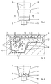
- FIG. 3 shows a further exemplary embodiment of the molding tool 4 with coolant lines 8, which here has different heights or lengths in order to take into account the different solidification times due to the different wall thicknesses d 1 and d 2 of the workpiece 5.
- the cavity 10 and the mandrel 13 of the mold 4 in Fig. 3 is not shown.
- the mold 4 has a greater height h 1 than in the areas 12 with the smaller wall thickness d 2 , where the mold 4 only has the height h 2 .
- an inflow region 14 is provided in the filling device 3, the height h 3 of which corresponds to the difference between the height h 1 of the higher regions 11 and the height h 2 of the shallower regions 12.
Landscapes
- Engineering & Computer Science (AREA)
- Mechanical Engineering (AREA)
- Continuous Casting (AREA)
- Molds, Cores, And Manufacturing Methods Thereof (AREA)
Description
- Fig. 1
- die erfindungsgemäße Vorrichtung zum Stranggießen in einer stark schematisierten Darstellung;
- Fig. 2
- eine erste Ausführungsform des erfindungsgemäßen Formwerkzeugs im Schnitt nach der Linie II-II aus Fig. 1; und
- Fig. 3
- eine zweite Ausführungsform des erfindungsgemäßen Formwerkzeugs in einer Vorderansicht.
Claims (9)
- Vorrichtung (1) zum Stranggießen von in ihrem Innenbereich zumindest eine Hohlraum aufweisenden Werkstücken (5) mit geringen, über den Querschnitt sich verändernden Wandstärken, mit einem Schmelztiegel (2), einer Einfülleinrichtung (3) und mit einem Formwerkzeug (4), welches mit einem Temperierungssystem (7) versehen ist, wobei das Temperierungssystem (7) des Formwerkzeugs (4) so ausgelegt ist, daß Bereiche (11) des herzustellenden Werkstücks (5) mit einer größeren Wandstärke (d1) stärker kühlbar sind, und daß Bereiche (12) des herzustellenden Werkstücks (5) mit einer geringerer Wandstärke (d2) weniger stark kühlbar und/oder beheizbar sind.
- Vorrichtung nach Anspruch 1,
dadurch gekennzeichnet, daß das Temperierungssystem (7) des Formwerkzeugs (4) Kühlmittelleitungen (8) und gegebenenfalls Heizleitungen (9) aufweist. - Vorrichtung nach Anspruch 2,
dadurch gekennzeichnet, daß in den Bereichen (11) des herzustellenden Werkstücks (5) mit einer größeren Wandstärke (d1) eine größere Anzahl von Kühlmittelleitungen (8) vorgesehen sind als in den Bereichen (12) des herzustellenden Werkstücks (5) mit einer geringerer Wandstärke (d2). - Vorrichtung nach Anspruch 2,
dadurch gekennzeichnet, daß in den Bereichen (11) des herzustellenden Werkstücks (5) mit einer größeren Wandstärke (d1) die Kühlmittelleitungen (8) einen größeren Durchmesser aufweisen als in den Bereichen (12) des herzustellenden Werkstücks (5) mit einer geringerer Wandstärke (d2), oder daß in den Bereichen (12) des herzustellenden Werkstücks (5) mit einer geringerer Wandstärke (d2) Heizleitungen (9) vorgesehen sind. - Vorrichtung nach Anspruch 1 oder 2,
dadurch gekennzeichnet, daß das Formwerkzeug (4) in den Bereichen (11) mit der größeren Wandstärke (d1) des herzustellenden Werkstücks (5) mit einer größeren Höhe (h1) als in den Bereichen (12) mit der geringeren Wandstärke (d2) des herzustellenden Werkstücks (5) ausgebildet ist. - Vorrichtung nach Anspruch 5,
dadurch gekennzeichnet, daß in den Bereichen (12) mit niedrigerer Höhe (h2) ein Einfließbereich (14) in der Einfülleinrichtung (3) vorgesehen ist, dessen Höhe (h3) der Differenz zwischen der Höhe (h1) der höheren Bereiche (11) und der Höhe (h2) der flacheren Bereiche (12) entspricht. - Vorrichtung nach einem der Ansprüche 1 bis 6,
dadurch gekennzeichnet, daß das Formwerkzeug (4) einen Dorn (13) aufweist, welcher mit Kühlmittelleitungen (8) und gegebenenfalls Heizleitungen (9) aufweist. - Vorrichtung nach einem der Ansprüche 1 bis 7,
dadurch gekennzeichnet, daß für die Zufuhr der Schmelze (6) in das Formwerkzeug (4) der hydrostatische Druck der Schmelze (6) und/oder ein pulsierender Stempel und/oder ein Extruder vorgesehen ist. - Verfahren zum Stranggießen von in ihrem Innenbereich zumindest eine Hohlraum aufweisenden Werkstücken (5) mit geringen, über den Querschnitt sich verändernden Wandstärken, wobei einem Schmelztiegel (2) Schmelze (6) zugeführt wird, welche in ein mit einem Temperierungssystem (7) versehenes Formwerkzeug (4) eingeführt wird, wobei in dem Formwerkzeug (4) Bereiche (11) des herzustellenden Werkstücks (5) mit einer größeren Wandstärke (d1) stärker gekühlt werden und Bereiche (12) des herzustellenden Werkstücks (5) mit einer geringeren Wandstärke (d2) weniger stark gekühlt und/oder beheizt werden.
Applications Claiming Priority (2)
| Application Number | Priority Date | Filing Date | Title |
|---|---|---|---|
| DE19823797A DE19823797A1 (de) | 1998-05-28 | 1998-05-28 | Vorrichtung und Verfahren zum Stranggießen von Werkstücken |
| DE19823797 | 1998-05-28 |
Publications (2)
| Publication Number | Publication Date |
|---|---|
| EP0968778A1 EP0968778A1 (de) | 2000-01-05 |
| EP0968778B1 true EP0968778B1 (de) | 2004-12-01 |
Family
ID=7869143
Family Applications (1)
| Application Number | Title | Priority Date | Filing Date |
|---|---|---|---|
| EP99110102A Expired - Lifetime EP0968778B1 (de) | 1998-05-28 | 1999-05-25 | Vorrichtung und Verfahren zum Stranggiessen von Werkstücken mit innerem Hohlraum |
Country Status (3)
| Country | Link |
|---|---|
| US (1) | US6401800B1 (de) |
| EP (1) | EP0968778B1 (de) |
| DE (2) | DE19823797A1 (de) |
Families Citing this family (6)
| Publication number | Priority date | Publication date | Assignee | Title |
|---|---|---|---|---|
| DE10031844A1 (de) * | 2000-06-30 | 2002-01-10 | Sms Demag Ag | Stranggießkokille |
| DE102006024778B3 (de) | 2006-03-02 | 2007-07-19 | J. Eberspächer GmbH & Co. KG | Statischer Mischer und Abgasbehandlungseinrichtung |
| CN101490603B (zh) * | 2006-07-14 | 2011-04-20 | 旭硝子株式会社 | 液晶光学器件及其制造方法 |
| EP1918042A1 (de) * | 2006-10-10 | 2008-05-07 | Concast Ag | Stranggiesskokille für Vorprofile |
| JP4829830B2 (ja) * | 2007-03-29 | 2011-12-07 | 株式会社青木科学研究所 | 鍛造用油性潤滑剤、鍛造方法及び塗布装置 |
| DE102015009920A1 (de) | 2015-07-30 | 2016-01-28 | Daimler Ag | Gefäß für eine metallische Schmelze |
Family Cites Families (14)
| Publication number | Priority date | Publication date | Assignee | Title |
|---|---|---|---|---|
| DE429217C (de) * | 1924-03-30 | 1926-05-21 | Jose Merle | Verfahren zur Herstellung von Rohren, Draehten usw |
| DE1900882A1 (de) * | 1969-01-09 | 1970-08-20 | Schloemann Ag | Dorn zum Giessen von metallischen Hohlstraengen |
| US3987655A (en) * | 1975-11-10 | 1976-10-26 | Myotte Robert J | Method of continuously transforming solid non-ferrous metal into elongated extruded shapes |
| US4308908A (en) * | 1980-01-15 | 1982-01-05 | Gus Sevastakis | Methods and apparatus for effecting quick mandrel changes in continuous casting operations |
| JPS57134243A (en) | 1981-02-10 | 1982-08-19 | Nippon Steel Corp | Mold for casting beam blank |
| AT374709B (de) * | 1982-03-23 | 1984-05-25 | Uralsky Politekhn Inst | Halbkontinuierliches stranggiessverfahren fuer metall |
| EP0225523B1 (de) * | 1985-11-30 | 1989-11-15 | Akio Nakano | Druckgiessform zum Gebrauch beim Giessen |
| AT389251B (de) * | 1987-12-23 | 1989-11-10 | Voest Alpine Ind Anlagen | Kuehlung einer stranggiesskokille |
| US5404932A (en) * | 1990-10-17 | 1995-04-11 | Outokumpu Castform Oy | Apparatus and method for intensifying cooling in the casting of metal objects |
| AT396439B (de) * | 1991-05-13 | 1993-09-27 | Sommerhuber Franz | Vorrichtung für den kokillenguss grossdimensionaler profile, insbesondere hohlprofile, aus leichtmetall |
| US5213149A (en) * | 1991-10-10 | 1993-05-25 | Cmi International, Inc. | Mold and method for making variable thickness cast articles |
| DE19529931C1 (de) * | 1995-08-02 | 1997-04-03 | Mannesmann Ag | Plattenkokille zur Erzeugung von Strängen aus Stahl |
| US5771958A (en) * | 1995-09-14 | 1998-06-30 | Ag Industries, Inc. | Mold for continuous casting system |
| DE19549275C1 (de) * | 1995-12-27 | 1997-04-30 | Mannesmann Ag | Stranggießkokille |
-
1998
- 1998-05-28 DE DE19823797A patent/DE19823797A1/de not_active Withdrawn
-
1999
- 1999-05-25 EP EP99110102A patent/EP0968778B1/de not_active Expired - Lifetime
- 1999-05-25 DE DE59911163T patent/DE59911163D1/de not_active Expired - Fee Related
- 1999-05-28 US US09/321,082 patent/US6401800B1/en not_active Expired - Fee Related
Also Published As
| Publication number | Publication date |
|---|---|
| DE19823797A1 (de) | 1999-12-09 |
| DE59911163D1 (de) | 2005-01-05 |
| US6401800B1 (en) | 2002-06-11 |
| EP0968778A1 (de) | 2000-01-05 |
Similar Documents
| Publication | Publication Date | Title |
|---|---|---|
| EP2212089B1 (de) | Extrusionswerkzeug und verfahren zum kühlen extrudierter kunststoffprofile | |
| DE2909848C2 (de) | Vorrichtung zum Stranggießen von Bändern, Knüppeln oder Drähten aus Metall | |
| DE2448256A1 (de) | Verfahren und vorrichtung zur herstellung von hohlkoerpern mit profil durch strangpressen | |
| WO1988001209A1 (fr) | Procede et dispositif de coulee continue de brames | |
| EP0832705A2 (de) | Dünnwandiges, aus Leichtmetall bestehendes Druckgussteil als Strukturbauteil für Karosserien | |
| DE69625360T2 (de) | Herstellung von strangpressmatrizen | |
| EP2025432B2 (de) | Verfahren zur Erzeugung von Stahl-Langprodukten durch Stranggiessen und Walzen | |
| EP0968778B1 (de) | Vorrichtung und Verfahren zum Stranggiessen von Werkstücken mit innerem Hohlraum | |
| EP1052079A1 (de) | Verfahren und Vorrichtung zum Herstellen eines Hohlkammerprofils aus thermoplastischem Kunststoff nach dem Kühldüsenverfahren | |
| CH624861A5 (de) | ||
| DE2902341C2 (de) | Verfahren und Vorrichtung zum Stranggießen von Rohren, insbesondere aus Stahl | |
| DE3330810A1 (de) | Vorrichtung und verfahren zum kontinuierlichen giessen von metall | |
| DE2111763A1 (de) | Strangpressform sowie Verfahren und Vorrichtung zu deren Herstellung | |
| EP1385656B1 (de) | Verfahren zum stranggiessen von blöcken, brammen oder dünnbrammen | |
| DE3856161T2 (de) | Verfahren und vorrichtung zum direkten giessen von metall zur bildung langer körper | |
| EP0972590B1 (de) | Stranggiesskokille | |
| EP0338419B1 (de) | Giess-Schmiede-Verfahren | |
| EP3623074A1 (de) | Verfahren zur endabmessungsnahen herstellung von langprodukten, sowie eine giesswalzanlage zur durchführung des verfahrens | |
| DE19710887C2 (de) | Verwendung einer Kokille zum Herstellen von Barren aus Leichtmetall oder einer Leichtmetallegierung, insbesondere aus Magnesium oder einer Magnesiumlegierung | |
| DE102017127048A1 (de) | Kokille zum Stranggießen | |
| DE4006842A1 (de) | Bandgiessanlage mit oszillierender durchlaufkokille | |
| DE2013345C3 (de) | Von einem Extruder über ein Düsenrohr in Umlaufrichtung gespeiste Spritzgießeinrichtung | |
| DE2402343A1 (de) | Verfahren und vorrichtung zum kontinuierlichen giessen von metallen, insbesondere von stahl | |
| EP0166718B1 (de) | Verfahren und Vorrichtung zum Stranggiessen von metallischen Schmelzen | |
| DE1458013C (de) | Verfahren und Vorrichtung zum konti nuierhchen Herstellen eines in mehrere Teilstrange zerlegbaren, profilierten Stahlstranges 4nm Concast 4G, Zurich (Schweiz) |
Legal Events
| Date | Code | Title | Description |
|---|---|---|---|
| PUAI | Public reference made under article 153(3) epc to a published international application that has entered the european phase |
Free format text: ORIGINAL CODE: 0009012 |
|
| 17P | Request for examination filed |
Effective date: 19991026 |
|
| AK | Designated contracting states |
Kind code of ref document: A1 Designated state(s): DE FR GB IT |
|
| AX | Request for extension of the european patent |
Free format text: AL;LT;LV;MK;RO;SI |
|
| AKX | Designation fees paid |
Free format text: DE FR GB IT |
|
| 17Q | First examination report despatched |
Effective date: 20021021 |
|
| GRAP | Despatch of communication of intention to grant a patent |
Free format text: ORIGINAL CODE: EPIDOSNIGR1 |
|
| GRAS | Grant fee paid |
Free format text: ORIGINAL CODE: EPIDOSNIGR3 |
|
| GRAA | (expected) grant |
Free format text: ORIGINAL CODE: 0009210 |
|
| AK | Designated contracting states |
Kind code of ref document: B1 Designated state(s): DE FR GB IT |
|
| PG25 | Lapsed in a contracting state [announced via postgrant information from national office to epo] |
Ref country code: IT Free format text: LAPSE BECAUSE OF FAILURE TO SUBMIT A TRANSLATION OF THE DESCRIPTION OR TO PAY THE FEE WITHIN THE PRESCRIBED TIME-LIMIT;WARNING: LAPSES OF ITALIAN PATENTS WITH EFFECTIVE DATE BEFORE 2007 MAY HAVE OCCURRED AT ANY TIME BEFORE 2007. THE CORRECT EFFECTIVE DATE MAY BE DIFFERENT FROM THE ONE RECORDED. Effective date: 20041201 Ref country code: GB Free format text: LAPSE BECAUSE OF FAILURE TO SUBMIT A TRANSLATION OF THE DESCRIPTION OR TO PAY THE FEE WITHIN THE PRESCRIBED TIME-LIMIT Effective date: 20041201 Ref country code: FR Free format text: LAPSE BECAUSE OF NON-PAYMENT OF DUE FEES Effective date: 20041201 |
|
| REG | Reference to a national code |
Ref country code: GB Ref legal event code: FG4D Free format text: NOT ENGLISH |
|
| REF | Corresponds to: |
Ref document number: 59911163 Country of ref document: DE Date of ref document: 20050105 Kind code of ref document: P |
|
| GBV | Gb: ep patent (uk) treated as always having been void in accordance with gb section 77(7)/1977 [no translation filed] |
Effective date: 20041201 |
|
| PLBE | No opposition filed within time limit |
Free format text: ORIGINAL CODE: 0009261 |
|
| STAA | Information on the status of an ep patent application or granted ep patent |
Free format text: STATUS: NO OPPOSITION FILED WITHIN TIME LIMIT |
|
| 26N | No opposition filed |
Effective date: 20050902 |
|
| EN | Fr: translation not filed | ||
| PGFP | Annual fee paid to national office [announced via postgrant information from national office to epo] |
Ref country code: DE Payment date: 20090525 Year of fee payment: 11 |
|
| PG25 | Lapsed in a contracting state [announced via postgrant information from national office to epo] |
Ref country code: DE Free format text: LAPSE BECAUSE OF NON-PAYMENT OF DUE FEES Effective date: 20101201 |