EP0968778B1 - Device and method for continuous casting of hollow profiles - Google Patents
Device and method for continuous casting of hollow profiles Download PDFInfo
- Publication number
- EP0968778B1 EP0968778B1 EP99110102A EP99110102A EP0968778B1 EP 0968778 B1 EP0968778 B1 EP 0968778B1 EP 99110102 A EP99110102 A EP 99110102A EP 99110102 A EP99110102 A EP 99110102A EP 0968778 B1 EP0968778 B1 EP 0968778B1
- Authority
- EP
- European Patent Office
- Prior art keywords
- regions
- workpiece
- wall thickness
- possess
- produced
- Prior art date
- Legal status (The legal status is an assumption and is not a legal conclusion. Google has not performed a legal analysis and makes no representation as to the accuracy of the status listed.)
- Expired - Lifetime
Links
Images
Classifications
-
- B—PERFORMING OPERATIONS; TRANSPORTING
- B22—CASTING; POWDER METALLURGY
- B22D—CASTING OF METALS; CASTING OF OTHER SUBSTANCES BY THE SAME PROCESSES OR DEVICES
- B22D11/00—Continuous casting of metals, i.e. casting in indefinite lengths
- B22D11/04—Continuous casting of metals, i.e. casting in indefinite lengths into open-ended moulds
- B22D11/055—Cooling the moulds
-
- B—PERFORMING OPERATIONS; TRANSPORTING
- B22—CASTING; POWDER METALLURGY
- B22D—CASTING OF METALS; CASTING OF OTHER SUBSTANCES BY THE SAME PROCESSES OR DEVICES
- B22D11/00—Continuous casting of metals, i.e. casting in indefinite lengths
- B22D11/009—Continuous casting of metals, i.e. casting in indefinite lengths of work of special cross-section, e.g. I-beams, U-profiles
-
- B—PERFORMING OPERATIONS; TRANSPORTING
- B22—CASTING; POWDER METALLURGY
- B22D—CASTING OF METALS; CASTING OF OTHER SUBSTANCES BY THE SAME PROCESSES OR DEVICES
- B22D11/00—Continuous casting of metals, i.e. casting in indefinite lengths
- B22D11/04—Continuous casting of metals, i.e. casting in indefinite lengths into open-ended moulds
- B22D11/0406—Moulds with special profile
Definitions
- the invention relates to a device and a method for continuous casting of in their interior at least with a cavity having workpieces small, over the cross section changing wall thicknesses.
- DE-PS 429 217 is a process for the preparation of pipes, wires, etc. known, which the known centrifugal casting with the well-known Extrusion method connects.
- DE 31 50 684 C2 describes a semi-continuous Continuous casting process for metals with upward stripping strand.
- Fig. 1 is a device 1 for continuous casting with a crucible 2, a filling device 3 and a mold 4 shown. From the mold 4 enters at its bottom through Continuously casting manufactured workpiece 5 or this is deducted by appropriate facilities.
- melt 6 filled, which in this case by their own hydrostatic pressure via the filling device 3 enters the mold 4.
- a pulsating pressure generator such as. a stamp or an extruder
- the delivery of the Melt 6 thereby also take place in the horizontal direction. From the melt 6 is formed in the mold. 4 by solidification the workpiece 5.
- the temperature control system 7 has coolant lines 8 and in the present case also heating cables 9.
- the temperature control system 7 is intended, the melt 6 and the workpiece 5 to cool so that until the escape of Workpiece 5 at the bottom of the mold. 4 forms a uniform, symmetrical solidification front and no distortion of the workpiece 5 is formed. Much more this occurs straight from the mold. 4 out.
- the workpiece 5, which is formed by a cavity 10 in the mold 4, has in its cross-section areas 11 with a larger wall thickness d 1 and areas 12 with a smaller wall thickness d 2 .
- areas 11 with greater wall thicknesses d 1 there are more coolant lines 8 than in the areas 12 with the smaller wall thickness d 2 , where, if appropriate, heating lines 9 can also be located.
- the regions 11 with the larger wall thicknesses d 1 require a longer solidification time than the regions 12 with the smaller wall thicknesses d 2 .
- the coolant lines 8 and the heating cables 9 must be arranged and matched to one another so that the workpiece 5 uniformly solidifies. However, for example, in the regions 11 on the walls to the mold 4, a faster solidification will still occur than in the middle of the regions 11, so that the solidification front will run here in the manner of a parabola.
- the workpiece 5 is a one Hollow profile with a recess in its interior, why the mold 4 is also a se known mandrel 13 which also with Coolant lines 8 and possibly with heating cables 9 is provided. Instead of the mandrel 13 could alternatively also a well-known bridge matrix be provided. These could also be with coolant lines 8 and optionally provided with heating cables 9 his.
- the coolant lines 8 in the areas 11 with greater wall thickness d 1 have a larger diameter than the coolant lines 8 in the areas 12 with a smaller wall thickness d 2 .
- An adaptation of the volume flow in the coolant lines 8 and the heating cables 9 to the necessary cooling of the workpiece 5 is possible.
- the regions 11 of the workpiece 5 with the larger wall thickness d 1 are cooled more strongly than the regions 12 of the workpiece 5 with the smaller wall thickness d 2 .
- the uniformly solidifying layer of the workpiece 5 that results at the lower edge of the molding tool 4 workpieces 5 of any desired cross section can be produced by the molding tool 4, in particular with different wall thicknesses varying over the cross section and with at least one cavity in its inner region.
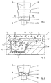
- FIG. 3 shows a further exemplary embodiment of the molding tool 4 with coolant lines 8, which here has different heights or lengths in order to take into account the different solidification times due to the different wall thicknesses d 1 and d 2 of the workpiece 5.
- the cavity 10 and the mandrel 13 of the mold 4 in Fig. 3 is not shown.
- the mold 4 has a greater height h 1 than in the areas 12 with the smaller wall thickness d 2 , where the mold 4 only has the height h 2 .
- an inflow region 14 is provided in the filling device 3, the height h 3 of which corresponds to the difference between the height h 1 of the higher regions 11 and the height h 2 of the shallower regions 12.
Description
Die Erfindung betrifft eine Vorrichtung und ein Verfahren zum Stranggießen von in ihrem Innenbereich zumindest einen Hohlraum aufweisenden Werkstücken mit geringen, über den Querschnitt sich verändernden Wandstärken.The invention relates to a device and a method for continuous casting of in their interior at least with a cavity having workpieces small, over the cross section changing wall thicknesses.
Aus der DE 195 29 931 C1 ist eine Plattenkokille zur Erzeugung von Strängen aus Stahl bekannt, bei welcher die Breitseitenwände mindestens drei nebeneinander liegende und voneinander unabhängige Kühlsegmente aufweisen. Hierdurch soll es möglich sein, eine differenzierte Aussage über den partiellen Wärmestrom über die Kokillenbreite zu machen.From DE 195 29 931 C1 is a plate mold for Production of steel strands known in which the broad side walls at least three next to each other have lying and independent cooling segments. This should make it possible, a differentiated Statement about the partial heat flow over the Mold width to make.
Die DE 32 04 339 A1 beschreibt eine Stranggußkokille zum Gießen von Trägerrohlingen, welche mit Kühlmittelleitungen versehen ist.DE 32 04 339 A1 describes a continuous casting mold for casting carrier blanks, which with coolant lines is provided.
Eine weitere Vorrichtung sowie ein entsprechendes Verfahren sind aus der DE-OS 26 50 016 bekannt. Bei diesem als Extrudieren bezeichneten Verfahren wird aus einem flüssigen Metall in einem Formwerkzeug, in diesem Fall als Extrudiermatrize bezeichnet, als Werkstück ein Endlosstrang abgezogen.Another device and a corresponding method are known from DE-OS 26 50 016. In this The process referred to as extruding is made a liquid metal in a mold, in this Case referred to as Extrudiermatrize, as a workpiece an endless strand deducted.
Aus der DE-PS 429 217 ist ein Verfahren zur Herstellung von Rohren, Drähten usw. bekannt, welches das bekannte Schleudergußverfahren mit dem ebenfalls bekannten Strangpreßverfahren verbindet.From DE-PS 429 217 is a process for the preparation of pipes, wires, etc. known, which the known centrifugal casting with the well-known Extrusion method connects.
Des weiteren beschreibt die DE 31 50 684 C2 ein halbkontinuierliches Stranggießverfahren für Metalle mit nach oben abzuziehendem Strang. Durch das dort beschriebene, sehr komplizierte Verfahren soll sichergestellt werden, daß sich auch aus komplexen Legierungen seigerungsfreie Stränge ausgezeichneter Qualität bei hoher Produktionsleistung herstellen lassen.Furthermore, DE 31 50 684 C2 describes a semi-continuous Continuous casting process for metals with upward stripping strand. By the one described there, very complicated procedures should be ensured that are also made of complex alloys segregation-free strands of excellent quality high production output.
Durch sämtliche der oben beschriebenen Verfahren und Vorrichtungen ist es nachteiligerweise nicht möglich, Werkstücke mit komplizierten Querschnitten, welche insbesondere unterschiedliche Dicken aufweisen, durch Stranggießen herzustellen.Through all of the methods described above and Devices are disadvantageously not possible Workpieces with complicated cross sections, which in particular, have different thicknesses, through To produce continuous casting.
Die Verfahren Stranggießen und Strangpressen sind außer aus den oben genannten Schriften auch aus dem allgemeinen Stand der Technik bekannt. Um beliebige, je nach Verwendungszweck teilweise recht komplizierte Profile herzustellen, wird meist ein Halbzeug durch Stranggießen hergestellt und anschließend durch Strangpressen in die endgültige Form gebracht.The processes continuous casting and extrusion are out of the question from the above-mentioned writings also from the general Known in the art. Any, ever according to purpose partly quite complicated Producing profiles is usually a semi-finished by Continuous casting and then by Extruders brought into the final shape.
Der hohe Fertigungsaufwand und die damit verbundenen hohen Kosten dieses Verfahrens und der dabei verwendeten Vorrichtungen sind jedoch sehr nachteilig.The high production costs and the associated high cost of this process and the one used However, devices are very disadvantageous.
Es ist daher Aufgabe der vorliegenden Erfindung, eine Vorrichtung und ein Verfahren zum Stranggießen zu schaffen, mit welchen auch Werkstücke von kompliziertem Querschnitt mit unterschiedlichen, über den Querschnitt sich verändernden Dicken bzw. Wandstärken hergestellt werden können.It is therefore an object of the present invention to provide a Apparatus and method for continuous casting create, with which also workpieces of complicated Cross section with different, across the cross section made of varying thicknesses or wall thicknesses can be.
Erfindungsgemäß wird diese Aufgabe durch die in Anspruch
1 genannten Merkmale gelöst.According to the invention this object is achieved by the
Eine verfahrensmäßige Lösung ergibt sich aus den in Anspruch 9 genannten Merkmalen.A procedural solution results from the in Claim 9 mentioned features.
Durch die erfindungsgemäße Auslegung des Temperierungssystems des Formwerkzeugs können nunmehr Bereiche des herzustellenden Werkstücks mit größerer Wandstärke stärker gekühlt werden und Bereiche mit geringerer Wandstärke können weniger stark gekühlt oder sogar beheizt werden. Dadurch ist es möglich, Werkstücke mit beliebigem, insbesondere mit kompliziertem Querschnitt durch Stranggießen herzustellen, da die Erstarrungsfront, also der Bereich in dem die Schmelze in das fertige Werkstück übergeht, trotz der unterschiedlichen Wandstärken nunmehr gleichmäßig über den Querschnitt verteilt ist. Man könnte auch von einem symmetrisch Verlauf der Erstarrungsfront über den Querschnitt sprechen, bei dem das Mittel der zuletzt erstarrenden Bereiche sich in der Art einer Kraftresultierenden im Mittelpunkt des Werkstücks befindet..Vorteilhafterweise tritt nunmehr der gegossene Strang geradlinig aus dem Formwerkzeug aus. Due to the inventive design of Temperierungssystems of the mold can now areas of the workpiece to be produced with greater wall thickness be cooled more and areas with lesser Wall thickness can be cooled less or even less be heated. This makes it possible to workpieces with Any, especially with a complicated cross-section by continuous casting, since the solidification front, So the area where the melt in the finished workpiece passes, despite the different Wall thicknesses now evenly across the cross section is distributed. You could also think of a symmetrical Course of the solidification front over the cross section speak, in which the means of the last solidifying Areas are in the nature of a force-resultant located in the center of the workpiece .. Advantageously now comes the cast strand straight from the mold.
Die bisherige Problematik, daß Bereiche mit größerer Wandstärke eine längere Erstarrungszeit haben als Bereiche mit geringerer Wandstärke und dadurch sehr starker Verzug an dem aus der Kokille austretenden Strang auftreten würde, ist somit nicht mehr gegeben.The previous problem that areas with larger Wall thickness have a longer solidification time than areas with a smaller wall thickness and therefore very strong distortion on the emerging from the mold Strand would occur, is thus no longer given.
Durch das erfindungsgemäße Verfahren ist es möglich, auf das Strangpressen zu verzichten, das bisher zusätzlich zum Stranggießen notwendig war, um Werkstücke mit komplizierteren Querschnitten herzustellen.By the method according to the invention it is possible to dispense with the extruding, so far in addition for continuous casting was necessary to workpieces produce with more complicated cross sections.
Eine vorteilhafte Ausführungsform der Erfindung geht
aus den Unteransprüchen 2 bis 4 hervor.An advantageous embodiment of the invention is
from the
Durch das Anpassen der Anzahl bzw. des Durchmessers der Kühlmittelleitungen bzw. der Heizleitungen ergibt sich eine einfache konstruktive Umsetzung der erfindungsgemäßen Auslegung des Temperierungssystems.By adjusting the number or diameter the coolant lines and the heating cables results a simple structural implementation of the invention Design of the temperature control system.
Eine alternative Möglichkeit der Ausführung des erfindungsgemäßen
Temperierungssystems des Formwerkzeugs
ergibt sich aus den Unteransprüchen 5 und 6.An alternative way of carrying out the invention
Temperature control system of the mold
arises from the
Durch die geringere Höhe bzw. Länge des Formwerkzeugs in den Werkstückbereichen mit geringerer Wandstärke ergibt sich eine geringere wirksame Höhe des Temperierungssystems, welches somit einen geringeren Kühleffekt in den Bereichen mit geringerer Wandstärke des herzustellenden Werkstücks erzeugt.Due to the lower height or length of the mold in the workpiece areas with a smaller wall thickness results in a lower effective height of the tempering system, which thus a lower cooling effect in the areas with lower wall thickness of produced workpiece produced.
Weitere vorteilhafte Ausgestaltungen der Erfindung ergeben sich aus den weiteren Unteransprüchen und aus dem nachfolgend anhand der Zeichnung prinzipmäßig dargestellten Ausführungsbeispiel.Further advantageous embodiments of the invention emerge from the other dependent claims and from in the following with reference to the drawing in principle Embodiment.
Es zeigt:
- Fig. 1
- die erfindungsgemäße Vorrichtung zum Stranggießen in einer stark schematisierten Darstellung;
- Fig. 2
- eine erste Ausführungsform des erfindungsgemäßen Formwerkzeugs im Schnitt nach der Linie II-II aus Fig. 1; und
- Fig. 3
- eine zweite Ausführungsform des erfindungsgemäßen Formwerkzeugs in einer Vorderansicht.
- Fig. 1
- the inventive apparatus for continuous casting in a highly schematic representation;
- Fig. 2
- a first embodiment of the mold according to the invention in section along the line II-II of Fig. 1; and
- Fig. 3
- a second embodiment of the mold according to the invention in a front view.
Gemäß Fig. 1 ist eine Vorrichtung 1 zum Stranggießen
mit einem Schmelztiegel 2, einer Einfülleinrichtung 3
und einem Formwerkzeug 4 dargestellt. Aus dem Formwerkzeug
4 tritt an dessen Unterseite ein durch
Stranggießen hergestelltes Werkstück 5 aus bzw. dieses
wird durch geeignete Einrichtungen abgezogen.According to Fig. 1 is a
In den Schmelztiegel 2 wird an dessen Oberseite
Schmelze 6 eingefüllt, welche in diesem Fall durch
ihren eigenen hydrostatischen Druck über die Einfülleinrichtung
3 in das Formwerkzeug 4 gelangt. In
nicht dargestellter Art und Weise wäre es auch möglich,
die Schmelze 6 über einen pulsierenden Druckerzeuger,
wie z.B. einen Stempel oder einen Extruder,
dem Formwerkzeug 4 zuzuführen. Dies wäre insbesondere
dann sinnvoll, wenn höhere Preßkräfte erforderlich
wären. In beiden Fällen könnte die Zuführung der
Schmelze 6 dabei auch in horizontaler Richtung erfolgen.
Aus der Schmelze 6 entsteht in dem Formwerkzeug 4
durch Erstarrung das Werkstück 5.In the
Fig. 2 zeigt einen Schnitt durch das Formwerkzeug 4,
welches in an sich bekannter Weise mit einem Temperierungssystem
7 versehen ist. Das Temperierungssystem 7
weist Kühlmittelleitungen 8 und im vorliegenden Fall
auch Heizleitungen 9 auf. Das Temperierungssystem 7
ist dafür vorgesehen, die Schmelze 6 bzw. das Werkstück
5 so abzukühlen, daß sich bis zum Austreten des
Werkstücks 5 an der Unterseite des Formwerkzeugs 4
eine gleichmäßige, symmetrische Erstarrungsfront bildet
und kein Verzug des Werkstücks 5 entsteht. Vielmehr
tritt dieses geradlinig aus dem Formwerkzeug 4
aus.2 shows a section through the
Das Werkstück 5, welches durch einen Hohlraum 10 in
dem Formwerkzeug 4 gebildet wird, weist in seinem
Querschnitt Bereiche 11 mit einer größeren Wandstärke
d1 und Bereiche 12 mit einer geringeren Wandstärke d2
auf. In den Bereichen 11 mit größeren Wandstärken d1
befinden sich mehr Kühlmittelleitungen 8 als in den
Bereichen 12 mit der geringeren Wandstärke d2, wo sich
gegebenenfalls auch Heizleitungen 9 befinden können.The
Dies ist der Fall, weil die Bereiche 11 mit den größeren
Wandstärken d1 eine längere Erstarrungszeit benötigen
als die Bereiche 12 mit den geringeren Wandstärken
d2. Die Kühlmittelleitungen 8 und die Heizleitungen
9 müssen so angeordnet und aufeinander abgestimmt
sein, daß das Werkstück 5 gleichmäßig erstarrt. Es
wird jedoch beispielsweise in den Bereichen 11 an den
Wänden zu dem Formwerkzeug 4 noch immer zu einer
schnelleren Erstarrung kommen als in der Mitte der
Bereiche 11, so daß die Erstarrungsfront hier in der
Art einer Parabel verlaufen wird. Am Ausgang aus dem
Formwerkzeug 4 ist zumindest die äußere Schale des
Werkstücks 5 erstarrt, es kann jedoch bereits im Formwerkzeug
4 ein vollständig durcherstarrtes Werkstück 5
vorliegen.This is the case because the
Bei dem Werkstück 5 handelt es sich hierbei um ein
Hohlprofil mit einer Aussparung in seinem Innenbereich,
weshalb das Formwerkzeug 4 auch einen an sich
bekannten Dorn 13 aufweist, welcher ebenfalls mit
Kühlmittelleitungen 8 und gegebenenfalls mit Heizleitungen
9 versehen ist. Statt des Dorns 13 könnte alternativ
auch eine ebenfalls bekannte Brückenmatrize
vorgesehen sein. Auch diese könnte mit Kühlmittelleitungen
8 und gegebenenfalls mit Heizleitungen 9 versehen
sein.The
In einem nicht dargestellten Ausführungsbeispiel kann
auch vorgesehen sein, daß die Kühlmittelleitungen 8 in
den Bereichen 11 mit größerer Wandstärke d1 einen größeren
Durchmesser aufweisen als die Kühlmittelleitungen
8 in den Bereichen 12 mit geringerer Wandstärke
d2. Auch eine Anpassung des Volumenstroms in den Kühlmittelleitungen
8 bzw. den Heizleitungen 9 an die notwendige
Kühlung des Werkstücks 5 ist möglich.In one embodiment, not shown, it may also be provided that the
Durch die beiden beschriebenen Anordnungen werden die
Bereiche 11 des Werkstücks 5 mit der größeren Wandstärke
d1 stärker gekühlt als die Bereiche 12 des
Werkstücks 5 mit der geringerer Wandstärke d2. Durch
die sich am unteren Rand des Formwerkzeuges 4 ergebende
gleichmäßig erstarrende Schicht des Werkstücks 5
können durch das Formwerkzeug 4 Werkstücke 5 mit beliebigem
Querschnitt hergestellt werden, insbesondere
mit unterschiedlichen, sich über den Querschnitt verändernden
Wandstärken und mit zumindest einem Hohlraum
in ihrem Innenbereich.As a result of the two arrangements described, the
Fig. 3 zeigt eine weiteres Ausführungsbeispiel des
Formwerkzeugs 4 mit Kühlmittelleitungen 8, welches
hier verschiedene Höhen bzw. Längen aufweist, um die
unterschiedlichen Erstarrungszeiten durch die unterschiedlichen
Wandstärken d1 und d2 des Werkstücks 5 zu
berücksichtigen. Aus Übersichtlichkeitsgründen ist der
Hohlraum 10 und der Dorn 13 des Formwerkzeugs 4 in
Fig. 3 nicht dargestellt. In den Bereichen 11 (nicht
dargestellt) mit der größeren Wandstärke d1 des herzustellenden
Werkstücks 5 weist das Formwerkzeug 4 eine
größere Höhe h1 auf als in den Bereichen 12 mit der
geringeren Wandstärke d2, wo das Formwerkzeug 4 lediglich
die Höhe h2 aufweist. In den Bereichen 12 mit
niedrigerer Höhe h2 ist in der Einfülleinrichtung 3
ein Einfließbereich 14 vorgesehen, dessen Höhe h3 der
Differenz zwischen der Höhe h1 der höheren Bereiche 11
und der Höhe h2 der flacheren Bereiche 12 entspricht.3 shows a further exemplary embodiment of the
Bei Werkstücken 5 mit sehr komplizierten Querschnitten
können sich selbstverständlich noch weitere Höhendifferenzen
der entsprechenden Bereiche ergeben, so daß
letztendlich ein Formwerkzeug 4 mit einer vollständig
an das Werkstück 5 angepaßten Kontur entsteht.For
In den Bereichen 11 ergibt sich somit eine stärkere
Kühlung durch die Kühlmittelleitungen 8 als in den
Bereichen 12, die aufgrund ihrer geringen Höhe h2 auch
kürzere Kühlmittelleitungen 8 aufweisen.In the
Somit ist auch durch dieses Formwerkzeug 4 die Herstellung
von Werkstücken 5 mit beliebigen Querschnitten
durch Stranggießen möglich, und es muß nicht wie
bisher ein zusätzlicher Arbeitsschritt, nämlich das
Strangpressen, durchgeführt werden.Thus, the production is also by this
Selbstverständlich ist es auch möglich, sowohl unterschiedliche
Höhen des Formwerkzeugs 4 als auch die
oben beschriebene Verteilung der Kühlmittelleitungen 8
und der Heizleitungen 9 miteinander in einem Formwerkzeug
4 zu kombinieren.Of course it is also possible, both different
Heights of the
Claims (9)
- Apparatus (1) for the continuous casting of workpieces (5) having at least one cavity in their inner region and possessing small wall thicknesses varying over the cross section, with a crucible (2), with a filling device (3) and with a moulding die (4) which is provided with a thermal control system (7), the thermal control system (7) of the moulding die (4) being designed in such a way that regions (11) of the workpiece (5) to be produced which possess a greater wall thickness (d1) can be cooled to a greater extent, and in such a way that regions (12) of the workpiece (5) to be reduced which possess a smaller wall thickness (d2) can be cooled to a lesser extent and/or can be heated.
- Apparatus according to Claim 1, characterized in that the thermal control system (7) of the moulding die (4) has coolant lines (8) and, if appropriate, heating lines (9).
- Apparatus according to Claim 2, characterized in that a larger number of coolant lines (8) are provided in the regions (11) of the workpiece (5) to be produced which possess a greater wall thickness (d1) than in the regions (12) of the workpiece (5) to be produced which possess a smaller wall thickness (d2).
- Apparatus according to Claim 2, characterized in that the coolant lines (8) have a larger diameter in the regions (11) of the workpiece (5) to be produced which possess a greater wall thickness (d1) than in the regions (12) of the workpiece (5) to be produced which possess a smaller wall thickness (d2), or in that heating lines (9) are provided in the regions (12) of the workpiece (5) to be produced which possess a smaller wall thickness (d2).
- Apparatus according to Claim 1 or 2, characterized in that the moulding die (4) is designed with a greater height (h1) in the regions (11) of the workpiece (5) to be produced which possess a greater wall thickness (d1) than in the regions (12) of the workpiece (5) to be produced which possess the smaller wall thickness (d2).
- Apparatus according to Claim 5, characterized in that the filling device (3) has provided in it, in the regions (12) possessing a lower height (h2), an inflow region (14), the height (h3) of which corresponds to the difference between the height (h1) of the higher regions (11) and the height (h2) of the flatter regions (12).
- Apparatus according to one of Claims 1 to 6, characterized in that the moulding die (4) has a mandrel (13) which is provided with coolant lines (8) and, if appropriate, heating lines (9).
- Apparatus according to one of Claims 1 to 7, characterized in that, for feeding the melt (6) into the moulding die (4), the hydrostatic pressure of the melt (6) and/or a pulsating plunger and/or an extruder is provided.
- Method for continuous casting of workpieces (5) having at least one cavity in their inner region and possessing small wall thicknesses varying over the cross section, a crucible (2) being fed with a melt (6) which is introduced into a moulding die (4) provided with a thermal control system (7), in the moulding die (4) regions (11) of the workpiece (5) to be produced which possess a greater wall thickness (d1) being cooled to a greater extent and regions (12) of the workpiece (5) to be produced which possess a smaller wall thickness (d2) being cooled to a lesser extent and/or being heated.
Applications Claiming Priority (2)
| Application Number | Priority Date | Filing Date | Title |
|---|---|---|---|
| DE19823797 | 1998-05-28 | ||
| DE19823797A DE19823797A1 (en) | 1998-05-28 | 1998-05-28 | Apparatus and method for continuous casting of workpieces |
Publications (2)
| Publication Number | Publication Date |
|---|---|
| EP0968778A1 EP0968778A1 (en) | 2000-01-05 |
| EP0968778B1 true EP0968778B1 (en) | 2004-12-01 |
Family
ID=7869143
Family Applications (1)
| Application Number | Title | Priority Date | Filing Date |
|---|---|---|---|
| EP99110102A Expired - Lifetime EP0968778B1 (en) | 1998-05-28 | 1999-05-25 | Device and method for continuous casting of hollow profiles |
Country Status (3)
| Country | Link |
|---|---|
| US (1) | US6401800B1 (en) |
| EP (1) | EP0968778B1 (en) |
| DE (2) | DE19823797A1 (en) |
Families Citing this family (6)
| Publication number | Priority date | Publication date | Assignee | Title |
|---|---|---|---|---|
| DE10031844A1 (en) * | 2000-06-30 | 2002-01-10 | Sms Demag Ag | Continuous casting mold comprises a copper plate fitting the progress of the casting cross-section for a profiled casting cross-section with holes for coolant in the casting direction and collection holes opening out into water tanks |
| DE102006024778B3 (en) | 2006-03-02 | 2007-07-19 | J. Eberspächer GmbH & Co. KG | Static mixer for exhaust system of internal combustion engine, has flow conducting surfaces arranged at web materials so that surfaces are arranged with cells at their diverting side and extend in direction of flow in tube |
| WO2008007715A1 (en) * | 2006-07-14 | 2008-01-17 | Asahi Glass Company, Limited | Liquid crystal optical device and process for manufacturing the same |
| EP1918042A1 (en) * | 2006-10-10 | 2008-05-07 | Concast Ag | Mould for continuous casting of pre-profiled billets |
| JP4829830B2 (en) * | 2007-03-29 | 2011-12-07 | 株式会社青木科学研究所 | Oil-based lubricant for forging, forging method and coating apparatus |
| DE102015009920A1 (en) | 2015-07-30 | 2016-01-28 | Daimler Ag | Vessel for a metallic melt |
Family Cites Families (14)
| Publication number | Priority date | Publication date | Assignee | Title |
|---|---|---|---|---|
| DE429217C (en) * | 1924-03-30 | 1926-05-21 | Jose Merle | Process for the production of pipes, wires, etc. |
| DE1900882A1 (en) * | 1969-01-09 | 1970-08-20 | Schloemann Ag | Mandrel for casting metallic hollow bars |
| US3987655A (en) | 1975-11-10 | 1976-10-26 | Myotte Robert J | Method of continuously transforming solid non-ferrous metal into elongated extruded shapes |
| US4308908A (en) * | 1980-01-15 | 1982-01-05 | Gus Sevastakis | Methods and apparatus for effecting quick mandrel changes in continuous casting operations |
| JPS57134243A (en) * | 1981-02-10 | 1982-08-19 | Nippon Steel Corp | Mold for casting beam blank |
| AT374709B (en) * | 1982-03-23 | 1984-05-25 | Uralsky Politekhn Inst | SEMI-CONTINUOUS CONTINUOUS CASTING METHOD |
| EP0225523B1 (en) * | 1985-11-30 | 1989-11-15 | Akio Nakano | Molding die for use in casting |
| AT389251B (en) * | 1987-12-23 | 1989-11-10 | Voest Alpine Ind Anlagen | COOLING OF A CONTINUOUS CASTING CHILL |
| US5404932A (en) * | 1990-10-17 | 1995-04-11 | Outokumpu Castform Oy | Apparatus and method for intensifying cooling in the casting of metal objects |
| AT396439B (en) * | 1991-05-13 | 1993-09-27 | Sommerhuber Franz | Apparatus for permanent-mould casting of sections of large dimensions, in particular hollow sections, from light alloy |
| US5213149A (en) * | 1991-10-10 | 1993-05-25 | Cmi International, Inc. | Mold and method for making variable thickness cast articles |
| DE19529931C1 (en) * | 1995-08-02 | 1997-04-03 | Mannesmann Ag | Plate mold for the production of steel strands |
| US5771958A (en) * | 1995-09-14 | 1998-06-30 | Ag Industries, Inc. | Mold for continuous casting system |
| DE19549275C1 (en) * | 1995-12-27 | 1997-04-30 | Mannesmann Ag | Concasting mould for making profile sections |
-
1998
- 1998-05-28 DE DE19823797A patent/DE19823797A1/en not_active Withdrawn
-
1999
- 1999-05-25 DE DE59911163T patent/DE59911163D1/en not_active Expired - Fee Related
- 1999-05-25 EP EP99110102A patent/EP0968778B1/en not_active Expired - Lifetime
- 1999-05-28 US US09/321,082 patent/US6401800B1/en not_active Expired - Fee Related
Also Published As
| Publication number | Publication date |
|---|---|
| DE19823797A1 (en) | 1999-12-09 |
| US6401800B1 (en) | 2002-06-11 |
| DE59911163D1 (en) | 2005-01-05 |
| EP0968778A1 (en) | 2000-01-05 |
Similar Documents
| Publication | Publication Date | Title |
|---|---|---|
| EP2212089B1 (en) | Extrusion die and method for cooling an extruded plastic profile | |
| DE2909848C2 (en) | Device for continuous casting of strips, billets or wires made of metal | |
| DE2448256A1 (en) | METHOD AND DEVICE FOR MANUFACTURING HOLLOW BODIES WITH PROFILE BY EXTRUSION PRESSES | |
| WO1988001209A1 (en) | Process and device for continuous casting of slabs | |
| EP0832705A2 (en) | Thin-walled casting made of light metal alloy, produced by die-casting as structural element for car bodies | |
| EP0968778B1 (en) | Device and method for continuous casting of hollow profiles | |
| CH624861A5 (en) | ||
| DE3330810A1 (en) | DEVICE AND METHOD FOR CONTINUOUSLY POURING METAL | |
| DE2902341C2 (en) | Method and device for the continuous casting of pipes, in particular made of steel | |
| DE2111763A1 (en) | Extrusion mold and method and device for their production | |
| EP2025432B2 (en) | Method for creating steel long products through strand casting and rolling | |
| EP1385656B1 (en) | Method for continuously casting ingots, slabs or thin slabs | |
| EP0972590B1 (en) | Continuous casting mould | |
| EP0338419B1 (en) | Squeeze-casting method | |
| DE19710887C2 (en) | Use of a mold for the production of bars from light metal or a light metal alloy, in particular from magnesium or a magnesium alloy | |
| EP0107069A1 (en) | Method of continuously casting metals, in particular steel, and continuous-casting plants for carrying out the method | |
| DE4006842A1 (en) | Strip casting assembly - has die head with flow guides to prevent turbulence in molten metal passing to the mouthpiece | |
| EP3623074A1 (en) | Method for the preparation of long products which are close to final dimensions and a continuous casting and rolling installation for carrying out the method | |
| DE2013345C3 (en) | Injection molding device fed by an extruder through a nozzle tube in the direction of rotation | |
| DE2402343A1 (en) | Continuous casting of steel sections - includes lateral combined cooling and squeeze-ing of section after leaving mould | |
| DE102017127048A1 (en) | Mold for continuous casting | |
| EP0166718B1 (en) | Method of and installation for continuous casting of metallic melts | |
| DE1458013C (en) | Method and device for the continuous production of a profiled steel strand 4nm Concast 4G, which can be divided into several partial strands, Zurich (Switzerland) | |
| EP0846510B1 (en) | Use of a mould for producing bars of light metal or their alloys, especially magnesium or magnesium alloy | |
| DE2123331A1 (en) | Process for the production of a plate made of thermoplastic material in lightweight construction and device for carrying out this process |
Legal Events
| Date | Code | Title | Description |
|---|---|---|---|
| PUAI | Public reference made under article 153(3) epc to a published international application that has entered the european phase |
Free format text: ORIGINAL CODE: 0009012 |
|
| 17P | Request for examination filed |
Effective date: 19991026 |
|
| AK | Designated contracting states |
Kind code of ref document: A1 Designated state(s): DE FR GB IT |
|
| AX | Request for extension of the european patent |
Free format text: AL;LT;LV;MK;RO;SI |
|
| AKX | Designation fees paid |
Free format text: DE FR GB IT |
|
| 17Q | First examination report despatched |
Effective date: 20021021 |
|
| GRAP | Despatch of communication of intention to grant a patent |
Free format text: ORIGINAL CODE: EPIDOSNIGR1 |
|
| GRAS | Grant fee paid |
Free format text: ORIGINAL CODE: EPIDOSNIGR3 |
|
| GRAA | (expected) grant |
Free format text: ORIGINAL CODE: 0009210 |
|
| AK | Designated contracting states |
Kind code of ref document: B1 Designated state(s): DE FR GB IT |
|
| PG25 | Lapsed in a contracting state [announced via postgrant information from national office to epo] |
Ref country code: IT Free format text: LAPSE BECAUSE OF FAILURE TO SUBMIT A TRANSLATION OF THE DESCRIPTION OR TO PAY THE FEE WITHIN THE PRESCRIBED TIME-LIMIT;WARNING: LAPSES OF ITALIAN PATENTS WITH EFFECTIVE DATE BEFORE 2007 MAY HAVE OCCURRED AT ANY TIME BEFORE 2007. THE CORRECT EFFECTIVE DATE MAY BE DIFFERENT FROM THE ONE RECORDED. Effective date: 20041201 Ref country code: GB Free format text: LAPSE BECAUSE OF FAILURE TO SUBMIT A TRANSLATION OF THE DESCRIPTION OR TO PAY THE FEE WITHIN THE PRESCRIBED TIME-LIMIT Effective date: 20041201 Ref country code: FR Free format text: LAPSE BECAUSE OF NON-PAYMENT OF DUE FEES Effective date: 20041201 |
|
| REG | Reference to a national code |
Ref country code: GB Ref legal event code: FG4D Free format text: NOT ENGLISH |
|
| REF | Corresponds to: |
Ref document number: 59911163 Country of ref document: DE Date of ref document: 20050105 Kind code of ref document: P |
|
| GBV | Gb: ep patent (uk) treated as always having been void in accordance with gb section 77(7)/1977 [no translation filed] |
Effective date: 20041201 |
|
| PLBE | No opposition filed within time limit |
Free format text: ORIGINAL CODE: 0009261 |
|
| STAA | Information on the status of an ep patent application or granted ep patent |
Free format text: STATUS: NO OPPOSITION FILED WITHIN TIME LIMIT |
|
| 26N | No opposition filed |
Effective date: 20050902 |
|
| EN | Fr: translation not filed | ||
| PGFP | Annual fee paid to national office [announced via postgrant information from national office to epo] |
Ref country code: DE Payment date: 20090525 Year of fee payment: 11 |
|
| PG25 | Lapsed in a contracting state [announced via postgrant information from national office to epo] |
Ref country code: DE Free format text: LAPSE BECAUSE OF NON-PAYMENT OF DUE FEES Effective date: 20101201 |