EP0968359B1 - Dispositif de reglage de charge - Google Patents
Dispositif de reglage de charge Download PDFInfo
- Publication number
- EP0968359B1 EP0968359B1 EP98906934A EP98906934A EP0968359B1 EP 0968359 B1 EP0968359 B1 EP 0968359B1 EP 98906934 A EP98906934 A EP 98906934A EP 98906934 A EP98906934 A EP 98906934A EP 0968359 B1 EP0968359 B1 EP 0968359B1
- Authority
- EP
- European Patent Office
- Prior art keywords
- torsion spring
- support part
- adjustment device
- load adjustment
- designed
- Prior art date
- Legal status (The legal status is an assumption and is not a legal conclusion. Google has not performed a legal analysis and makes no representation as to the accuracy of the status listed.)
- Expired - Lifetime
Links
- 238000002485 combustion reaction Methods 0.000 claims description 4
- 230000002441 reversible effect Effects 0.000 claims description 3
- 238000005452 bending Methods 0.000 description 1
- 238000003780 insertion Methods 0.000 description 1
- 230000037431 insertion Effects 0.000 description 1
- 230000003993 interaction Effects 0.000 description 1
Images


Classifications
-
- F—MECHANICAL ENGINEERING; LIGHTING; HEATING; WEAPONS; BLASTING
- F02—COMBUSTION ENGINES; HOT-GAS OR COMBUSTION-PRODUCT ENGINE PLANTS
- F02D—CONTROLLING COMBUSTION ENGINES
- F02D9/00—Controlling engines by throttling air or fuel-and-air induction conduits or exhaust conduits
- F02D9/02—Controlling engines by throttling air or fuel-and-air induction conduits or exhaust conduits concerning induction conduits
- F02D2009/0201—Arrangements; Control features; Details thereof
- F02D2009/0269—Throttle closing springs; Acting of throttle closing springs on the throttle shaft
-
- F—MECHANICAL ENGINEERING; LIGHTING; HEATING; WEAPONS; BLASTING
- F02—COMBUSTION ENGINES; HOT-GAS OR COMBUSTION-PRODUCT ENGINE PLANTS
- F02D—CONTROLLING COMBUSTION ENGINES
- F02D9/00—Controlling engines by throttling air or fuel-and-air induction conduits or exhaust conduits
- F02D9/02—Controlling engines by throttling air or fuel-and-air induction conduits or exhaust conduits concerning induction conduits
- F02D2009/0201—Arrangements; Control features; Details thereof
- F02D2009/0277—Fail-safe mechanisms, e.g. with limp-home feature, to close throttle if actuator fails, or if control cable sticks or breaks
Definitions
- the invention relates to a load adjustment device with a power controlling an internal combustion engine, in particular as a throttle valve trained, arranged on an actuator shaft, the Actuating shaft by means of a reversible actuator between one Minimum load position and a full load position is pivotally driven, and with a single, as a return spring for biasing the control shaft in Minimum load direction and as an emergency running spring for pretensioning the actuating shaft against a run-flat stop torsion spring, the first end with the control shaft and its second end with an arm one between a minimum load stop and the emergency stop can be moved Support part is connected or connectable.
- a load adjustment device with a power controlling an internal combustion engine, in particular as a throttle valve trained, arranged on an actuator shaft, the Actuating shaft by means of a reversible actuator between one Minimum load position and a full load position is pivotally driven, and with a single, as a return spring for biasing the control shaft in Minimum load direction and as an emergency running spring for pretensioning the actuating shaft against a
- Load adjustment devices of the above type are generally under the Designation E-gas for power adjustment of the internal combustion engine from Motor vehicles known.
- the load adjustment device is special as an emergency spring and as a return spring compact design and particularly light in weight.
- a disadvantage of the known load adjustment device is that the ends of the Torsion spring can be attached to the adjusting shaft and the support part must, since the torsion spring acting in both directions of rotation of the control shaft Actuates. Furthermore, vibrations of the motor vehicle can increase loosen the fastenings of the torsion spring.
- the control shaft usually has a slot in the torsion spring is inserted.
- the invention is based on the problem of a load adjustment device of the type mentioned in such a way that they are particularly inexpensive is constructed and that the torsion spring is particularly reliable the support part is attached.
- This design allows the torsion spring in both directions Actuating shaft transferring acting forces to the support part without it can detach itself from the support part. Vibrations of the Motor vehicle also no longer lead to a loosening of the torsion spring from the support part. As a result, the torsion spring is positive and thus attached particularly reliably to the support part. Grasping one Part of the support part by the torsion spring is compared for screwing particularly inexpensive.
- the torsion spring is attached to the support part in accordance with an advantageous development of the invention is particularly constructive simply when the second end of the torsion spring pivots the support member is designed around. This must result in the second end of the Torsion spring for assembly is simply plugged onto the pin of the support part become.
- the second end of the torsion spring is advantageous according to another Further development of the invention on the support part is particularly reliable held when the second end of the torsion spring is bent in a U-shape and at its free end a spring tongue pointing towards the base of the U. Has.
- Disengaging the second end of the torsion spring from the pin of the support member in the direction of the axis of the pin can be according to another simply avoid advantageous development of the invention if the pin of the support part spans the second end of the torsion spring is designed.
- the second end of the torsion spring is advantageous according to another Development of the invention secured in all directions against loosening, if the pin of the support part has a recess for receiving the second end of the torsion spring.
- the torsion spring is according to another advantageous development Invention simply secured against tilting when the support member has a base plate for guiding the torsion spring.
- a jamming of the torsion spring on an edge of the support part can be done according to another advantageous development of the invention, if the support part has several in its radially outer regions Has stops to limit the radial extent of the torsion spring.
- the invention permits numerous embodiments.
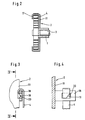
- the housing connector 1 shows a load adjustment device with a pivotable on a housing stub 1 supported part 2.
- the center of the housing connector 1 is an adjusting shaft 3, which is, for example around a throttle valve shaft with a not shown Throttle valve can act, also pivotally mounted.
- the control shaft 3, which is welded to the support part 2, for example, or a Forms unit is connected to the support part 2 via a torsion spring 4 and can by a reversible actuator 5 via a To simplify the drawing, pivot the gear (not shown).
- the actuator 5 has a driver 6 for deflecting one Swivel arm 7 of the support part 2.
- the support part 2 has a stop arm 8 on the movement of the support member 2 between a Minimum load stop 9 and an emergency stop 10 limited.
- the support part 2 has a base plate 11 for guiding the torsion spring 4 and in its radially outer areas several stops 12 to 14 for limitation the radial extension of the torsion spring 4.
- the actuating shaft 3 has a slot 15 for fastening the torsion spring 4 in which one end of the torsion spring 4 is inserted.
- the second The end of the torsion spring 4 is bent in a U-shape and has one in the direction of The base of the U-pointing spring tongue 16 for engaging behind a pin 17 of the support part 2.
- FIG. 3 shows a further embodiment of the fastening of the Torsion spring 4 on the support part 2.
- the support part 2 has a vertical to the base plate 11 arranged pin 18.
- the pin 18 will encompassed by a U-shaped end of a torsion spring 4.
- the End of the torsion spring 4 has a bend 19 for engaging in one Recess 20 of the pin 18.
- Figure 4 illustrates in a sectional view along the line IV - IV by Figure 3 the attachment of the torsion spring 4 on the pin 18. Here it can be seen that the bend 19 from a corner of the free end the torsion spring 4 is formed.
- the pin 17 of the support member 2 is the second End of the torsion spring 4 is designed to span.
- the torsion spring 4 has a bevel 21 at its second end in the longitudinal direction on.
- the pin 17 has a bend 22, for example, by Stamping from the originally straight pin 17 is formed.
- the Slant 21 of the torsion spring 4 and the slope of the bend 22 run parallel, the bend 22 overlaps the slope 21 of the torsion spring, so that the torsion spring 4 after insertion under tension from the interplay of bevel 21 and overall bending 22 is fixed in position.
- FIG. 6 illustrates in a sectional illustration along the line V - V through Figure 5 the attachment of the torsion spring 4 on the pin 17.
- the bend 22 the second end of the torsion spring 4th overlaps.
- the assembly takes place, for example, in such a way that the torsion spring is held under tension by an assembly tool and that U-shaped second end (when viewing Figure 6 from the left) at a distance is brought to the pin 17 and then moved laterally, so that the slope 21 gets under the bend 22.
- the torsion spring 4 is under its target tension and thereby pulls the slope 21 further under the bend 22 until the position is fixed.
Landscapes
- Engineering & Computer Science (AREA)
- Chemical & Material Sciences (AREA)
- Combustion & Propulsion (AREA)
- Mechanical Engineering (AREA)
- General Engineering & Computer Science (AREA)
- Springs (AREA)
- Control Of Throttle Valves Provided In The Intake System Or In The Exhaust System (AREA)
Claims (9)
- Dispositif de réglage de charge comportant un organe de réglage fixé à un arbre de commande et commandant la puissance d'un moteur à combustion interne, cet organe ayant en particulier la forme d'un papillon des gaz, l'arbre de commande pouvant être entraíné en rotation au moyen d'un actionneur réversible entre une position de charge minimale et une position de pleine charge, ce dispositif comportant également un ressort de rotation unique agissant comme ressort de rappel pour solliciter l'arbre de commande en direction de la charge minimale et comme ressort de marche d'urgence pour solliciter l'arbre de commande contre une butée de marche d'urgence, la première extrémité de ce ressort étant ou pouvant être reliée à l'arbre de commande et la seconde extrémité de ce ressort étant ou pouvant être reliée à une pièce d'appui mobile entre une butée de charge minimale et la butée de marche d'urgence, la seconde extrémité du ressort de rotation (4) étant conçue pour s'accrocher sur une partie (téton 17, 18) de la pièce d'appui (2), caractérisé en ce que la pièce d'appui (2) est fabriquée d'une seule pièce avec les butées (12 à 14) et le téton (17, 18), et le téton (17) de la pièce d'appui (2) étant conçu pour saisir par-dessus la seconde extrémité du ressort de rotation (4) de manière que le ressort de rotation (4) comporte à sa seconde extrémité dans le sens de la longueur un chanfrein (21) et le téton (17) un repliement (22).
- Dispositif de réglage de charge selon la revendication 1, caractérisé en ce que la seconde extrémité du ressort de rotation (4) est conçue pour enserrer un téton (17, 18) de la pièce de support (2).
- Dispositif de réglage de charge selon la revendication 1 ou 2, caractérisé en ce que la seconde extrémité du ressort de rotation (4) est courbée en forme de U et a à un son extrémité libre une languette de ressort (16) orientée en direction de la base du U.
- Dispositif de réglage de charge selon la revendication 3, caractérisé en ce que la languette de ressort (16) fait un angle avec le ressort de rotation (4).
- Dispositif de réglage de charge selon l'une au moins des revendications précédentes, caractérisé en ce que le téton (17) de la pièce d'appui (2) est conçu pour saisir par-dessus la seconde extrémité du ressort de rotation (4).
- Dispositif de réglage de charge selon l'une au moins des revendications précédentes, caractérisé en ce que le téton (18) de la pièce d'appui (2) comporte un évidement (20) pour recevoir la seconde extrémité (repliement 19) du ressort de rotation (4).
- Dispositif de réglage de charge selon l'une au moins des revendications précédentes, caractérisé en ce que la pièce d'appui (2) comporte une plaque de base (11) pour le guidage du ressort de rotation (4).
- Dispositif de réglage de charge selon l'une au moins des revendications précédentes, caractérisé en ce que la pièce d'appui (2) comporte dans ses zones radialement extérieures plusieurs butées (12 à 14) pour la limitation de l'étendue radiale du ressort de rotation (4).
- Dispositif de réglage de charge selon la revendication 8, caractérisé en ce que les butées (12 à 14) sont conçues pour saisir par-dessus le ressort de rotation (4).
Applications Claiming Priority (3)
| Application Number | Priority Date | Filing Date | Title |
|---|---|---|---|
| DE19711408 | 1997-03-19 | ||
| DE19711408A DE19711408A1 (de) | 1997-03-19 | 1997-03-19 | Lastverstellvorrichtung |
| PCT/EP1998/000675 WO1998041745A1 (fr) | 1997-03-19 | 1998-02-07 | Dispositif de reglage de charge |
Publications (2)
| Publication Number | Publication Date |
|---|---|
| EP0968359A1 EP0968359A1 (fr) | 2000-01-05 |
| EP0968359B1 true EP0968359B1 (fr) | 2002-10-02 |
Family
ID=7823877
Family Applications (1)
| Application Number | Title | Priority Date | Filing Date |
|---|---|---|---|
| EP98906934A Expired - Lifetime EP0968359B1 (fr) | 1997-03-19 | 1998-02-07 | Dispositif de reglage de charge |
Country Status (5)
| Country | Link |
|---|---|
| US (1) | US6279533B1 (fr) |
| EP (1) | EP0968359B1 (fr) |
| JP (1) | JP2001516415A (fr) |
| DE (2) | DE19711408A1 (fr) |
| WO (1) | WO1998041745A1 (fr) |
Families Citing this family (3)
| Publication number | Priority date | Publication date | Assignee | Title |
|---|---|---|---|---|
| US20160024998A1 (en) * | 2013-03-15 | 2016-01-28 | Borgwarner Inc. | A compact rotary wastegate valve |
| JP6392146B2 (ja) * | 2015-03-10 | 2018-09-19 | 愛三工業株式会社 | スロットル装置 |
| CN112816193B (zh) * | 2020-12-30 | 2023-05-02 | 嘉兴毅拓汽车科技有限公司 | 一种用于电控执行器的可变负载耐久测试装置及测试方法 |
Family Cites Families (9)
| Publication number | Priority date | Publication date | Assignee | Title |
|---|---|---|---|---|
| DE2728022A1 (de) | 1977-06-22 | 1979-01-18 | Alfred Von Schuckmann | Beschlag zur neigungsverstellung der lehne von sitz- bzw. liegemoebeln |
| FR2639679B1 (fr) | 1988-11-25 | 1994-02-11 | Solex | Dispositif de commande d'organe d'etranglement pour installation d'alimentation en combustible de moteur a combustion interne |
| DE4013823C2 (de) | 1990-04-30 | 1993-11-18 | Vdo Schindling | Rückstelleinheit für die Drosselklappe einer Brennkraftmaschine |
| JPH0684729B2 (ja) | 1990-07-27 | 1994-10-26 | 日本電装株式会社 | 内燃機関のスロットル弁開閉装置 |
| DE4132653A1 (de) | 1991-10-01 | 1993-04-08 | Vdo Schindling | Drehfederanordnung |
| DE4315010A1 (de) | 1993-05-06 | 1994-11-10 | Bosch Gmbh Robert | Betätigungsvorrichtung für ein Drosselorgan |
| DE19519836C5 (de) * | 1995-05-31 | 2010-10-14 | Continental Automotive Gmbh | Lastverstelleinrichtung |
| DE19524941B4 (de) * | 1995-07-08 | 2006-05-18 | Siemens Ag | Lastverstellvorrichtung |
| US5820178A (en) * | 1996-07-19 | 1998-10-13 | Baldwin Hardware Corporation | Spring retainer for lock mechanism |
-
1997
- 1997-03-19 DE DE19711408A patent/DE19711408A1/de not_active Withdrawn
-
1998
- 1998-02-07 WO PCT/EP1998/000675 patent/WO1998041745A1/fr not_active Ceased
- 1998-02-07 EP EP98906934A patent/EP0968359B1/fr not_active Expired - Lifetime
- 1998-02-07 JP JP54005798A patent/JP2001516415A/ja not_active Abandoned
- 1998-02-07 DE DE59805803T patent/DE59805803D1/de not_active Expired - Fee Related
- 1998-02-07 US US09/381,565 patent/US6279533B1/en not_active Expired - Fee Related
Also Published As
| Publication number | Publication date |
|---|---|
| DE59805803D1 (de) | 2002-11-07 |
| DE19711408A1 (de) | 1998-10-01 |
| EP0968359A1 (fr) | 2000-01-05 |
| US6279533B1 (en) | 2001-08-28 |
| WO1998041745A1 (fr) | 1998-09-24 |
| JP2001516415A (ja) | 2001-09-25 |
Similar Documents
| Publication | Publication Date | Title |
|---|---|---|
| DE102018130993B4 (de) | Abgasstrangventil mit vereinfachter Kopplung zwischen Stellglied und Klappe sowie Verfahren zum Montieren eines derartigen Ventils | |
| EP0792218B1 (fr) | Module pedale d'accelerateur | |
| DE112012002539B4 (de) | Stellkraft-Übertragungseinrichtung eines Abgasturboladers | |
| DE19524941B4 (de) | Lastverstellvorrichtung | |
| EP0565768A1 (fr) | Frein à main muni de rajustage automatique | |
| DE19536605A1 (de) | Fahrpedalmodul | |
| DE19536606A1 (de) | Fahrpedalmodul | |
| EP0828932B1 (fr) | Dispositif de commande pour assurer la commande de la puissance d'un moteur entrainement | |
| DE3218325A1 (de) | Kupplungsausruecklager, insbesondere fuer kraftfahrzeuge | |
| EP0968359B1 (fr) | Dispositif de reglage de charge | |
| DE102007021633A1 (de) | Handgeführtes Arbeitsgerät | |
| EP1186523B1 (fr) | Dispositif de changement de vitesse pour bicyclette | |
| EP1063403A2 (fr) | Dispositif de commande de charge | |
| EP1005608A1 (fr) | Dispositif d'ajustement de charge | |
| DE4436096C2 (de) | Klinkenschaltwerk zum Antrieb einer Verstellvorrichtungen für einen Fahrzeugsitz | |
| DE29904620U1 (de) | Antriebsvorrichtung für ein Stellglied | |
| EP0981461A1 (fr) | Entrainement a effet bilateral | |
| EP1356197A1 (fr) | Dispositif pour repositionner un element rotatif | |
| EP1077843A1 (fr) | Organe d'entrainement d'essuie-glace comportant un moteur a engrenage reversible | |
| EP0230516A2 (fr) | Dispositif de commande de l'organe de réglage de la puissance d'un moteur à combustion interne | |
| EP1191170A1 (fr) | Dispositif de verrouillage pour une porte de véhicule | |
| EP1569830B1 (fr) | Commande d'essuie-glace | |
| EP0989293B1 (fr) | Dispositif de commande de charge | |
| DE10230188A1 (de) | Spannsystem für einen Zugmitteltrieb | |
| DE2603651A1 (de) | Gaspedal fuer kraftfahrzeuge |
Legal Events
| Date | Code | Title | Description |
|---|---|---|---|
| PUAI | Public reference made under article 153(3) epc to a published international application that has entered the european phase |
Free format text: ORIGINAL CODE: 0009012 |
|
| 17P | Request for examination filed |
Effective date: 19990909 |
|
| AK | Designated contracting states |
Kind code of ref document: A1 Designated state(s): DE FR GB |
|
| 17Q | First examination report despatched |
Effective date: 20010528 |
|
| RAP1 | Party data changed (applicant data changed or rights of an application transferred) |
Owner name: SIEMENS AKTIENGESELLSCHAFT |
|
| GRAG | Despatch of communication of intention to grant |
Free format text: ORIGINAL CODE: EPIDOS AGRA |
|
| GRAG | Despatch of communication of intention to grant |
Free format text: ORIGINAL CODE: EPIDOS AGRA |
|
| GRAH | Despatch of communication of intention to grant a patent |
Free format text: ORIGINAL CODE: EPIDOS IGRA |
|
| GRAH | Despatch of communication of intention to grant a patent |
Free format text: ORIGINAL CODE: EPIDOS IGRA |
|
| GRAA | (expected) grant |
Free format text: ORIGINAL CODE: 0009210 |
|
| AK | Designated contracting states |
Kind code of ref document: B1 Designated state(s): DE FR GB |
|
| REG | Reference to a national code |
Ref country code: GB Ref legal event code: FG4D Free format text: NOT ENGLISH |
|
| REF | Corresponds to: |
Ref document number: 59805803 Country of ref document: DE Date of ref document: 20021107 |
|
| GBT | Gb: translation of ep patent filed (gb section 77(6)(a)/1977) |
Effective date: 20021223 |
|
| ET | Fr: translation filed | ||
| PLBE | No opposition filed within time limit |
Free format text: ORIGINAL CODE: 0009261 |
|
| STAA | Information on the status of an ep patent application or granted ep patent |
Free format text: STATUS: NO OPPOSITION FILED WITHIN TIME LIMIT |
|
| 26N | No opposition filed |
Effective date: 20030703 |
|
| PGFP | Annual fee paid to national office [announced via postgrant information from national office to epo] |
Ref country code: GB Payment date: 20050208 Year of fee payment: 8 |
|
| PGFP | Annual fee paid to national office [announced via postgrant information from national office to epo] |
Ref country code: FR Payment date: 20050224 Year of fee payment: 8 |
|
| PG25 | Lapsed in a contracting state [announced via postgrant information from national office to epo] |
Ref country code: GB Free format text: LAPSE BECAUSE OF NON-PAYMENT OF DUE FEES Effective date: 20060207 |
|
| GBPC | Gb: european patent ceased through non-payment of renewal fee |
Effective date: 20060207 |
|
| REG | Reference to a national code |
Ref country code: FR Ref legal event code: ST Effective date: 20061031 |
|
| PG25 | Lapsed in a contracting state [announced via postgrant information from national office to epo] |
Ref country code: FR Free format text: LAPSE BECAUSE OF NON-PAYMENT OF DUE FEES Effective date: 20060228 |
|
| PGFP | Annual fee paid to national office [announced via postgrant information from national office to epo] |
Ref country code: DE Payment date: 20090219 Year of fee payment: 12 |
|
| PG25 | Lapsed in a contracting state [announced via postgrant information from national office to epo] |
Ref country code: DE Free format text: LAPSE BECAUSE OF NON-PAYMENT OF DUE FEES Effective date: 20100901 |