EP0968359B1 - Load adjustment device - Google Patents
Load adjustment device Download PDFInfo
- Publication number
- EP0968359B1 EP0968359B1 EP98906934A EP98906934A EP0968359B1 EP 0968359 B1 EP0968359 B1 EP 0968359B1 EP 98906934 A EP98906934 A EP 98906934A EP 98906934 A EP98906934 A EP 98906934A EP 0968359 B1 EP0968359 B1 EP 0968359B1
- Authority
- EP
- European Patent Office
- Prior art keywords
- torsion spring
- support part
- adjustment device
- load adjustment
- designed
- Prior art date
- Legal status (The legal status is an assumption and is not a legal conclusion. Google has not performed a legal analysis and makes no representation as to the accuracy of the status listed.)
- Expired - Lifetime
Links
- 238000002485 combustion reaction Methods 0.000 claims description 4
- 230000002441 reversible effect Effects 0.000 claims description 3
- 238000005452 bending Methods 0.000 description 1
- 238000003780 insertion Methods 0.000 description 1
- 230000037431 insertion Effects 0.000 description 1
- 230000003993 interaction Effects 0.000 description 1
Images


Classifications
-
- F—MECHANICAL ENGINEERING; LIGHTING; HEATING; WEAPONS; BLASTING
- F02—COMBUSTION ENGINES; HOT-GAS OR COMBUSTION-PRODUCT ENGINE PLANTS
- F02D—CONTROLLING COMBUSTION ENGINES
- F02D9/00—Controlling engines by throttling air or fuel-and-air induction conduits or exhaust conduits
- F02D9/02—Controlling engines by throttling air or fuel-and-air induction conduits or exhaust conduits concerning induction conduits
- F02D2009/0201—Arrangements; Control features; Details thereof
- F02D2009/0269—Throttle closing springs; Acting of throttle closing springs on the throttle shaft
-
- F—MECHANICAL ENGINEERING; LIGHTING; HEATING; WEAPONS; BLASTING
- F02—COMBUSTION ENGINES; HOT-GAS OR COMBUSTION-PRODUCT ENGINE PLANTS
- F02D—CONTROLLING COMBUSTION ENGINES
- F02D9/00—Controlling engines by throttling air or fuel-and-air induction conduits or exhaust conduits
- F02D9/02—Controlling engines by throttling air or fuel-and-air induction conduits or exhaust conduits concerning induction conduits
- F02D2009/0201—Arrangements; Control features; Details thereof
- F02D2009/0277—Fail-safe mechanisms, e.g. with limp-home feature, to close throttle if actuator fails, or if control cable sticks or breaks
Definitions
- the invention relates to a load adjustment device with a power controlling an internal combustion engine, in particular as a throttle valve trained, arranged on an actuator shaft, the Actuating shaft by means of a reversible actuator between one Minimum load position and a full load position is pivotally driven, and with a single, as a return spring for biasing the control shaft in Minimum load direction and as an emergency running spring for pretensioning the actuating shaft against a run-flat stop torsion spring, the first end with the control shaft and its second end with an arm one between a minimum load stop and the emergency stop can be moved Support part is connected or connectable.
- a load adjustment device with a power controlling an internal combustion engine, in particular as a throttle valve trained, arranged on an actuator shaft, the Actuating shaft by means of a reversible actuator between one Minimum load position and a full load position is pivotally driven, and with a single, as a return spring for biasing the control shaft in Minimum load direction and as an emergency running spring for pretensioning the actuating shaft against a
- Load adjustment devices of the above type are generally under the Designation E-gas for power adjustment of the internal combustion engine from Motor vehicles known.
- the load adjustment device is special as an emergency spring and as a return spring compact design and particularly light in weight.
- a disadvantage of the known load adjustment device is that the ends of the Torsion spring can be attached to the adjusting shaft and the support part must, since the torsion spring acting in both directions of rotation of the control shaft Actuates. Furthermore, vibrations of the motor vehicle can increase loosen the fastenings of the torsion spring.
- the control shaft usually has a slot in the torsion spring is inserted.
- the invention is based on the problem of a load adjustment device of the type mentioned in such a way that they are particularly inexpensive is constructed and that the torsion spring is particularly reliable the support part is attached.
- This design allows the torsion spring in both directions Actuating shaft transferring acting forces to the support part without it can detach itself from the support part. Vibrations of the Motor vehicle also no longer lead to a loosening of the torsion spring from the support part. As a result, the torsion spring is positive and thus attached particularly reliably to the support part. Grasping one Part of the support part by the torsion spring is compared for screwing particularly inexpensive.
- the torsion spring is attached to the support part in accordance with an advantageous development of the invention is particularly constructive simply when the second end of the torsion spring pivots the support member is designed around. This must result in the second end of the Torsion spring for assembly is simply plugged onto the pin of the support part become.
- the second end of the torsion spring is advantageous according to another Further development of the invention on the support part is particularly reliable held when the second end of the torsion spring is bent in a U-shape and at its free end a spring tongue pointing towards the base of the U. Has.
- Disengaging the second end of the torsion spring from the pin of the support member in the direction of the axis of the pin can be according to another simply avoid advantageous development of the invention if the pin of the support part spans the second end of the torsion spring is designed.
- the second end of the torsion spring is advantageous according to another Development of the invention secured in all directions against loosening, if the pin of the support part has a recess for receiving the second end of the torsion spring.
- the torsion spring is according to another advantageous development Invention simply secured against tilting when the support member has a base plate for guiding the torsion spring.
- a jamming of the torsion spring on an edge of the support part can be done according to another advantageous development of the invention, if the support part has several in its radially outer regions Has stops to limit the radial extent of the torsion spring.
- the invention permits numerous embodiments.
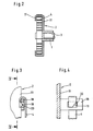
- the housing connector 1 shows a load adjustment device with a pivotable on a housing stub 1 supported part 2.
- the center of the housing connector 1 is an adjusting shaft 3, which is, for example around a throttle valve shaft with a not shown Throttle valve can act, also pivotally mounted.
- the control shaft 3, which is welded to the support part 2, for example, or a Forms unit is connected to the support part 2 via a torsion spring 4 and can by a reversible actuator 5 via a To simplify the drawing, pivot the gear (not shown).
- the actuator 5 has a driver 6 for deflecting one Swivel arm 7 of the support part 2.
- the support part 2 has a stop arm 8 on the movement of the support member 2 between a Minimum load stop 9 and an emergency stop 10 limited.
- the support part 2 has a base plate 11 for guiding the torsion spring 4 and in its radially outer areas several stops 12 to 14 for limitation the radial extension of the torsion spring 4.
- the actuating shaft 3 has a slot 15 for fastening the torsion spring 4 in which one end of the torsion spring 4 is inserted.
- the second The end of the torsion spring 4 is bent in a U-shape and has one in the direction of The base of the U-pointing spring tongue 16 for engaging behind a pin 17 of the support part 2.
- FIG. 3 shows a further embodiment of the fastening of the Torsion spring 4 on the support part 2.
- the support part 2 has a vertical to the base plate 11 arranged pin 18.
- the pin 18 will encompassed by a U-shaped end of a torsion spring 4.
- the End of the torsion spring 4 has a bend 19 for engaging in one Recess 20 of the pin 18.
- Figure 4 illustrates in a sectional view along the line IV - IV by Figure 3 the attachment of the torsion spring 4 on the pin 18. Here it can be seen that the bend 19 from a corner of the free end the torsion spring 4 is formed.
- the pin 17 of the support member 2 is the second End of the torsion spring 4 is designed to span.
- the torsion spring 4 has a bevel 21 at its second end in the longitudinal direction on.
- the pin 17 has a bend 22, for example, by Stamping from the originally straight pin 17 is formed.
- the Slant 21 of the torsion spring 4 and the slope of the bend 22 run parallel, the bend 22 overlaps the slope 21 of the torsion spring, so that the torsion spring 4 after insertion under tension from the interplay of bevel 21 and overall bending 22 is fixed in position.
- FIG. 6 illustrates in a sectional illustration along the line V - V through Figure 5 the attachment of the torsion spring 4 on the pin 17.
- the bend 22 the second end of the torsion spring 4th overlaps.
- the assembly takes place, for example, in such a way that the torsion spring is held under tension by an assembly tool and that U-shaped second end (when viewing Figure 6 from the left) at a distance is brought to the pin 17 and then moved laterally, so that the slope 21 gets under the bend 22.
- the torsion spring 4 is under its target tension and thereby pulls the slope 21 further under the bend 22 until the position is fixed.
Landscapes
- Engineering & Computer Science (AREA)
- Chemical & Material Sciences (AREA)
- Combustion & Propulsion (AREA)
- Mechanical Engineering (AREA)
- General Engineering & Computer Science (AREA)
- Springs (AREA)
- Control Of Throttle Valves Provided In The Intake System Or In The Exhaust System (AREA)
Description
Die Erfindung betrifft eine Lastverstelleinrichtung mit einem die Leistung einer Brennkraftmaschine steuernden, insbesondere als Drosselklappe ausgebildeten, auf einer Stellwelle angeordneten Stellglied, wobei die Stellwelle mittels eines reversierbaren Stellantriebs zwischen einer Minimallaststellung und einer Volllaststellung schwenkbar antreibbar ist, und mit einer einzigen, als Rückstellfeder zur Vorspannung der Stellwelle in Minimallastrichtung und als Notlauffeder zur Vorspannung der Stellwelle gegen einen Notlaufanschlag ausgebildeten Drehfeder, deren erstes Ende mit der Stellwelle und deren zweites Ende mit einem Arm eines zwischen einem Minimallast-Anschlag und dem Notlaufanschlag bewegbaren Abstützteil verbunden oder verbindbar ist.The invention relates to a load adjustment device with a power controlling an internal combustion engine, in particular as a throttle valve trained, arranged on an actuator shaft, the Actuating shaft by means of a reversible actuator between one Minimum load position and a full load position is pivotally driven, and with a single, as a return spring for biasing the control shaft in Minimum load direction and as an emergency running spring for pretensioning the actuating shaft against a run-flat stop torsion spring, the first end with the control shaft and its second end with an arm one between a minimum load stop and the emergency stop can be moved Support part is connected or connectable.
Lastverstellvorrichtungen der vorstehenden Art sind allgemein unter der Bezeichnung E-Gas zur Leistungsverstellung der Brennkraftmaschine von Kraftfahrzeugen bekannt. Durch den Einsatz einer einzigen Drehfeder als Notlauffeder und als Rückstellfeder ist die Lastverstellvorrichtung besonders kompakt aufgebaut und weist ein besonders geringes Gewicht auf.Load adjustment devices of the above type are generally under the Designation E-gas for power adjustment of the internal combustion engine from Motor vehicles known. By using a single torsion spring as The load adjustment device is special as an emergency spring and as a return spring compact design and particularly light in weight.
Aus der DE 195 24 941 A1 ist eine Lastverstellvorrichtung für ein die Leistung einer Brennkraftmaschine bestimmtes Stellglied bekannt, daß auf einer Stellwelle einen drehbar gelagerten Anschlaghebel aufweist. Dabei ist eine Drehfeder zwischen diesem Anschlaghebel und der Stellwelle gespannt. Hierzu umschließt ein annähernd U-förmig gebogenes Ende der Drehfeder einen Zapfen des Anschlaghebels teilweise. Ebenfalls eine Befestigung einer Drehfeder mittels eines annähemd U-förmig gebogenen Endes an einem festen Element beschreibt die DE 27 28 022 A1.From DE 195 24 941 A1 is a load adjustment device for the Performance of an internal combustion engine certain actuator known to an actuating shaft has a rotatably mounted stop lever. It is a torsion spring between this stop lever and the actuating shaft curious; excited. For this purpose, an approximately U-shaped end encloses the Torsion spring partially a pin of the stop lever. Another one Attachment of a torsion spring by means of an approximately U-shaped curve DE 27 28 022 A1 describes the end of a fixed element.
Nachteilig bei der bekannten Lastverstellvorrichtung ist, daß die Enden der Drehfeder aufwendig an der Stellwelle und dem Abstützteil befestigt werden müssen, da die Drehfeder in beide Drehrichtungen der Stellwelle wirkende Stellkräfte ausübt. Weiterhin können Vibrationen des Kraftfahrzeuges zu einem Lösen der Befestigungen der Drehfeder führen. Zur Befestigung der Drehfeder an der Stellwelle hat die Stellwelle in der Regel einen Schlitz, in den die Drehfeder eingesteckt wird. A disadvantage of the known load adjustment device is that the ends of the Torsion spring can be attached to the adjusting shaft and the support part must, since the torsion spring acting in both directions of rotation of the control shaft Actuates. Furthermore, vibrations of the motor vehicle can increase loosen the fastenings of the torsion spring. To attach the Torsion spring on the control shaft, the control shaft usually has a slot in the torsion spring is inserted.
Man könnte daran denken, das zweite Ende der Drehfeder an dem Abstützteil festzuschrauben. Hierdurch gestaltet sich die Lastverstellvorrichtung jedoch besonders kostenintensiv. Weiterhin kann sich eine Schraube durch Vibrationen lösen, so daß dann die Drehfeder keine Verbindung mehr mit dem Abstützteil hätte.One could think of the second end of the torsion spring on the support member tighten. As a result, the load adjustment device is designed however, it is particularly expensive. Furthermore, a screw loosen by vibrations so that the torsion spring then no connection would have more with the support part.
Der Erfindung liegt das Problem zugrunde, eine Lastverstellvorrichtung der eingangs genannten Art so zu gestalten, daß sie besonders kostengünstig aufgebaut ist und daß die Drehfeder besonders zuverlässig an dem Abstützteil befestigt ist.The invention is based on the problem of a load adjustment device of the type mentioned in such a way that they are particularly inexpensive is constructed and that the torsion spring is particularly reliable the support part is attached.
Dieses Problem wird erfindungsgemäß gelöst mit den Merkmalen gemäß Anspruch 1.This problem is invented solved with the features according to Claim 1.
Durch diese Gestaltung kann die Drehfeder in beide Richtungen der Stellwelle wirkende Stellkräfte auf das Abstützteil übertragen, ohne daß sie sich selbständig von dem Abstützteil lösen kann. Vibrationen des Kraftfahrzeugs führen ebenfalls nicht mehr zu einem Lösen der Drehfeder von dem Abstützteil. Hierdurch ist die Drehfeder formschlüssig und damit besonders zuverlässig an dem Abstützteil befestigt. Das Hintergreifen eines Teilstücks des Abstützteils durch die Drehfeder gestaltet sich im Vergleich zu einem Verschrauben besonders kostengünstig.This design allows the torsion spring in both directions Actuating shaft transferring acting forces to the support part without it can detach itself from the support part. Vibrations of the Motor vehicle also no longer lead to a loosening of the torsion spring from the support part. As a result, the torsion spring is positive and thus attached particularly reliably to the support part. Grasping one Part of the support part by the torsion spring is compared for screwing particularly inexpensive.
Die Befestigung der Drehfeder an dem Abstützteil gestaltet sich gemäß einer vorteilhaften Weiterbildung der Erfindung konstruktiv besonders einfach, wenn das zweite Ende der Drehfeder einen Zapfen des Abstützteils umschließend gestaltet ist. Hierdurch muß das zweite Ende der Drehfeder zur Montage lediglich auf den Zapfen des Abstützteils aufgesteckt werden. The torsion spring is attached to the support part in accordance with an advantageous development of the invention is particularly constructive simply when the second end of the torsion spring pivots the support member is designed around. This must result in the second end of the Torsion spring for assembly is simply plugged onto the pin of the support part become.
Das zweite Ende der Drehfeder ist gemäß einer anderen vorteilhaften Weiterbildung der Erfindung an dem Abstützteil besonders zuverlässig gehalten, wenn das zweite Ende der Drehfeder U-förmig gebogen ist und an ihrem freien Ende eine in Richtung der Basis des U's weisende Federzunge hat.The second end of the torsion spring is advantageous according to another Further development of the invention on the support part is particularly reliable held when the second end of the torsion spring is bent in a U-shape and at its free end a spring tongue pointing towards the base of the U. Has.
Zur weiteren Verringerung der Kosten für die Befestigung der Drehfeder trägt es gemäß einer anderen vorteilhaften Weiterbildung der Erfindung bei, wenn die Federzunge von der Drehfeder abgewinkelt ist.To further reduce the cost of attaching the torsion spring wearing it according to another advantageous development of the invention when the spring tongue is angled away from the torsion spring.
Ein Lösen des zweiten Endes der Drehfeder von dem Zapfen des Abstützteils in Richtung der Achse des Zapfens läßt sich gemäß einer anderen vorteilhaften Weiterbildung der Erfindung einfach vermeiden, wenn der Zapfen des Abstützteils das zweite Ende der Drehfeder übergreifend gestaltet ist.Disengaging the second end of the torsion spring from the pin of the support member in the direction of the axis of the pin can be according to another simply avoid advantageous development of the invention if the pin of the support part spans the second end of the torsion spring is designed.
Das zweite Ende der Drehfeder ist gemäß einer anderen vorteilhaften Weiterbildung der Erfindung in alle Richtungen gegen ein Lösen gesichert, wenn der Zapfen des Abstützteils eine Ausnehmung zur Aufnahme des zweiten Endes der Drehfeder aufweist.The second end of the torsion spring is advantageous according to another Development of the invention secured in all directions against loosening, if the pin of the support part has a recess for receiving the second end of the torsion spring.
Die Drehfeder wird gemäß einer anderen vorteilhaften Weiterbildung der Erfindung einfach gegen ein Verkanten gesichert, wenn das Abstützteil eine Grundplatte zur Führung der Drehfeder aufweist.The torsion spring is according to another advantageous development Invention simply secured against tilting when the support member has a base plate for guiding the torsion spring.
Ein Verklemmen der Drehfeder an einem Rand des Abstützteils läßt sich gemäß einer anderen vorteilhaften Weiterbildung der Erfindung vermeiden, wenn das Abstützteil in seinen radial äußeren Bereichen mehrere Anschläge zur Begrenzung der radialen Erstreckung der Drehfeder aufweist. A jamming of the torsion spring on an edge of the support part can be done according to another advantageous development of the invention, if the support part has several in its radially outer regions Has stops to limit the radial extent of the torsion spring.
Die Erfindung läßt zahlreiche Ausführungsformen zu.The invention permits numerous embodiments.
Es zeigen:
- Figur 1:
- eine Ansicht von oben auf eine nicht erfindungsgemäße Lastverstellvorrichtung,
- Figur 2:
- eine Schnittdarstellung durch die Lastverstellvorrichtung aus Figur 1,
- Figur 3:
- eine vergrößerte Darstellung einer Befestigung einer Drehfeder an einem Abstützteil, nicht gemäß der Erfindung
- Figur 4:
- eine Schnittdarstellung durch die Drehfeder und das Abstützteil
aus
Figur 3 entlang der Linie IV - IV, - Figur 5:
- eine weitere vergrößerte Darstellung einer Befestigung einer Drehfeder an einem Abstützteil,
- Figur 6:
- eine Schnittdarstellung durch die Drehfeder und das Abstützteil aus Figur 5 entlang der Linie V - V.
- Figure 1:
- a view from above of a load adjustment device not according to the invention,
- Figure 2:
- 2 shows a sectional illustration through the load adjustment device from FIG. 1,
- Figure 3:
- an enlarged view of a fastening of a torsion spring on a support part, not according to the invention
- Figure 4:
- 4 shows a sectional illustration through the torsion spring and the support part from FIG. 3 along the line IV-IV,
- Figure 5:
- 4 shows a further enlarged illustration of a fastening of a torsion spring on a support part,
- Figure 6:
- 5 shows a sectional view through the torsion spring and the support part from FIG. 5 along the line V - V.
Die Figur 1 zeigt eine Lastverstellvorrichtung mit einem
schwenkbar auf einem Gehäusestutzen 1 gelagerten Abstützteil 2. Im
Zentrum des Gehäusestutzens 1 ist eine Stellwelle 3, bei der es sich beispielsweise
um eine Drosselklappenwelle mit einer nicht dargestellten
Drosselklappe handeln kann, ebenfalls schwenkbar gelagert. Die Stellwelle
3, die beispielsweise mit dem Abstützteil 2 verschweißt ist oder eine
Baueinheit bildet, ist über eine Drehfeder 4 mit dem Abstützteil 2 verbunden
und läßt sich von einem reversierbaren Stellantrieb 5 über ein zur
Vereinfachung der Zeichnung nicht dargestelltes Getriebe verschwenken.
Weiterhin hat der Stellantrieb 5 einen Mitnehmer 6 zum Auslenken eines
Schwenkarms 7 des Abstützteils 2. Das Abstützteil 2 weist einen Anschlagarm
8 auf, der die Bewegung des Abstützteils 2 zwischen einem
Minimallast-Anschlag 9 und einem Notlaufanschlag 10 begrenzt. Das Abstützteil
2 hat eine Grundplatte 11 zur Führung der Drehfeder 4 und in
seinen radial äußeren Bereichen mehrere Anschläge 12 bis 14 zur Begrenzung
der radialen Erstreckung der Drehfeder 4.1 shows a load adjustment device with a
pivotable on a housing stub 1 supported
Zur Befestigung der Drehfeder 4 weist die Stellwelle 3 einen Schlitz 15
auf, in den das eine Ende der Drehfeder 4 eingesteckt wird. Das zweite
Ende der Drehfeder 4 ist U-förmig gebogen und hat eine in Richtung der
Basis des U's weisende Federzunge 16 zum Hintergreifen eines Zapfens
17 des Abstützteils 2. Zur Montage des zweiten Endes der Drehfeder 4 an
dem Abstützteil 2 wird das offene Ende des U's über den Zapfen 17 gedrückt,
bis die Federzunge 16 hinter dem Zapfen 17 einschnappt. Hierdurch
kann die Drehfeder 4 Kräfte in beide Drehrichtungen auf die Stellwelle
3 übertragen.The actuating
Die Figur 2 läßt in einer Schnittdarstellung entlang der Linie II - II durch
Figur 1 erkennen, daß die Anschläge 12 bis 14 und der Zapfen 17 an ihrem
der Grundplatte 11 für die Drehfeder 4 abgewandten Ende radial
nach innen umgebogen sind. Hierdurch wird die Drehfeder 4 auf der
Grundplatte 11 gehalten und ihr Herausfallen aus dem Schlitz 15 der
Stellwelle 3 verhindert.2 shows a sectional view along the line II - II
Figure 1 recognize that the stops 12 to 14 and the
Die Figur 3 zeigt eine weitere nicht erfindungsgemäße Ausführungsform der Befestigung der
Drehfeder 4 an dem Abstützteil 2. Das Abstützteil 2 weist einen senkrecht
zu der Grundplatte 11 angeordneten Zapfen 18 auf. Der Zapfen 18 wird
von einem U-förmig gebogenen Ende einer Drehfeder 4 umgriffen. Das
Ende der Drehfeder 4 weist eine Abwinklung 19 zum Eingreifen in eine
Ausnehmung 20 des Zapfens 18 auf.FIG. 3 shows a further embodiment of the fastening of the
Die Figur 4 verdeutlicht in einer Schnittdarstellung entlang der Linie IV - IV
durch Figur 3 die Befestigung der Drehfeder 4 an dem Zapfen 18. Hierbei
ist zu erkennen, daß die Abwinklung 19 von einer Ecke des freien Endes
der Drehfeder 4 gebildet ist.Figure 4 illustrates in a sectional view along the line IV - IV
by Figure 3 the attachment of the
In Figur 5 ist gezeigt, daß der Zapfen 17 des Abstützteils 2 das zweite
Ende der Drehfeder 4 übergreifend gestaltet ist. Zu diesem Zweck weist
die Drehfeder 4 an ihrem zweiten Ende in Längsrichtung eine Schräge 21
auf. Der Zapfen 17 besitzt eine Abwinklung 22, die beispielsweise durch
Stanzen aus dem ursprünglich geraden Zapfen 17 gebildet wird. Die
Schräge 21 der Drehfeder 4 und die Schräge der Abwinklung 22 laufen
parallel, wobei die Abwinklung 22 die Schräge 21 der Drehfeder übergreift,
so daß die Drehfeder 4 nach dem Einsetzen unter Spannung von
dem Zusammenspiel aus Schräge 21 und übergreifende Abwinklung 22
lagefixiert ist.In Figure 5 it is shown that the
Die Figur 6 verdeutlicht in einer Schnittdarstellung entlang der Linie V - V
durch Figur 5 die Befestigung der Drehfeder 4 an dem Zapfen 17. Hierbei
ist zu erkennen, daß die Abwinklung 22 das zweite Ende der Drehfeder 4
übergreift. Die Montage erfolgt beispielsweise derart, daß die Drehfeder
von einem Montagewerkzeug unter Vorspannung gehalten wird und das
U-förmige zweite Ende (bei Betrachtung der Figur 6 von links) im Abstand
zu dem Zapfen 17 gebracht wird und dann seitlich verschoben wird, so
daß die Schräge 21 unter die Abwinklung 22 gelangt. Nach Wegnahme
des Montagewerkzeuges (gegebenenfalls nachdem das erste Ende der
Drehfeder auch lagefixiert wurde) steht die Drehfeder 4 unter ihrer Sollspannung
und zieht dadurch die Schräge 21 weiter unter die Abwinklung
22, bis die Lagefixierung erreicht ist. FIG. 6 illustrates in a sectional illustration along the line V - V
through Figure 5 the attachment of the
- 1.1.
- GehäusestutzenThe connection piece
- 2.Second
- Abstützteilsupporting part
- 3.Third
- Stellwelleactuating shaft
- 4.4th
- Drehfedertorsion spring
- 5.5th
- Stellantriebactuator
- 6.6th
- Mitnehmertakeaway
- 7.7th
- Schwenkarmswivel arm
- 8.8th.
- Anschlagarmstop arm
- 9.9th
- Minimallast-AnschlagMinimum load-stop
- 10.10th
- Notlaufanschlagemergency running
- 11.11th
- Grundplattebaseplate
- 12.12th
- Anschlagattack
- 13.13th
- Anschlagattack
- 14.14th
- Anschlagattack
- 15.15th
- Schlitzslot
- 16.16th
- Federzungespring tongue
- 17.17th
- Zapfenspigot
- 18.18th
- Zapfenspigot
- 19.19th
- Abwinklungangling
- 20.20th
- Ausnehmungrecess
- 21.21st
- Schrägeslope
- 22.22nd
- Abwinklungangling
Claims (9)
- Load adjustment device with an actuator which controls the power of an internal combustion engine, is designed, in particular, as a throttle flap and is arranged on an actuating shaft, the actuating shaft being capable of being driven pivotably between a minimum-load position and a full-load position by means of a reversible actuating drive, and with a single torsion spring which is designed as a return spring for prestressing the actuating shaft in the minimum-load direction and an emergency-running spring for prestressing the actuating shaft towards an emergency-running stop and of which the first end is connected or capable of being connected to the actuating shaft and the second end is connected or capable of being connected to one arm of a support part movable between a minimum-load stop and the emergency-running stop, the second end of the torsion spring (4) being designed to engage behind a portion (lug 17, 18) of the support part (2), characterized in that the support part (2) is manufactured in one piece with the stops (12 to 14) and the lug (17, 18), the lug (17) of the support part (2) being designed to engage over the second end of the torsion spring (4) in such a way that the torsion spring (4), at its second end, has a slope (21) in the longitudinal direction and the lug (17) has an angled portion (22).
- Load adjustment device according to Claim 1, characterized in that the second end of the torsion spring (4) is designed to surround a lug (17, 18) of the support part (2).
- Load adjustment device according to Claim 1 or 2, characterized in that the second end of the torsion spring (4) is bent in a U-shaped manner and at the free end of the latter has a spring tongue (16) pointing in the direction of the base of the U.
- Load adjustment device according to Claim 3, characterized in that the spring tongue (16) is angled away from the torsion spring (4).
- Load adjustment device according to at least one of the preceding claims, characterized in that the lug (17) of the support part (2) is designed to engage over the second end of the torsion spring (4).
- Load adjustment device according to at least one of the preceding claims, characterized in that the lug (18) of the support part (2) has a recess (20) for receiving the second end (angled portion 19) of the torsion spring (4).
- Load adjustment device according to at least one of the preceding claims, characterized in that the support part (2) has a baseplate (11) for guiding the torsion spring (4).
- Load adjustment device according to at least one of the preceding claims, characterized in that the support part (2) has, in its radially outer regions, a plurality of stops (12 to 14) for limiting the radial extent of the torsion spring (4).
- Load adjustment device according to Claim 8, characterized in that the stops (12 to 14) are designed to engage over the torsion spring (4).
Applications Claiming Priority (3)
| Application Number | Priority Date | Filing Date | Title |
|---|---|---|---|
| DE19711408 | 1997-03-19 | ||
| DE19711408A DE19711408A1 (en) | 1997-03-19 | 1997-03-19 | Load adjustment device |
| PCT/EP1998/000675 WO1998041745A1 (en) | 1997-03-19 | 1998-02-07 | Load adjustment device |
Publications (2)
| Publication Number | Publication Date |
|---|---|
| EP0968359A1 EP0968359A1 (en) | 2000-01-05 |
| EP0968359B1 true EP0968359B1 (en) | 2002-10-02 |
Family
ID=7823877
Family Applications (1)
| Application Number | Title | Priority Date | Filing Date |
|---|---|---|---|
| EP98906934A Expired - Lifetime EP0968359B1 (en) | 1997-03-19 | 1998-02-07 | Load adjustment device |
Country Status (5)
| Country | Link |
|---|---|
| US (1) | US6279533B1 (en) |
| EP (1) | EP0968359B1 (en) |
| JP (1) | JP2001516415A (en) |
| DE (2) | DE19711408A1 (en) |
| WO (1) | WO1998041745A1 (en) |
Families Citing this family (3)
| Publication number | Priority date | Publication date | Assignee | Title |
|---|---|---|---|---|
| US20160024998A1 (en) * | 2013-03-15 | 2016-01-28 | Borgwarner Inc. | A compact rotary wastegate valve |
| JP6392146B2 (en) * | 2015-03-10 | 2018-09-19 | 愛三工業株式会社 | Throttle device |
| CN112816193B (en) * | 2020-12-30 | 2023-05-02 | 嘉兴毅拓汽车科技有限公司 | Variable load endurance test device and test method for electric control actuator |
Family Cites Families (9)
| Publication number | Priority date | Publication date | Assignee | Title |
|---|---|---|---|---|
| DE2728022A1 (en) | 1977-06-22 | 1979-01-18 | Alfred Von Schuckmann | Reclining fitment for bed and seat backrests - has two interengaging toothed members fixing but not setting inclined position |
| FR2639679B1 (en) | 1988-11-25 | 1994-02-11 | Solex | THREAD BODY CONTROL DEVICE FOR FUEL SUPPLY SYSTEM OF INTERNAL COMBUSTION ENGINE |
| DE4013823C2 (en) | 1990-04-30 | 1993-11-18 | Vdo Schindling | Reset unit for the throttle valve of an internal combustion engine |
| JPH0684729B2 (en) | 1990-07-27 | 1994-10-26 | 日本電装株式会社 | Throttle valve opening / closing device for internal combustion engine |
| DE4132653A1 (en) | 1991-10-01 | 1993-04-08 | Vdo Schindling | Torsion spring for servo motor activated engine throttle - has springs located in guided to provide resisting force against torque applied by motor |
| DE4315010A1 (en) | 1993-05-06 | 1994-11-10 | Bosch Gmbh Robert | Operating device for a throttle member |
| DE19519836C5 (en) * | 1995-05-31 | 2010-10-14 | Continental Automotive Gmbh | A load adjustment |
| DE19524941B4 (en) * | 1995-07-08 | 2006-05-18 | Siemens Ag | load adjusting |
| US5820178A (en) * | 1996-07-19 | 1998-10-13 | Baldwin Hardware Corporation | Spring retainer for lock mechanism |
-
1997
- 1997-03-19 DE DE19711408A patent/DE19711408A1/en not_active Withdrawn
-
1998
- 1998-02-07 WO PCT/EP1998/000675 patent/WO1998041745A1/en not_active Ceased
- 1998-02-07 EP EP98906934A patent/EP0968359B1/en not_active Expired - Lifetime
- 1998-02-07 JP JP54005798A patent/JP2001516415A/en not_active Abandoned
- 1998-02-07 DE DE59805803T patent/DE59805803D1/en not_active Expired - Fee Related
- 1998-02-07 US US09/381,565 patent/US6279533B1/en not_active Expired - Fee Related
Also Published As
| Publication number | Publication date |
|---|---|
| DE59805803D1 (en) | 2002-11-07 |
| DE19711408A1 (en) | 1998-10-01 |
| EP0968359A1 (en) | 2000-01-05 |
| US6279533B1 (en) | 2001-08-28 |
| WO1998041745A1 (en) | 1998-09-24 |
| JP2001516415A (en) | 2001-09-25 |
Similar Documents
| Publication | Publication Date | Title |
|---|---|---|
| DE102018130993B4 (en) | Exhaust line valve with simplified coupling between actuator and flap and method for assembling such a valve | |
| EP0792218B1 (en) | Accelerator pedal module | |
| DE112012002539B4 (en) | Actuating force transmission device of an exhaust gas turbocharger | |
| DE19524941B4 (en) | load adjusting | |
| EP0565768A1 (en) | Handbrake provided with automatic adjuster | |
| DE19536605A1 (en) | Accelerator pedal module | |
| DE19536606A1 (en) | Accelerator pedal module | |
| EP0828932B1 (en) | Arrangement for controlling the performance of a driving machine | |
| DE3218325A1 (en) | CLUTCH RELEASE, ESPECIALLY FOR MOTOR VEHICLES | |
| EP0968359B1 (en) | Load adjustment device | |
| DE102007021633A1 (en) | Hand-held implement | |
| EP1186523B1 (en) | Shifting device for a bicycle | |
| EP1063403A2 (en) | Load control device | |
| EP1005608A1 (en) | Load setting device | |
| DE4436096C2 (en) | Pawl switch mechanism for driving an adjustment device for a vehicle seat | |
| DE29904620U1 (en) | Drive device for an actuator | |
| EP0981461A1 (en) | Bilaterally effective drive mechanism | |
| EP1356197A1 (en) | Device for repositioning a rotating element | |
| EP1077843A1 (en) | Wiper drive mechanism with a reversible gear motor | |
| EP0230516A2 (en) | Device for positioning the power control element of an internal-combustion engine | |
| EP1191170A1 (en) | Locking device for a vehicle door | |
| EP1569830B1 (en) | Wiper drive unit | |
| EP0989293B1 (en) | Load control device | |
| DE10230188A1 (en) | Clamping system for a traction mechanism drive | |
| DE2603651A1 (en) | ACCELERATOR PEDAL FOR MOTOR VEHICLES |
Legal Events
| Date | Code | Title | Description |
|---|---|---|---|
| PUAI | Public reference made under article 153(3) epc to a published international application that has entered the european phase |
Free format text: ORIGINAL CODE: 0009012 |
|
| 17P | Request for examination filed |
Effective date: 19990909 |
|
| AK | Designated contracting states |
Kind code of ref document: A1 Designated state(s): DE FR GB |
|
| 17Q | First examination report despatched |
Effective date: 20010528 |
|
| RAP1 | Party data changed (applicant data changed or rights of an application transferred) |
Owner name: SIEMENS AKTIENGESELLSCHAFT |
|
| GRAG | Despatch of communication of intention to grant |
Free format text: ORIGINAL CODE: EPIDOS AGRA |
|
| GRAG | Despatch of communication of intention to grant |
Free format text: ORIGINAL CODE: EPIDOS AGRA |
|
| GRAH | Despatch of communication of intention to grant a patent |
Free format text: ORIGINAL CODE: EPIDOS IGRA |
|
| GRAH | Despatch of communication of intention to grant a patent |
Free format text: ORIGINAL CODE: EPIDOS IGRA |
|
| GRAA | (expected) grant |
Free format text: ORIGINAL CODE: 0009210 |
|
| AK | Designated contracting states |
Kind code of ref document: B1 Designated state(s): DE FR GB |
|
| REG | Reference to a national code |
Ref country code: GB Ref legal event code: FG4D Free format text: NOT ENGLISH |
|
| REF | Corresponds to: |
Ref document number: 59805803 Country of ref document: DE Date of ref document: 20021107 |
|
| GBT | Gb: translation of ep patent filed (gb section 77(6)(a)/1977) |
Effective date: 20021223 |
|
| ET | Fr: translation filed | ||
| PLBE | No opposition filed within time limit |
Free format text: ORIGINAL CODE: 0009261 |
|
| STAA | Information on the status of an ep patent application or granted ep patent |
Free format text: STATUS: NO OPPOSITION FILED WITHIN TIME LIMIT |
|
| 26N | No opposition filed |
Effective date: 20030703 |
|
| PGFP | Annual fee paid to national office [announced via postgrant information from national office to epo] |
Ref country code: GB Payment date: 20050208 Year of fee payment: 8 |
|
| PGFP | Annual fee paid to national office [announced via postgrant information from national office to epo] |
Ref country code: FR Payment date: 20050224 Year of fee payment: 8 |
|
| PG25 | Lapsed in a contracting state [announced via postgrant information from national office to epo] |
Ref country code: GB Free format text: LAPSE BECAUSE OF NON-PAYMENT OF DUE FEES Effective date: 20060207 |
|
| GBPC | Gb: european patent ceased through non-payment of renewal fee |
Effective date: 20060207 |
|
| REG | Reference to a national code |
Ref country code: FR Ref legal event code: ST Effective date: 20061031 |
|
| PG25 | Lapsed in a contracting state [announced via postgrant information from national office to epo] |
Ref country code: FR Free format text: LAPSE BECAUSE OF NON-PAYMENT OF DUE FEES Effective date: 20060228 |
|
| PGFP | Annual fee paid to national office [announced via postgrant information from national office to epo] |
Ref country code: DE Payment date: 20090219 Year of fee payment: 12 |
|
| PG25 | Lapsed in a contracting state [announced via postgrant information from national office to epo] |
Ref country code: DE Free format text: LAPSE BECAUSE OF NON-PAYMENT OF DUE FEES Effective date: 20100901 |