EP0230516A2 - Device for positioning the power control element of an internal-combustion engine - Google Patents
Device for positioning the power control element of an internal-combustion engine Download PDFInfo
- Publication number
- EP0230516A2 EP0230516A2 EP86113488A EP86113488A EP0230516A2 EP 0230516 A2 EP0230516 A2 EP 0230516A2 EP 86113488 A EP86113488 A EP 86113488A EP 86113488 A EP86113488 A EP 86113488A EP 0230516 A2 EP0230516 A2 EP 0230516A2
- Authority
- EP
- European Patent Office
- Prior art keywords
- spring
- lever
- levers
- arrangement according
- control element
- Prior art date
- Legal status (The legal status is an assumption and is not a legal conclusion. Google has not performed a legal analysis and makes no representation as to the accuracy of the status listed.)
- Withdrawn
Links
Images
Classifications
-
- F—MECHANICAL ENGINEERING; LIGHTING; HEATING; WEAPONS; BLASTING
- F02—COMBUSTION ENGINES; HOT-GAS OR COMBUSTION-PRODUCT ENGINE PLANTS
- F02D—CONTROLLING COMBUSTION ENGINES
- F02D9/00—Controlling engines by throttling air or fuel-and-air induction conduits or exhaust conduits
- F02D9/02—Controlling engines by throttling air or fuel-and-air induction conduits or exhaust conduits concerning induction conduits
-
- B—PERFORMING OPERATIONS; TRANSPORTING
- B60—VEHICLES IN GENERAL
- B60K—ARRANGEMENT OR MOUNTING OF PROPULSION UNITS OR OF TRANSMISSIONS IN VEHICLES; ARRANGEMENT OR MOUNTING OF PLURAL DIVERSE PRIME-MOVERS IN VEHICLES; AUXILIARY DRIVES FOR VEHICLES; INSTRUMENTATION OR DASHBOARDS FOR VEHICLES; ARRANGEMENTS IN CONNECTION WITH COOLING, AIR INTAKE, GAS EXHAUST OR FUEL SUPPLY OF PROPULSION UNITS IN VEHICLES
- B60K28/00—Safety devices for propulsion-unit control, specially adapted for, or arranged in, vehicles, e.g. preventing fuel supply or ignition in the event of potentially dangerous conditions
- B60K28/10—Safety devices for propulsion-unit control, specially adapted for, or arranged in, vehicles, e.g. preventing fuel supply or ignition in the event of potentially dangerous conditions responsive to conditions relating to the vehicle
- B60K28/16—Safety devices for propulsion-unit control, specially adapted for, or arranged in, vehicles, e.g. preventing fuel supply or ignition in the event of potentially dangerous conditions responsive to conditions relating to the vehicle responsive to, or preventing, spinning or skidding of wheels
-
- F—MECHANICAL ENGINEERING; LIGHTING; HEATING; WEAPONS; BLASTING
- F02—COMBUSTION ENGINES; HOT-GAS OR COMBUSTION-PRODUCT ENGINE PLANTS
- F02D—CONTROLLING COMBUSTION ENGINES
- F02D9/00—Controlling engines by throttling air or fuel-and-air induction conduits or exhaust conduits
- F02D9/02—Controlling engines by throttling air or fuel-and-air induction conduits or exhaust conduits concerning induction conduits
- F02D2009/0201—Arrangements; Control features; Details thereof
- F02D2009/0255—Arrangements; Control features; Details thereof with means for correcting throttle position, e.g. throttle cable of variable length
Definitions
- the invention relates to an arrangement for an internal combustion engine for engaging in the connection between an operating element and a control element determining the power, the device forming the connection being under tension by spring forces acting on the control element.
- An intervention in the connection between the operating element, for example the accelerator pedal, and the control element, for example the throttle valve or the actuating lever of the injection pump, is required for various controls of internal combustion engines.
- the control devices can be devices known per se for avoiding slip or speed limit controllers.
- the intervention must always be carried out in such a way that the regulation only allows a reduction in the power specified by the driver.
- control element is connected to a first lever and the control element to a second lever, that a spring is arranged between the levers, the force of which acts to maintain the tension, and that the second lever has a single-acting clutch is connected to an actuator.
- the arrangement according to the invention has the advantage that an intervention in the connection between the control member and the control member of an internal combustion engine takes place in such a way that there is a fixed association between the position of the actuator controlling the engagement and the control member and that, without an intervention, direct actuation of the Control member is possible with the aid of connecting means known per se between the operating member and the control member (cables, etc.).
- a further development of the invention consists in the fact that the first and the second lever and an output element of the actuator comprising a part of the stop coupling are mounted coaxially. A simple, compact and cost-saving design of the arrangement according to the invention is thus possible.
- the spring is arranged between the levers in such a way that the effective lever length becomes smaller with increasing deflection of the spring.
- An advantageous embodiment of this development consists in that the levers enclose an angle of approximately 90 °, preferably between 75 ° and 110 °, in a rest position, in which the actuator does not intervene. This further development and the special configuration reduce the maximum force to be exerted by the actuator.
- a further reduction in the required force or the required torque of the control member is achieved by another development of the invention.
- This is characterized in that the spring is subjected to a bias dependent on the position of the control member.
- the spring is connected to the first lever via a deflection roller arranged on the first lever, around which a traction cable is placed, which brings about the connection of one end of the spring to a fixed point.
- a further embodiment consists in that the point of application of the spring on at least one of the levers is displaceable depending on the position of the control member.
- an internal combustion engine 1 is controlled in terms of its output with the aid of a throttle valve 2, which is arranged in the intake duct 3.
- the throttle valve 2 is rotatably arranged about an axis of rotation 4 and is actuated with a lever 5.
- a return spring 6 At the end of the lever 5 there is on the one hand a return spring 6 and on the other hand a cable 7 which leads to the arrangement 8.
- the throttle valve 2 is adjusted with the aid of an accelerator pedal 9, which is mounted about an axis of rotation 10 and is connected to the arrangement 8 via a further cable 11.
- the cables 7, 11 are each connected to a lever 12, 13 in the arrangement 8, which are rotatably supported at 14 independently of one another.
- the levers are provided with cable guide sectors 15, 16.
- the levers 12, 13 are connected to one another by a spring 17, the force of which is greater than the restoring force of the spring 6 and the frictional force occurring in the area of the throttle valve arrangement and the cable 7. This ensures that the movement of the accelerator pedal is transmitted to the throttle valve without interference without the intervention described below.
- a device for slip control is also indicated in FIG. 1, which detects a speed signal from the front wheels 18 and the rear wheels 19 and compares them with one another. If the driven wheels have an increased speed, the device 20 sends a signal to an actuator (not shown in FIG. 1) in the arrangement 8, which causes a reduction in the power of the internal combustion engine 1.
- the lever 13 is rotated clockwise, whereby the throttle valve 2 is moved in the direction of the closed position.
- the spring 17 is tensioned unless the driver takes his foot off the accelerator pedal 9.
- the levers 12 and 13 are mounted on a common axis 14.
- the parts 15 and 16 of the levers 12 and 13 form guide elements for the cables 7 and 11 (Fig. 1).
- the cables are in Fig. 2 only by arrows 7, 11 indicated.
- the sector-shaped guide parts 16 and 16 are provided on their circumference with a groove for receiving the cables 7 and 11.
- the holes 21 and 22, which are open towards the circumference, serve to receive roller-shaped bodies forming the end of the cables 7, 11.
- the ends of the levers 12 and 13 are each provided with a bolt 23 for receiving the spring 17.
- the spring is biased and tries to turn the levers against each other in such a way that the angle they enclose becomes smaller. However, the latter is limited by a pin 25 in the lever 12, which forms a stop for the lever 13.
- the force of the spring 17 is so great that it is not deflected during the normal movement of the accelerator pedal, that is to say without intervention in the connection between the accelerator pedal and the throttle valve.
- the movement of the accelerator pedal and thus of the cable 11 is thus transmitted to the cable 7 and the throttle valve 4 without being influenced.
- an actuator 26 known per se is provided, which is formed, for example, by an electric motor and a reduction gear.
- the output of the reduction gear is arranged coaxially with the levers 12 and 13 and consists of a further lever 27, which is designed as a stop at its end 28 and represents a stop coupling with the surface 29 of the lever 13.
- the lever 27 and thus the actuator 26 can accordingly transmit a torque to the lever 13 only in the sense of a left turn. This corresponds to a reduction in performance the internal combustion engine.
- the spring 17 is deflected and the spring 6 on the throttle valve assembly is relieved. So that the force to be applied by the actuator does not become too great as the deflection increases, the levers 12, 13 are designed such that the effective lever length becomes smaller as the deflection increases due to the increasing angle between the levers.
- FIGS. 3 and 4 contribute to a further reduction in the torque to be applied by the actuator. It is thereby achieved that the spring is subjected to a prestress dependent on the position of the throttle valve.
- the length of the lever 12 is extended by a link guide 30 with increasing accelerator pedal movement.
- 3a shows the arrangement in the idle position.
- One end of the spring 17 is connected to a fixed point 24 of the lever 13, while the other end of the spring 17 is arranged on the lever 12 in a movable point 31.
- the point 31 is movable in the radial direction within the lever 12, for which purpose a corresponding guide 30 is provided in the lever 12.
- a guide lever 32 is rotatable about a fixed point 33 and determines with its unspecified end the position of the fastening point 31 for the spring 17 in the lever 12.
- a stop is schematically indicated, which prevents the spring 17 from reducing the lever to a smaller one Angle contracts as 90 °.
- the attachment point 31 has the smallest radius to the pivot point 14.
- the spring 17 therefore has a slight pretension, which, however, is sufficient to overcome the force of the return spring 6 of the throttle valve lever when the accelerator pedal is moved from the idle position.
- Figures 3b and 3c show the same arrangement as in Fig. 3a, but in Fig. 3c in the full throttle position and in Fig. 3b in a central position.
- a position-dependent bias of the spring is achieved in that a deflecting roller 35 is provided on the lever 12 instead of a fastening point.
- a cable 36 runs over the deflection roller 35 and is fastened at one end to the spring 17 and at the other end to a fixed point 37.
- the distance between the deflection roller 35 and the fixed point 37 is small, so that the greater part of the rope 36 between the deflection roller 35 and the spring 17, so that the spring 17 is only slightly tensioned.
- the spring is tensioned more so that the greatest pretension is achieved when the throttle is at full throttle (FIG. 4b).
Landscapes
- Engineering & Computer Science (AREA)
- Chemical & Material Sciences (AREA)
- Combustion & Propulsion (AREA)
- Mechanical Engineering (AREA)
- Transportation (AREA)
- General Engineering & Computer Science (AREA)
- Control Of Throttle Valves Provided In The Intake System Or In The Exhaust System (AREA)
- Mechanical Control Devices (AREA)
Abstract
Bei einer Anordnung zum Eingriff in die Verbindung zwischen einem Bedienorgan (Gaspedal) und einem die Leistung einer Brennkraftmaschine bestimmenden Steuerorgan (Drosselklappe), wobei der die Verbindung bildende Seilzug unter Zugspannung steht, ist das Gaspedal mit einem ersten Hebel und die Drosselklappe mit einem zweiten Hebel verbunden. Eine Feder, deren Kraft im Sinne einer Aufrechterhaltung der Zugspannung wirkt, ist zwischen den Hebeln angeordnet. Der zweite Hebel ist über eine einseitig wirkende Anschlagkupplung mit einem Stellglied verbunden. Die Hebel sind vorzugsweise gleichachsig gelagert und so gestaltet, daß mit zunehmender Auslenkung der Feder die wirksame Hebellänge kleiner wird. Die Anordnung kann unter anderem für eine Schlupfregelung verwendet werden. 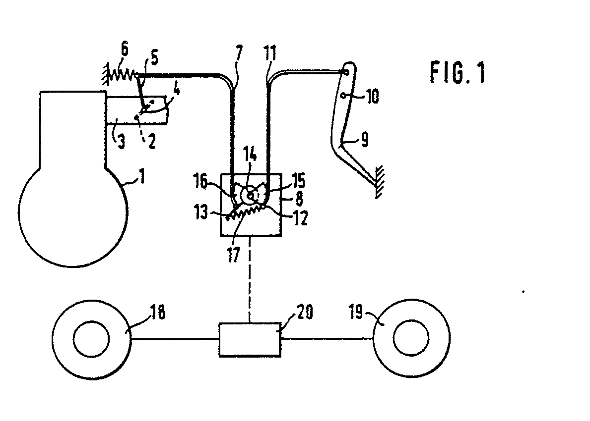
Description
Die Erfindung bezieht sich auf eine Anordnung für eine Brennkraftmaschine zum Eingriff in die Verbindung zwischen einem Bedienorgan und einem die Leistung bestimmenden Steuerorgan, wobei die die Verbindung bildende Einrichtung durch auf das Steuerorgan wirkende Federkräfte unter Zugspannung steht.The invention relates to an arrangement for an internal combustion engine for engaging in the connection between an operating element and a control element determining the power, the device forming the connection being under tension by spring forces acting on the control element.
Für verschiedene Regelungen von Brennkraftmaschinen ist ein Eingriff in die Verbindung zwischen dem Bedienorgan, beispielsweise dem Gaspedal, und dem Steuerorgan, beispielsweise der Drosselklappe oder dem Stellhebel der Einspritzpumpe, erforderlich. Die Regeleinrichtungen können dabei an sich bekannte Einrichtungen zur Vermeidung von Schlupf oder Geschwindigkeitsbegrenzungsregler sein. Der Eingriff hat stets derart zu erfolgen, daß die Regelung nur eine Verringerung der vom Fahrer vorgegebenen Leistung ermöglicht.An intervention in the connection between the operating element, for example the accelerator pedal, and the control element, for example the throttle valve or the actuating lever of the injection pump, is required for various controls of internal combustion engines. The control devices can be devices known per se for avoiding slip or speed limit controllers. The intervention must always be carried out in such a way that the regulation only allows a reduction in the power specified by the driver.
Bei bekannten Anordnungen zum Eingriff in die Verbindung zwischen dem Bedienorgan und dem Steuerorgan einer Brennkraftmaschine sind hydraulische Stellglieder vorgesehen. Diese bedeuten jedoch insbesondere in Personenkraftwagen einen erheblichen Mehraufwand. Bei einer weiteren bekannten Anordnung ist in das Gestänge zwischen dem Gaspedal und der Drosselklappe eines Nutzkraftfahrzeugs ein Hebel eingeschaltet, dessen Drehpunkt bei Einsetzen der Geschwindigkeitsregelung verschoben wird. Dabei ist jedoch eine von der Stellung des Gaspedals abhängige Wirkung zwischen dem Stellglied und dem Steuerorgan vorhanden. Erwünscht ist jedoch eine eindeutige Zuordnung zwischen dem Stellglied und dem Steuerorgan, wenn der Eingriff erfolgt, das heißt, wenn nicht die vorangige Steuerung durch das Gaspedal vorgenommen wird.In known arrangements for engaging in the connection between the control element and the control element of an internal combustion engine, hydraulic actuators are provided. However, these mean considerable additional effort, particularly in passenger cars. In a further known arrangement, a lever is switched into the linkage between the accelerator pedal and the throttle valve of a commercial vehicle, the lever of which is shifted when the cruise control is used. However, there is an effect between the actuator and the control element which is dependent on the position of the accelerator pedal. What is desired, however, is an unambiguous assignment between the actuator and the control element when the intervention takes place, that is to say if the previous control is not carried out by the accelerator pedal.
Diese Aufgabe wird erfindungsgemäß dadurch gelöst, daß das Bedienorgan mit einem ersten Hebel und das Steuerorgan mit einem zweiten Hebel verbunden sind, daß eine Feder zwischen den Hebeln angeordnet ist, deren Kraft im Sinne einer Aufrechterhaltung der Zugspannung wirkt, und daß der zweite Hebel über eine einseitig wirkende Kupplung mit einem Stellglied verbunden ist. Die erfindungsgemäße Anordnung hat den Vorteil, daß ein Eingriff in die Verbindung zwischen dem Bedienorgan und dem Steuerorgan einer Brennkraftmaschine derart erfolgt, daß eine feste Zuordnung zwischen der Stellung des den Eingriff steuernden Stellgliedes und dem Steuerorgan vorhanden ist und daß ohne einen Eingriff eine direkte Betätigung des Steuerorgans mit Hilfe von an sich bekannten Verbindungsmitteln zwischen dem Bedienorgan und dem Steuerorgan (Seilzüge usw.) möglich ist.This object is achieved in that the control element is connected to a first lever and the control element to a second lever, that a spring is arranged between the levers, the force of which acts to maintain the tension, and that the second lever has a single-acting clutch is connected to an actuator. The arrangement according to the invention has the advantage that an intervention in the connection between the control member and the control member of an internal combustion engine takes place in such a way that there is a fixed association between the position of the actuator controlling the engagement and the control member and that, without an intervention, direct actuation of the Control member is possible with the aid of connecting means known per se between the operating member and the control member (cables, etc.).
Eine Weiterbildung der Erfindung besteht darin, daß der erste und der zweite Hebel und ein einen Teil der Anschlagkupplung umfassendes Abtriebselement des Stellgliedes gleichachsig gelagert sind. Damit ist eine einfache, kompakte und kostensparende Bauweise der erfindungsgemäßen Anordnung möglich.A further development of the invention consists in the fact that the first and the second lever and an output element of the actuator comprising a part of the stop coupling are mounted coaxially. A simple, compact and cost-saving design of the arrangement according to the invention is thus possible.
Eine andere Weiterbildung der Erfindung besteht darin, daß die Feder zwischen den Hebeln derart angeordnet ist, daß mit zunehmender Auslenkung der Feder die wirksame Hebellänge kleiner wird. Eine vorteilhafte Ausgestaltung dieser Weiterbildung besteht darin, daß die Hebel in einer Ruhestellung, in welcher vom Stellglied kein Eingriff vorgenommen wird, einen Winkel von etwa 90°, vorzugsweise zwischen 75° und 110°, einschließen. Durch diese Weiterbildung sowie durch die besondere Ausgestaltung wird eine Reduzierung der maximal vom Stellglied aufzubringenden Kraft erreicht.Another development of the invention is that the spring is arranged between the levers in such a way that the effective lever length becomes smaller with increasing deflection of the spring. An advantageous embodiment of this development consists in that the levers enclose an angle of approximately 90 °, preferably between 75 ° and 110 °, in a rest position, in which the actuator does not intervene. This further development and the special configuration reduce the maximum force to be exerted by the actuator.
Zur Sicherstellung einer einwandfreien Übertragung der Bewegung vom Gaspedal auf die Drosselklappe, wenn kein Eingriff erfolgt, ist eine genügend große Zugkraft der zwischen den Hebeln angeordneten Feder erforderlich. Diese Zugkraft ist mindestens um die auftretende Reibung größer als die Rückstellkraft der Feder an der Drosselklappe bei Vollgasstellung. Wird nun aus der Vollgasstellung heraus mit Hilfe des Stellgliedes eine Abregelung vorgenommen, so erfolgt dieses gegen die mit zunehmender Auslenkung größer werdende Kraft der Feder, wobei die diese Bewegung an sich unterstützende Wirkung der Rückstellfeder der Drosselklappe mit zunehmender Abregelung kleiner wird. Durch die Weiterbildung der Erfindung wird erreicht, daß die Wirkung der Zugkraft der Fe der auf die Hebel mit zunehmender Auslenkung geringer wird so daß das Stellglied für kleinere Kräfte bzw. Drehmomente ausgelegt sein kann.In order to ensure that the movement from the accelerator pedal to the throttle valve is transmitted correctly when there is no intervention, a sufficiently large tractive force of the spring arranged between the levers is required. This tensile force is greater than the restoring force of the spring on the throttle valve at full throttle at least by the friction that occurs. If now from the full throttle position with the help of the actuator, a reduction is carried out, this takes place against the increasing force of the spring with increasing deflection, the movement supporting effect of the return spring of the throttle valve becoming smaller with increasing reduction. The development of the invention ensures that the effect of the tensile force of the Fe which on the levers decreases with increasing deflection so that the actuator can be designed for smaller forces or torques.
Eine weitere Verringerung der erforderlichen Kraft bzw. des erforderlichen Drehmoments des Steuerorgans wird durch eine andere Weiterbildung der Erfindung erreicht. Diese ist dadurch gekennzeichnet, daß die Feder einer von der Stellung des Steuerorgans abhängigen Vorspannung unterworfen ist. Diese Weiterbildung nutzt den Zusammenhang zwischen Federweg und Federkraft der Rückstellfeder des Steuerorgans aus und sieht dementsprechend eine starke Federkraft zwischen den Hebeln nur bei einer entsprechend großen Auslenkung des Steuerorgans vor.A further reduction in the required force or the required torque of the control member is achieved by another development of the invention. This is characterized in that the spring is subjected to a bias dependent on the position of the control member. This development takes advantage of the relationship between spring travel and spring force of the return spring of the control member and accordingly provides a strong spring force between the levers only with a correspondingly large deflection of the control member.
Eine vorteilhafte Ausgestaltung dieser Weiterbildung besteht darin, daß die Feder mit dem ersten Hebel über eine auf dem ersten Hebel angeordnete Umlenkrolle verbunden ist, um welche ein Zugseil gelegt ist, welches die Verbindung des einen Endes der Feder mit einem festen Punkt bewirkt. Eine weitere Ausgestaltung besteht darin, daß der Angriffspunkt der Feder an mindestens einem der Hebel in Abhängigkeit von der Stellung des Steuerorgans verschiebbar ist.An advantageous embodiment of this development is that the spring is connected to the first lever via a deflection roller arranged on the first lever, around which a traction cable is placed, which brings about the connection of one end of the spring to a fixed point. A further embodiment consists in that the point of application of the spring on at least one of the levers is displaceable depending on the position of the control member.
Die Erfindung läßt zahlreiche Ausführungsformen zu. Zwei davon sind schematisch in der Zeichnung an Hand mehrerer Figuren dargestellt und nachfolgend beschrieben. Es zeigt:
- Fig. 1 schematisch die Kraftübertragung zwischen einem Gaspedal und der Drosselklappe eines Verbrennungsmotors mit einer erfindungsgemäßen Anordnung,
- Fig. 2 ein Ausführungsbeispiel für eine erfindungsgemäße Anordnung,
- Fig. 3 schematisch eine erfindungsgemäße Anordnung gemäß einer Weiterbildung der Erfindung und
- Fig. 4 schematisch eine andere Ausgestaltung zur Erzielung einer von der Stellung des Steuerorgans abhängigen Vorspannung.
- 1 schematically shows the power transmission between an accelerator pedal and the throttle valve of an internal combustion engine with an arrangement according to the invention,
- 2 shows an embodiment for an arrangement according to the invention,
- Fig. 3 shows schematically an arrangement according to the invention according to a development of the invention and
- Fig. 4 schematically shows another embodiment for achieving a bias dependent on the position of the control member.
Gleiche Teile sind in den Figuren mit gleichen Bezugszeichen versehen.Identical parts are provided with the same reference symbols in the figures.
Bei der Anordnung nach Anspruch 1 wird eine Brennkraftmaschine 1 mit Hilfe einer Drosselklappe 2, welche im Ansaugkanal 3 angeordnet ist, in ihrer Leistung gesteuert. Die Drosselklappe 2 ist um eine Drehachse 4 drehbar angeordnet und wird mit einem Hebel 5 betätigt. Am Ende des Hebels 5 befindet sich einerseits eine Rückstellfeder 6 und andererseits ein Seilzug 7, welcher zur Anordnung 8 führt.In the arrangement according to claim 1, an internal combustion engine 1 is controlled in terms of its output with the aid of a throttle valve 2, which is arranged in the intake duct 3. The throttle valve 2 is rotatably arranged about an axis of rotation 4 and is actuated with a
Die Drosselklappe 2 wird mit Hilfe eines Gaspedals 9 eingestellt, welches um eine Drehachse 10 gelagert ist und über einen weiteren Seilzug 11 mit der Anordnung 8 verbunden ist.The throttle valve 2 is adjusted with the aid of an
Die Seilzüge 7, 11 sind in der Anordnung 8 jeweils mit einem Hebel 12, 13 verbunden, welche unabhängig voneinander drehbar bei 14 gelagert sind. Aus konstruktiven Gründen, unter anderem damit eine Führung des Seilzuges unabhängig von der Winkelstellung der Hebel 12, 13 möglich ist, sind die Hebel mit Seilführungssektoren 15, 16 versehen. Die Hebel 12, 13 sind durch eine Feder 17 miteinander verbunden, deren Kraft größer ist als die Rückstellkraft der Feder 6 und die im Bereich der Drosselklappenanordnung und des Seilzuges 7 auftretende Reibungskraft. Dadurch wird gewährleistet, daß sich ohne den im folgenden beschriebenen Eingriff die Bewegung des Gaspedals störungsfrei auf die Drosselklappe überträgt.The
In Fig. 1 ist ferner eine Einrichtung zur Schlupfregelung angedeutet, welche jeweils von den Vorderrädern 18 und den Hinterrädern 19 ein Drehzahlsignal abnimmt und diese miteinander vergleicht. Weisen die jeweils angetriebenen Räder eine erhöhte Drehzahl auf, so wird von der Einrichtung 20 ein Signal an ein in Fig. 1 nicht dargestelltes Stellglied in der Anordnung 8 gegeben, welches eine Verminderung der Leistung der Brennkraftmaschine 1 verursacht. Dazu wird der Hebel 13 im Uhrzeigersinn gedreht, wodurch die Drosselklappe 2 in Richtung auf die Schließstellung bewegt wird. Dabei wird die Feder 17 gespannt, sofern nicht der Fahrer den Fuß vom Gaspedal 9 nimmt.A device for slip control is also indicated in FIG. 1, which detects a speed signal from the
Bei der in Fig. 2 dargestellten Anordnung sind die Hebel 12 und 13 auf einer gemeinsamen Achse 14 gelagert. Die Teile 15 und 16 der Hebel 12 und 13 bilden Führungselemente für die Seilzüge 7 und 11 (Fig. 1). Die Seilzüge sind in Fig. 2 lediglich durch Pfeile 7, 11 angedeutet. Die sektorförmigen Führungsteile und 16 sind an ihrem Umfang mit einer Nut zur Aufnahme der Seilzuge 7 und 11 vorgesehen. Die zum Umfang hin offenen Bohrungen 21 und 22 dienen zur Aufnahme von das Ende der Seilzüge 7, 11 bildenden walzenförmigen Körpern.In the arrangement shown in Fig. 2, the
Die Enden der Hebel 12 und 13 sind jeweils mit einem Bolzen 23 zur Aufnahme der Feder 17 versehen. Die Feder ist vorgespannt und versucht die Hebel derart gegeneinander zu verdrehen, daß der von ihnen eingeschlossene Winkel kleiner wird. Letzterer ist jedoch durch einen Stift 25 im Hebel 12, welcher einen Anschlag für den Hebel 13 bildet, begrenzt.The ends of the
Die Kraft der Feder 17 ist derart groß, daß sie bei der normalen Bewegung des Gaspedals, das heißt ohne Eingriff in die Verbindung zwischen dem Gaspedal und der Drosselklappe, nicht ausgelenkt wird. Die Bewegung des Gaspedals und damit des Seilzuges 11 wird somit ohne Beeinflussung auf den Seilzug 7 und die Drosselklappe 4 übertragen.The force of the
Zur Vornahme des Eingriffs ist ein an sich bekanntes Stellglied 26 vorgesehen, das beispielsweise von einem Elektromotor und einem Untersetzungsgetriebe gebildet wird. Der Abtrieb des Untersetzungsgetriebes ist gleichachsig mit den Hebeln 12 und 13 angeordnet und besteht aus einem weiteren Hebel 27, welcher an seinem Ende 28 als Anschlag ausgebildet ist und mit der Fläche 29 des Hebels 13 eine Anschlagkupplung darstellt. Der Hebel 27 und damit das Stellglied 26 kann dementsprechend ein Drehmoment auf den Hebel 13 nur im Sinne einer Linksdrehung übertragen. Dieses entspricht einer Verminderung der Leistung der Brennkraftmaschine. Dabei wird die Feder 17 ausgelenkt und die Feder 6 an der Drosselklappenanordnung entlastet. Damit die vom Stellglied aufzubringende Kraft mit zunehmender Auslenkung nicht zu groß wird, sind die Hebel 12, 13 derart ausgebildet, daß mit zunehmender Auslenkung die wirksame Hebellänge aufgrund des größer werdenden Winkels zwischen den Hebeln kleiner wird.To perform the intervention, an
Zu einer weiteren Verringerung des vom Stellglied aufzubringenden Drehmoments tragen Anordnungen nach den Figuren 3 und 4 bei. Dabei wird erreicht, daß die Feder einer von der Stellung der Drosselklappe abhängigen Vorspannung unterworfen ist.Arrangements according to FIGS. 3 and 4 contribute to a further reduction in the torque to be applied by the actuator. It is thereby achieved that the spring is subjected to a prestress dependent on the position of the throttle valve.
Bei der Anordnung nach Figur 3 wird die Länge des Hebels 12 durch eine Kulissenführung 30 mit zunehmender Gaspedalbewegung verlängert. Fig. 3a zeigt die Anordnung in der Leerlaufstellung. Dabei ist das eine Ende der Feder 17 an einem festen Punkt 24 des Hebels 13 angeschlossen, während das andere Ende der Feder 17 am Hebel 12 in einem beweglichen Punkt 31 angeordnet ist. Der Punkt 31 ist in radialer Richtung innerhalb des Hebels 12 beweglich, wozu eine entsprechende Führung 30 im Hebel 12 vorgesehen ist. Ein Führungshebel 32 ist um einen festen Punkt 33 drehbar und bestimmt mit seinem nicht festgelegten Ende die Stellung des Befestigungspunktes 31 für die Feder 17 im Hebel 12. Bei 34 ist schematisch ein Anschlag angedeutet, der verhindert, daß die Feder 17 die Hebel zu einem kleineren Winkel als 90° zusammenzieht.In the arrangement according to FIG. 3, the length of the
Bei der in Fig. 3a gezeigten Leerlaufstellung weist der Befestigungspunkt 31 den kleinsten Radius zum Drehpunkt 14 auf. Die Feder 17 hat daher eine geringe Vorspannung, die jedoch genügt, um bei Bewegung des Gaspedals aus der Leerlaufstellung heraus die Kraft der Rückstellfeder 6 des Drosselklappenhebels zu überwinden.In the idle position shown in FIG. 3a, the
Die Figuren 3b und 3c zeigen die gleiche Anordnung wie in Fig. 3a, jedoch in Fig. 3c in der Vollgasstellung und in Fig. 3b in einer Mittelstellung.Figures 3b and 3c show the same arrangement as in Fig. 3a, but in Fig. 3c in the full throttle position and in Fig. 3b in a central position.
Gegenüber der in Fig. 3a gezeigten Stellung ist bei der Mittelstellung (Fig. 3b) der Befestigungspunkt 31 der Feder 17 etwas weiter vom Drehpunkt 14 entfernt, so daß die Feder 17 stärker gespannt ist. Bei Fig. 3c hat der Führungshebel 32 den Befestigungspunkt 31 an das äußere Ende der Führung 30 geschoben, wodurch die Feder am stärksten gespannt ist.Compared to the position shown in FIG. 3a, in the middle position (FIG. 3b) the
Bei der in Fig. 4 dargestellten Anordnung wird eine stellungsabhängige Vorspannung der Feder dadurch erreicht, daß auf dem Hebel 12 anstelle eines Befestigungspunktes eine Umlenkrolle 35 vorgesehen ist. Über die Umlenkrolle 35 läuft ein Seil 36, welches mit einem Ende an der Feder 17 und mit dem anderen Ende an einem festen Punkt 37 befestigt ist. Bei der in Fig. 4a gezeigten Leerlaufstellung ist die Entfernung zwischen der Umlenkrolle 35 und dem festen Punkt 37 klein, so daß der größere Teil des Seils 36 zwischen der Umlenkrolle 35 und der Feder 17 ist, so daß die Feder 17 nur geringfügig gespannt ist. Mit zunehmender Auslenkung wird die Feder stärker gespannt, so daß bei Vollgasstellung (Fig. 4b) die größte Vorspannung erreicht wird.In the arrangement shown in Fig. 4, a position-dependent bias of the spring is achieved in that a deflecting
Claims (8)
daß das Bedienorgan (9) mit einem ersten Hebel (12) und das Steuerorgan (2) mit einem zweiten Hebel (13) verbunden sind,
daß eine Feder (17) zwischen den Hebeln (12, 13) angeordnet ist, deren Kraft im Sinne einer Aufrechterhaltung der Zugspannung wirkt,
und daß der zweite Hebel (13) über eine einseitig wirkende Kupplung (28, 29) mit einem Stellglied (26) verbunden ist.1. Arrangement for engaging in the connection between an operating element and a control element determining the performance of an internal combustion engine, the device forming the connection being under tension by spring forces acting on the control element, characterized in that
that the control element (9) is connected to a first lever (12) and the control element (2) is connected to a second lever (13),
that a spring (17) is arranged between the levers (12, 13), the force of which acts in the sense of maintaining the tension,
and that the second lever (13) is connected to an actuator (26) via a one-way coupling (28, 29).
Applications Claiming Priority (2)
| Application Number | Priority Date | Filing Date | Title |
|---|---|---|---|
| DE3601622 | 1986-01-21 | ||
| DE19863601622 DE3601622A1 (en) | 1986-01-21 | 1986-01-21 | ARRANGEMENT FOR AN INTERNAL COMBUSTION ENGINE |
Publications (2)
| Publication Number | Publication Date |
|---|---|
| EP0230516A2 true EP0230516A2 (en) | 1987-08-05 |
| EP0230516A3 EP0230516A3 (en) | 1989-01-25 |
Family
ID=6292274
Family Applications (1)
| Application Number | Title | Priority Date | Filing Date |
|---|---|---|---|
| EP86113488A Withdrawn EP0230516A3 (en) | 1986-01-21 | 1986-10-01 | Device for positioning the power control element of an internal-combustion engine |
Country Status (4)
| Country | Link |
|---|---|
| EP (1) | EP0230516A3 (en) |
| JP (1) | JPS62170740A (en) |
| BR (1) | BR8700218A (en) |
| DE (1) | DE3601622A1 (en) |
Cited By (4)
| Publication number | Priority date | Publication date | Assignee | Title |
|---|---|---|---|---|
| FR2619059A1 (en) * | 1987-08-07 | 1989-02-10 | Bendix France | Device for preventing a loss of grip of the driving wheels of a vehicle during acceleration |
| DE3831257A1 (en) * | 1987-09-14 | 1989-03-23 | Mazda Motor | DEVICE FOR CONTROLLING THE OPENING DEGREE OF A THROTTLE VALVE ON A VEHICLE ENGINE |
| EP0391367B1 (en) * | 1989-04-04 | 1994-06-22 | Fuji Jukogyo Kabushiki Kaisha | Device for controlling speed of an engine |
| WO1994029138A1 (en) * | 1993-06-09 | 1994-12-22 | Automotive Products Plc | Fuel supply control |
Families Citing this family (4)
| Publication number | Priority date | Publication date | Assignee | Title |
|---|---|---|---|---|
| DE3628538C2 (en) * | 1986-08-22 | 1995-05-18 | Vdo Schindling | Arrangement for a motor vehicle for engaging in the connection between an operating element and a control element which determines the output of the internal combustion engine of the motor vehicle |
| JPH03114969A (en) * | 1989-09-28 | 1991-05-16 | Mazda Motor Corp | Slip control device for vehicle |
| DE4010591A1 (en) * | 1990-04-02 | 1991-10-10 | Rolf Weigele | Energy control pedal for motor vehicle engine - has spring providing increased resistance to movement indicating increasing power level |
| JPH0444449U (en) * | 1990-08-21 | 1992-04-15 |
Family Cites Families (3)
| Publication number | Priority date | Publication date | Assignee | Title |
|---|---|---|---|---|
| DE1094113B (en) * | 1959-07-31 | 1960-12-01 | Daimler Benz Ag | Device for the automatic control of the throttle element of a vehicle internal combustion engine |
| JPS57172828A (en) * | 1981-04-15 | 1982-10-23 | Nissan Motor Co Ltd | Acceleration controller for car equipped with constant-speed travelling apparatus |
| JPS58210336A (en) * | 1982-05-31 | 1983-12-07 | Fuji Heavy Ind Ltd | Interlocking operation unit for control wire |
-
1986
- 1986-01-21 DE DE19863601622 patent/DE3601622A1/en not_active Withdrawn
- 1986-10-01 EP EP86113488A patent/EP0230516A3/en not_active Withdrawn
-
1987
- 1987-01-20 JP JP62009206A patent/JPS62170740A/en active Pending
- 1987-01-20 BR BR8700218A patent/BR8700218A/en unknown
Cited By (6)
| Publication number | Priority date | Publication date | Assignee | Title |
|---|---|---|---|---|
| FR2619059A1 (en) * | 1987-08-07 | 1989-02-10 | Bendix France | Device for preventing a loss of grip of the driving wheels of a vehicle during acceleration |
| DE3831257A1 (en) * | 1987-09-14 | 1989-03-23 | Mazda Motor | DEVICE FOR CONTROLLING THE OPENING DEGREE OF A THROTTLE VALVE ON A VEHICLE ENGINE |
| EP0391367B1 (en) * | 1989-04-04 | 1994-06-22 | Fuji Jukogyo Kabushiki Kaisha | Device for controlling speed of an engine |
| WO1994029138A1 (en) * | 1993-06-09 | 1994-12-22 | Automotive Products Plc | Fuel supply control |
| GB2284019A (en) * | 1993-06-09 | 1995-05-24 | Automotive Products Plc | Fuel supply control |
| GB2284019B (en) * | 1993-06-09 | 1996-06-26 | Automotive Products Plc | Fuel supply control |
Also Published As
| Publication number | Publication date |
|---|---|
| DE3601622A1 (en) | 1987-07-23 |
| BR8700218A (en) | 1987-12-01 |
| EP0230516A3 (en) | 1989-01-25 |
| JPS62170740A (en) | 1987-07-27 |
Similar Documents
| Publication | Publication Date | Title |
|---|---|---|
| DE19524941B4 (en) | load adjusting | |
| EP0373368A1 (en) | Device for locking a gear shift lever in a particular gear or range position, depending on a brake pedal | |
| WO2008046563A1 (en) | Valve device | |
| DE10297538B4 (en) | Pedal with direct force feedback | |
| DE10212879A1 (en) | Actuation mechanism for a parking brake | |
| DE3936875A1 (en) | THROTTLE VALVE FOR AN INTERNAL COMBUSTION ENGINE | |
| EP0230516A2 (en) | Device for positioning the power control element of an internal-combustion engine | |
| DE10297549T5 (en) | Force feedback mechanism | |
| DE102016214774B4 (en) | Rotary drive device with load-dependent brake | |
| EP0359990B1 (en) | Stepper motor device for engagement in a transfer device | |
| DE19848584B4 (en) | Self-energizing friction clutch | |
| EP0810359B1 (en) | Load control device | |
| DE8602379U1 (en) | Propulsion control device for motor vehicles | |
| DE68904644T2 (en) | THROTTLE VALVE CONTROL DEVICE FOR AN INTERNAL COMBUSTION ENGINE. | |
| DE202019100595U1 (en) | Braking device | |
| EP0369178A2 (en) | Device to influence the position of a command organ of a combustion engine | |
| DE10211297A1 (en) | Actuator for automated transmissions | |
| DE10222842B3 (en) | Cruise control device for motor vehicle, has cord reel with two side walls for forming groove to accommodate pulling cord whose ends are coupled to reel and speed control mechanism | |
| EP0989293B1 (en) | Load control device | |
| DE19519836C2 (en) | Load adjustment device | |
| DE102018221801A1 (en) | Parking lock arrangement, transmission and motor vehicle | |
| DE602004013415T2 (en) | External switching device for driving a commercial vehicle | |
| DE3744420C2 (en) | Control device for a hydrostatic transmission driven by an internal combustion engine | |
| DE69508900T2 (en) | Pedal actuation device for controlling the Bowden cable of the throttle valve of a fuel supply device for an internal combustion engine | |
| DE10238704B4 (en) | Actuating device of an adjusting device for motor vehicle seats |
Legal Events
| Date | Code | Title | Description |
|---|---|---|---|
| PUAI | Public reference made under article 153(3) epc to a published international application that has entered the european phase |
Free format text: ORIGINAL CODE: 0009012 |
|
| AK | Designated contracting states |
Kind code of ref document: A2 Designated state(s): DE FR GB IT SE |
|
| PUAL | Search report despatched |
Free format text: ORIGINAL CODE: 0009013 |
|
| AK | Designated contracting states |
Kind code of ref document: A3 Designated state(s): DE FR GB IT SE |
|
| STAA | Information on the status of an ep patent application or granted ep patent |
Free format text: STATUS: THE APPLICATION IS DEEMED TO BE WITHDRAWN |
|
| 18D | Application deemed to be withdrawn |
Effective date: 19890726 |
|
| RIN1 | Information on inventor provided before grant (corrected) |
Inventor name: HANNEWALD, THOMAS Inventor name: WIETSCHORKE-MUHSOLD, STEPHAN Inventor name: HICKMANN, GERD Inventor name: SCHNEIDER, ERWIN |