EP0230516A2 - Dispositif de commande de l'organe de réglage de la puissance d'un moteur à combustion interne - Google Patents
Dispositif de commande de l'organe de réglage de la puissance d'un moteur à combustion interne Download PDFInfo
- Publication number
- EP0230516A2 EP0230516A2 EP86113488A EP86113488A EP0230516A2 EP 0230516 A2 EP0230516 A2 EP 0230516A2 EP 86113488 A EP86113488 A EP 86113488A EP 86113488 A EP86113488 A EP 86113488A EP 0230516 A2 EP0230516 A2 EP 0230516A2
- Authority
- EP
- European Patent Office
- Prior art keywords
- spring
- lever
- levers
- arrangement according
- control element
- Prior art date
- Legal status (The legal status is an assumption and is not a legal conclusion. Google has not performed a legal analysis and makes no representation as to the accuracy of the status listed.)
- Withdrawn
Links
Images
Classifications
-
- F—MECHANICAL ENGINEERING; LIGHTING; HEATING; WEAPONS; BLASTING
- F02—COMBUSTION ENGINES; HOT-GAS OR COMBUSTION-PRODUCT ENGINE PLANTS
- F02D—CONTROLLING COMBUSTION ENGINES
- F02D9/00—Controlling engines by throttling air or fuel-and-air induction conduits or exhaust conduits
- F02D9/02—Controlling engines by throttling air or fuel-and-air induction conduits or exhaust conduits concerning induction conduits
-
- B—PERFORMING OPERATIONS; TRANSPORTING
- B60—VEHICLES IN GENERAL
- B60K—ARRANGEMENT OR MOUNTING OF PROPULSION UNITS OR OF TRANSMISSIONS IN VEHICLES; ARRANGEMENT OR MOUNTING OF PLURAL DIVERSE PRIME-MOVERS IN VEHICLES; AUXILIARY DRIVES FOR VEHICLES; INSTRUMENTATION OR DASHBOARDS FOR VEHICLES; ARRANGEMENTS IN CONNECTION WITH COOLING, AIR INTAKE, GAS EXHAUST OR FUEL SUPPLY OF PROPULSION UNITS IN VEHICLES
- B60K28/00—Safety devices for propulsion-unit control, specially adapted for, or arranged in, vehicles, e.g. preventing fuel supply or ignition in the event of potentially dangerous conditions
- B60K28/10—Safety devices for propulsion-unit control, specially adapted for, or arranged in, vehicles, e.g. preventing fuel supply or ignition in the event of potentially dangerous conditions responsive to conditions relating to the vehicle
- B60K28/16—Safety devices for propulsion-unit control, specially adapted for, or arranged in, vehicles, e.g. preventing fuel supply or ignition in the event of potentially dangerous conditions responsive to conditions relating to the vehicle responsive to, or preventing, spinning or skidding of wheels
-
- F—MECHANICAL ENGINEERING; LIGHTING; HEATING; WEAPONS; BLASTING
- F02—COMBUSTION ENGINES; HOT-GAS OR COMBUSTION-PRODUCT ENGINE PLANTS
- F02D—CONTROLLING COMBUSTION ENGINES
- F02D9/00—Controlling engines by throttling air or fuel-and-air induction conduits or exhaust conduits
- F02D9/02—Controlling engines by throttling air or fuel-and-air induction conduits or exhaust conduits concerning induction conduits
- F02D2009/0201—Arrangements; Control features; Details thereof
- F02D2009/0255—Arrangements; Control features; Details thereof with means for correcting throttle position, e.g. throttle cable of variable length
Definitions
- the invention relates to an arrangement for an internal combustion engine for engaging in the connection between an operating element and a control element determining the power, the device forming the connection being under tension by spring forces acting on the control element.
- An intervention in the connection between the operating element, for example the accelerator pedal, and the control element, for example the throttle valve or the actuating lever of the injection pump, is required for various controls of internal combustion engines.
- the control devices can be devices known per se for avoiding slip or speed limit controllers.
- the intervention must always be carried out in such a way that the regulation only allows a reduction in the power specified by the driver.
- control element is connected to a first lever and the control element to a second lever, that a spring is arranged between the levers, the force of which acts to maintain the tension, and that the second lever has a single-acting clutch is connected to an actuator.
- the arrangement according to the invention has the advantage that an intervention in the connection between the control member and the control member of an internal combustion engine takes place in such a way that there is a fixed association between the position of the actuator controlling the engagement and the control member and that, without an intervention, direct actuation of the Control member is possible with the aid of connecting means known per se between the operating member and the control member (cables, etc.).
- a further development of the invention consists in the fact that the first and the second lever and an output element of the actuator comprising a part of the stop coupling are mounted coaxially. A simple, compact and cost-saving design of the arrangement according to the invention is thus possible.
- the spring is arranged between the levers in such a way that the effective lever length becomes smaller with increasing deflection of the spring.
- An advantageous embodiment of this development consists in that the levers enclose an angle of approximately 90 °, preferably between 75 ° and 110 °, in a rest position, in which the actuator does not intervene. This further development and the special configuration reduce the maximum force to be exerted by the actuator.
- a further reduction in the required force or the required torque of the control member is achieved by another development of the invention.
- This is characterized in that the spring is subjected to a bias dependent on the position of the control member.
- the spring is connected to the first lever via a deflection roller arranged on the first lever, around which a traction cable is placed, which brings about the connection of one end of the spring to a fixed point.
- a further embodiment consists in that the point of application of the spring on at least one of the levers is displaceable depending on the position of the control member.
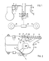
- an internal combustion engine 1 is controlled in terms of its output with the aid of a throttle valve 2, which is arranged in the intake duct 3.
- the throttle valve 2 is rotatably arranged about an axis of rotation 4 and is actuated with a lever 5.
- a return spring 6 At the end of the lever 5 there is on the one hand a return spring 6 and on the other hand a cable 7 which leads to the arrangement 8.
- the throttle valve 2 is adjusted with the aid of an accelerator pedal 9, which is mounted about an axis of rotation 10 and is connected to the arrangement 8 via a further cable 11.
- the cables 7, 11 are each connected to a lever 12, 13 in the arrangement 8, which are rotatably supported at 14 independently of one another.
- the levers are provided with cable guide sectors 15, 16.
- the levers 12, 13 are connected to one another by a spring 17, the force of which is greater than the restoring force of the spring 6 and the frictional force occurring in the area of the throttle valve arrangement and the cable 7. This ensures that the movement of the accelerator pedal is transmitted to the throttle valve without interference without the intervention described below.
- a device for slip control is also indicated in FIG. 1, which detects a speed signal from the front wheels 18 and the rear wheels 19 and compares them with one another. If the driven wheels have an increased speed, the device 20 sends a signal to an actuator (not shown in FIG. 1) in the arrangement 8, which causes a reduction in the power of the internal combustion engine 1.
- the lever 13 is rotated clockwise, whereby the throttle valve 2 is moved in the direction of the closed position.
- the spring 17 is tensioned unless the driver takes his foot off the accelerator pedal 9.
- the levers 12 and 13 are mounted on a common axis 14.
- the parts 15 and 16 of the levers 12 and 13 form guide elements for the cables 7 and 11 (Fig. 1).
- the cables are in Fig. 2 only by arrows 7, 11 indicated.
- the sector-shaped guide parts 16 and 16 are provided on their circumference with a groove for receiving the cables 7 and 11.
- the holes 21 and 22, which are open towards the circumference, serve to receive roller-shaped bodies forming the end of the cables 7, 11.
- the ends of the levers 12 and 13 are each provided with a bolt 23 for receiving the spring 17.
- the spring is biased and tries to turn the levers against each other in such a way that the angle they enclose becomes smaller. However, the latter is limited by a pin 25 in the lever 12, which forms a stop for the lever 13.
- the force of the spring 17 is so great that it is not deflected during the normal movement of the accelerator pedal, that is to say without intervention in the connection between the accelerator pedal and the throttle valve.
- the movement of the accelerator pedal and thus of the cable 11 is thus transmitted to the cable 7 and the throttle valve 4 without being influenced.
- an actuator 26 known per se is provided, which is formed, for example, by an electric motor and a reduction gear.
- the output of the reduction gear is arranged coaxially with the levers 12 and 13 and consists of a further lever 27, which is designed as a stop at its end 28 and represents a stop coupling with the surface 29 of the lever 13.
- the lever 27 and thus the actuator 26 can accordingly transmit a torque to the lever 13 only in the sense of a left turn. This corresponds to a reduction in performance the internal combustion engine.
- the spring 17 is deflected and the spring 6 on the throttle valve assembly is relieved. So that the force to be applied by the actuator does not become too great as the deflection increases, the levers 12, 13 are designed such that the effective lever length becomes smaller as the deflection increases due to the increasing angle between the levers.
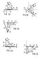
- FIGS. 3 and 4 contribute to a further reduction in the torque to be applied by the actuator. It is thereby achieved that the spring is subjected to a prestress dependent on the position of the throttle valve.
- the length of the lever 12 is extended by a link guide 30 with increasing accelerator pedal movement.
- 3a shows the arrangement in the idle position.
- One end of the spring 17 is connected to a fixed point 24 of the lever 13, while the other end of the spring 17 is arranged on the lever 12 in a movable point 31.
- the point 31 is movable in the radial direction within the lever 12, for which purpose a corresponding guide 30 is provided in the lever 12.
- a guide lever 32 is rotatable about a fixed point 33 and determines with its unspecified end the position of the fastening point 31 for the spring 17 in the lever 12.
- a stop is schematically indicated, which prevents the spring 17 from reducing the lever to a smaller one Angle contracts as 90 °.
- the attachment point 31 has the smallest radius to the pivot point 14.
- the spring 17 therefore has a slight pretension, which, however, is sufficient to overcome the force of the return spring 6 of the throttle valve lever when the accelerator pedal is moved from the idle position.
- Figures 3b and 3c show the same arrangement as in Fig. 3a, but in Fig. 3c in the full throttle position and in Fig. 3b in a central position.
- a position-dependent bias of the spring is achieved in that a deflecting roller 35 is provided on the lever 12 instead of a fastening point.
- a cable 36 runs over the deflection roller 35 and is fastened at one end to the spring 17 and at the other end to a fixed point 37.
- the distance between the deflection roller 35 and the fixed point 37 is small, so that the greater part of the rope 36 between the deflection roller 35 and the spring 17, so that the spring 17 is only slightly tensioned.
- the spring is tensioned more so that the greatest pretension is achieved when the throttle is at full throttle (FIG. 4b).
Landscapes
- Engineering & Computer Science (AREA)
- Chemical & Material Sciences (AREA)
- Combustion & Propulsion (AREA)
- Mechanical Engineering (AREA)
- Transportation (AREA)
- General Engineering & Computer Science (AREA)
- Control Of Throttle Valves Provided In The Intake System Or In The Exhaust System (AREA)
- Mechanical Control Devices (AREA)
Applications Claiming Priority (2)
| Application Number | Priority Date | Filing Date | Title |
|---|---|---|---|
| DE3601622 | 1986-01-21 | ||
| DE19863601622 DE3601622A1 (de) | 1986-01-21 | 1986-01-21 | Anordnung fuer eine brennkraftmaschine |
Publications (2)
| Publication Number | Publication Date |
|---|---|
| EP0230516A2 true EP0230516A2 (fr) | 1987-08-05 |
| EP0230516A3 EP0230516A3 (fr) | 1989-01-25 |
Family
ID=6292274
Family Applications (1)
| Application Number | Title | Priority Date | Filing Date |
|---|---|---|---|
| EP86113488A Withdrawn EP0230516A3 (fr) | 1986-01-21 | 1986-10-01 | Dispositif de commande de l'organe de réglage de la puissance d'un moteur à combustion interne |
Country Status (4)
| Country | Link |
|---|---|
| EP (1) | EP0230516A3 (fr) |
| JP (1) | JPS62170740A (fr) |
| BR (1) | BR8700218A (fr) |
| DE (1) | DE3601622A1 (fr) |
Cited By (4)
| Publication number | Priority date | Publication date | Assignee | Title |
|---|---|---|---|---|
| FR2619059A1 (fr) * | 1987-08-07 | 1989-02-10 | Bendix France | Dispositif pour empecher une perte d'adherence des roues motrices d'un vehicule lors d'une acceleration |
| DE3831257A1 (de) * | 1987-09-14 | 1989-03-23 | Mazda Motor | Einrichtung zur steuerung des oeffnungsgrades eines drosselventils an einem fahrzeugmotor |
| EP0391367B1 (fr) * | 1989-04-04 | 1994-06-22 | Fuji Jukogyo Kabushiki Kaisha | Dispositif pour régler la vitesse d'un moteur |
| WO1994029138A1 (fr) * | 1993-06-09 | 1994-12-22 | Automotive Products Plc | Commande de l'alimentation du carburant |
Families Citing this family (4)
| Publication number | Priority date | Publication date | Assignee | Title |
|---|---|---|---|---|
| DE3628538C2 (de) * | 1986-08-22 | 1995-05-18 | Vdo Schindling | Anordnung für ein Kraftfahrzeug zum Eingriff in die Verbindung zwischen einem Bedienorgan und einem die Leistung der Brennkraftmaschine des Kraftfahrzeugs bestimmenden Steuerorgan |
| JPH03114969A (ja) * | 1989-09-28 | 1991-05-16 | Mazda Motor Corp | 車両のスリップ制御装置 |
| DE4010591A1 (de) * | 1990-04-02 | 1991-10-10 | Rolf Weigele | Energieverbrauchssteuereinheit (evse) |
| JPH0444449U (fr) * | 1990-08-21 | 1992-04-15 |
Family Cites Families (3)
| Publication number | Priority date | Publication date | Assignee | Title |
|---|---|---|---|---|
| DE1094113B (de) * | 1959-07-31 | 1960-12-01 | Daimler Benz Ag | Einrichtung zum selbsttaetigen Regeln des Drosselgliedes einer Fahrzeugbrennkraftmaschine |
| JPS57172828A (en) * | 1981-04-15 | 1982-10-23 | Nissan Motor Co Ltd | Acceleration controller for car equipped with constant-speed travelling apparatus |
| JPS58210336A (ja) * | 1982-05-31 | 1983-12-07 | Fuji Heavy Ind Ltd | 制御索の連動操作装置 |
-
1986
- 1986-01-21 DE DE19863601622 patent/DE3601622A1/de not_active Withdrawn
- 1986-10-01 EP EP86113488A patent/EP0230516A3/fr not_active Withdrawn
-
1987
- 1987-01-20 JP JP62009206A patent/JPS62170740A/ja active Pending
- 1987-01-20 BR BR8700218A patent/BR8700218A/pt unknown
Cited By (6)
| Publication number | Priority date | Publication date | Assignee | Title |
|---|---|---|---|---|
| FR2619059A1 (fr) * | 1987-08-07 | 1989-02-10 | Bendix France | Dispositif pour empecher une perte d'adherence des roues motrices d'un vehicule lors d'une acceleration |
| DE3831257A1 (de) * | 1987-09-14 | 1989-03-23 | Mazda Motor | Einrichtung zur steuerung des oeffnungsgrades eines drosselventils an einem fahrzeugmotor |
| EP0391367B1 (fr) * | 1989-04-04 | 1994-06-22 | Fuji Jukogyo Kabushiki Kaisha | Dispositif pour régler la vitesse d'un moteur |
| WO1994029138A1 (fr) * | 1993-06-09 | 1994-12-22 | Automotive Products Plc | Commande de l'alimentation du carburant |
| GB2284019A (en) * | 1993-06-09 | 1995-05-24 | Automotive Products Plc | Fuel supply control |
| GB2284019B (en) * | 1993-06-09 | 1996-06-26 | Automotive Products Plc | Fuel supply control |
Also Published As
| Publication number | Publication date |
|---|---|
| DE3601622A1 (de) | 1987-07-23 |
| BR8700218A (pt) | 1987-12-01 |
| EP0230516A3 (fr) | 1989-01-25 |
| JPS62170740A (ja) | 1987-07-27 |
Similar Documents
| Publication | Publication Date | Title |
|---|---|---|
| DE19524941B4 (de) | Lastverstellvorrichtung | |
| EP0373368A1 (fr) | Dispositif pour verrouiller un levier de changement de vitesse dans une position correspondant à un rapport ou d'une programmation de rapports dépendant d'une pédale de frein | |
| WO2008046563A1 (fr) | Dispositif soupape | |
| DE10297538B4 (de) | Pedal mit unmittelbarer Kraftrückkopplung | |
| DE10212879A1 (de) | Betätigungsmechanismus für eine Feststellbremse | |
| DE3936875A1 (de) | Drosselklappe fuer eine brennkraftmaschine | |
| EP0230516A2 (fr) | Dispositif de commande de l'organe de réglage de la puissance d'un moteur à combustion interne | |
| DE10297549T5 (de) | Kraftrückkopplungsmechanismus | |
| DE102016214774B4 (de) | Drehantriebseinrichtung mit lastabhängiger Bremse | |
| EP0359990B1 (fr) | Dispositif avec moteur de réglage pour l'intervention dans un mécanisme de transfert | |
| DE19848584B4 (de) | Selbstverstärkende Reibungskupplung | |
| EP0810359B1 (fr) | Dispositif de commande de charge | |
| DE8602379U1 (de) | Vorrichtung zur Vortriebsregelung für Kraftfahrzeuge | |
| DE68904644T2 (de) | Drosselklappenkontrolleinrichtung fuer einen verbrennungsmotor. | |
| DE202019100595U1 (de) | Bremseinrichtung | |
| EP0369178A2 (fr) | Installation pour influencer la position d'un organe de commande d'un moteur à combustion | |
| DE10211297A1 (de) | Stellvorrichtung für automatisiertes Getriebe | |
| DE10222842B3 (de) | Geschwindigkeits-Regeleinrichtung für ein Kraftfahrzeug | |
| EP0989293B1 (fr) | Dispositif de commande de charge | |
| DE19519836C2 (de) | Lastverstelleinrichtung | |
| DE102018221801A1 (de) | Parksperrenanordnung, Getriebe sowie Kraftfahrzeug | |
| DE602004013415T2 (de) | Externe Schaltvorrichtung für den Antrieb eines Nutzfahrzeuges | |
| DE3744420C2 (de) | Steuereinrichtung für eine von einem Verbrennungsmotor angetriebenes hydrostatisches Getriebe | |
| DE69508900T2 (de) | Pedalbetätigungsvorrichtung zur Steuerung des Bowdenzugs der Drosselklappe einer Brennstoffzufuhrvorrichtung für Brennkraftmaschine | |
| DE10238704B4 (de) | Betätigungsvorrichtung einer Verstelleinrichtung für Kraftfahrzeugsitze |
Legal Events
| Date | Code | Title | Description |
|---|---|---|---|
| PUAI | Public reference made under article 153(3) epc to a published international application that has entered the european phase |
Free format text: ORIGINAL CODE: 0009012 |
|
| AK | Designated contracting states |
Kind code of ref document: A2 Designated state(s): DE FR GB IT SE |
|
| PUAL | Search report despatched |
Free format text: ORIGINAL CODE: 0009013 |
|
| AK | Designated contracting states |
Kind code of ref document: A3 Designated state(s): DE FR GB IT SE |
|
| STAA | Information on the status of an ep patent application or granted ep patent |
Free format text: STATUS: THE APPLICATION IS DEEMED TO BE WITHDRAWN |
|
| 18D | Application deemed to be withdrawn |
Effective date: 19890726 |
|
| RIN1 | Information on inventor provided before grant (corrected) |
Inventor name: HANNEWALD, THOMAS Inventor name: WIETSCHORKE-MUHSOLD, STEPHAN Inventor name: HICKMANN, GERD Inventor name: SCHNEIDER, ERWIN |