EP0966329B1 - Kartuschensystem - Google Patents
Kartuschensystem Download PDFInfo
- Publication number
- EP0966329B1 EP0966329B1 EP98916897A EP98916897A EP0966329B1 EP 0966329 B1 EP0966329 B1 EP 0966329B1 EP 98916897 A EP98916897 A EP 98916897A EP 98916897 A EP98916897 A EP 98916897A EP 0966329 B1 EP0966329 B1 EP 0966329B1
- Authority
- EP
- European Patent Office
- Prior art keywords
- cartridge
- nozzle
- outlet
- membrane
- cartridge system
- Prior art date
- Legal status (The legal status is an assumption and is not a legal conclusion. Google has not performed a legal analysis and makes no representation as to the accuracy of the status listed.)
- Expired - Lifetime
Links
- 239000012528 membrane Substances 0.000 claims abstract description 27
- 239000011324 bead Substances 0.000 description 5
- 239000000853 adhesive Substances 0.000 description 2
- 230000001070 adhesive effect Effects 0.000 description 2
- 238000006073 displacement reaction Methods 0.000 description 2
- 238000000034 method Methods 0.000 description 1
- 230000004048 modification Effects 0.000 description 1
- 238000012986 modification Methods 0.000 description 1
- 230000001681 protective effect Effects 0.000 description 1
- 238000009420 retrofitting Methods 0.000 description 1
- 239000000565 sealant Substances 0.000 description 1
- 239000002699 waste material Substances 0.000 description 1
Images

Classifications
-
- B—PERFORMING OPERATIONS; TRANSPORTING
- B65—CONVEYING; PACKING; STORING; HANDLING THIN OR FILAMENTARY MATERIAL
- B65D—CONTAINERS FOR STORAGE OR TRANSPORT OF ARTICLES OR MATERIALS, e.g. BAGS, BARRELS, BOTTLES, BOXES, CANS, CARTONS, CRATES, DRUMS, JARS, TANKS, HOPPERS, FORWARDING CONTAINERS; ACCESSORIES, CLOSURES, OR FITTINGS THEREFOR; PACKAGING ELEMENTS; PACKAGES
- B65D51/00—Closures not otherwise provided for
- B65D51/18—Arrangements of closures with protective outer cap-like covers or of two or more co-operating closures
- B65D51/20—Caps, lids, or covers co-operating with an inner closure arranged to be opened by piercing, cutting, or tearing
- B65D51/22—Caps, lids, or covers co-operating with an inner closure arranged to be opened by piercing, cutting, or tearing having means for piercing, cutting, or tearing the inner closure
- B65D51/221—Caps, lids, or covers co-operating with an inner closure arranged to be opened by piercing, cutting, or tearing having means for piercing, cutting, or tearing the inner closure a major part of the inner closure being left inside the container after the opening
- B65D51/222—Caps, lids, or covers co-operating with an inner closure arranged to be opened by piercing, cutting, or tearing having means for piercing, cutting, or tearing the inner closure a major part of the inner closure being left inside the container after the opening the piercing or cutting means being integral with, or fixedly attached to, the outer closure
-
- B—PERFORMING OPERATIONS; TRANSPORTING
- B05—SPRAYING OR ATOMISING IN GENERAL; APPLYING FLUENT MATERIALS TO SURFACES, IN GENERAL
- B05C—APPARATUS FOR APPLYING FLUENT MATERIALS TO SURFACES, IN GENERAL
- B05C17/00—Hand tools or apparatus using hand held tools, for applying liquids or other fluent materials to, for spreading applied liquids or other fluent materials on, or for partially removing applied liquids or other fluent materials from, surfaces
- B05C17/005—Hand tools or apparatus using hand held tools, for applying liquids or other fluent materials to, for spreading applied liquids or other fluent materials on, or for partially removing applied liquids or other fluent materials from, surfaces for discharging material from a reservoir or container located in or on the hand tool through an outlet orifice by pressure without using surface contacting members like pads or brushes
- B05C17/00503—Details of the outlet element
- B05C17/00516—Shape or geometry of the outlet orifice or the outlet element
-
- B—PERFORMING OPERATIONS; TRANSPORTING
- B05—SPRAYING OR ATOMISING IN GENERAL; APPLYING FLUENT MATERIALS TO SURFACES, IN GENERAL
- B05C—APPARATUS FOR APPLYING FLUENT MATERIALS TO SURFACES, IN GENERAL
- B05C17/00—Hand tools or apparatus using hand held tools, for applying liquids or other fluent materials to, for spreading applied liquids or other fluent materials on, or for partially removing applied liquids or other fluent materials from, surfaces
- B05C17/005—Hand tools or apparatus using hand held tools, for applying liquids or other fluent materials to, for spreading applied liquids or other fluent materials on, or for partially removing applied liquids or other fluent materials from, surfaces for discharging material from a reservoir or container located in or on the hand tool through an outlet orifice by pressure without using surface contacting members like pads or brushes
- B05C17/00586—Means, generally located near the nozzle, for piercing or perforating the front part of a cartridge
-
- B—PERFORMING OPERATIONS; TRANSPORTING
- B05—SPRAYING OR ATOMISING IN GENERAL; APPLYING FLUENT MATERIALS TO SURFACES, IN GENERAL
- B05C—APPARATUS FOR APPLYING FLUENT MATERIALS TO SURFACES, IN GENERAL
- B05C17/00—Hand tools or apparatus using hand held tools, for applying liquids or other fluent materials to, for spreading applied liquids or other fluent materials on, or for partially removing applied liquids or other fluent materials from, surfaces
- B05C17/005—Hand tools or apparatus using hand held tools, for applying liquids or other fluent materials to, for spreading applied liquids or other fluent materials on, or for partially removing applied liquids or other fluent materials from, surfaces for discharging material from a reservoir or container located in or on the hand tool through an outlet orifice by pressure without using surface contacting members like pads or brushes
- B05C17/00596—The liquid or other fluent material being supplied from a rigid removable cartridge having no active dispensing means, i.e. the cartridge requiring cooperation with means of the handtool to expel the material
-
- B—PERFORMING OPERATIONS; TRANSPORTING
- B65—CONVEYING; PACKING; STORING; HANDLING THIN OR FILAMENTARY MATERIAL
- B65D—CONTAINERS FOR STORAGE OR TRANSPORT OF ARTICLES OR MATERIALS, e.g. BAGS, BARRELS, BOTTLES, BOXES, CANS, CARTONS, CRATES, DRUMS, JARS, TANKS, HOPPERS, FORWARDING CONTAINERS; ACCESSORIES, CLOSURES, OR FITTINGS THEREFOR; PACKAGING ELEMENTS; PACKAGES
- B65D47/00—Closures with filling and discharging, or with discharging, devices
- B65D47/04—Closures with discharging devices other than pumps
- B65D47/06—Closures with discharging devices other than pumps with pouring spouts or tubes; with discharge nozzles or passages
-
- B—PERFORMING OPERATIONS; TRANSPORTING
- B65—CONVEYING; PACKING; STORING; HANDLING THIN OR FILAMENTARY MATERIAL
- B65D—CONTAINERS FOR STORAGE OR TRANSPORT OF ARTICLES OR MATERIALS, e.g. BAGS, BARRELS, BOTTLES, BOXES, CANS, CARTONS, CRATES, DRUMS, JARS, TANKS, HOPPERS, FORWARDING CONTAINERS; ACCESSORIES, CLOSURES, OR FITTINGS THEREFOR; PACKAGING ELEMENTS; PACKAGES
- B65D2251/00—Details relating to container closures
- B65D2251/0003—Two or more closures
- B65D2251/0006—Upper closure
- B65D2251/0025—Upper closure of the 47-type
-
- B—PERFORMING OPERATIONS; TRANSPORTING
- B65—CONVEYING; PACKING; STORING; HANDLING THIN OR FILAMENTARY MATERIAL
- B65D—CONTAINERS FOR STORAGE OR TRANSPORT OF ARTICLES OR MATERIALS, e.g. BAGS, BARRELS, BOTTLES, BOXES, CANS, CARTONS, CRATES, DRUMS, JARS, TANKS, HOPPERS, FORWARDING CONTAINERS; ACCESSORIES, CLOSURES, OR FITTINGS THEREFOR; PACKAGING ELEMENTS; PACKAGES
- B65D2251/00—Details relating to container closures
- B65D2251/0003—Two or more closures
- B65D2251/0068—Lower closure
- B65D2251/0093—Membrane
- B65D2251/0096—Membrane integral with the container
Definitions
- the invention relates to a cartridge system with a tubular Cartridge gun and one that can be inserted into the cartridge gun Cartridge, which with its outlet end in the inserted position from the Cartridge gun protrudes, with the cartridge at its exit end Equipped with a mounting socket for attaching an outlet nozzle is.
- Known cartridge systems of this type have a tubular one Cartridge gun, which has a push-through opening at the outlet end has the outlet end of the cartridge.
- This cartridge points to Exit end on a fastening piece, which is closed at the end and has an external thread.
- a knife Before using one, preferably plastic cartridge, it is necessary that cut off the cap-shaped end of the fastening piece with a knife, to then place one on the opened cartridge Unscrew the outlet nozzle and then insert the cartridge equipped in this way insert the cartridge gun.
- a cartridge system is known from US-A-4,461,454 in the ready-to-use state, an outlet nozzle from three in the longitudinal direction there are mutually movable parts. Although can also pass through here Moving a "nozzle upper part" towards the cartridge a membrane be pierced, but there are no locking means provided that a unintentional puncture of the membrane before inserting the Prevent cartridge in the cartridge gun. A valve at the end of the Outlet nozzle prevents the mass from escaping in an uncontrolled manner.
- the object of the invention is therefore to provide a provide improved device.
- the cartridge is inside the fastening Closing connection sealed by the membrane and can be easily quasi automatically by mounting the outlet nozzle on the mounting piece be opened.
- the cartridge opened and equipped in this way can then be used can be inserted into the cartridge gun in the normal way. apparent there is no waste falling to the floor when the cartridge is opened could or should otherwise be disposed of.
- the membrane on the inside of the cartridge Base of the mounting bracket is arranged. This avoids that damage to the membrane occurs unintentionally or accidentally before the Cartridge is used because the membrane itself is protected. Possibly. can also be provided that the A protective cap is attached to the fastening socket. This cap can then since the membrane separates the cartridge contents from the cap, but not become dirty.
- the membrane is arranged in the region of the outlet of the fastening socket.
- the outlet nozzle consists of a lower part of the nozzle which can be fastened to the fastening socket and a upper part of the nozzle which can be displaced longitudinally within the lower part of the nozzle and which has the piercing means at the inner end.
- the The upper nozzle part and the lower nozzle part are spaced from each other first and have second corresponding latching means, the nozzle upper part against the action of the first locking means in the longitudinal direction up to the Locking position of the second locking means is displaceable.
- a very particularly preferred embodiment of the invention is distinguished characterized in that the cartridge gun is a cup-shaped Exit end, which has the lower nozzle part and the upper nozzle part surrounds in areas and has a passage opening for the upper part of the nozzle, whose size is such that the upper part of the nozzle in its inserted position Stop comes into contact with the edge of the outlet opening.
- the cartridge equipped in this way is inserted into the cartridge gun, whereby while inserting the stop of the nozzle upper part in contact with the Edge of the outlet opening of the cup-shaped outlet end of the cartridge gun comes, which then by pushing the cartridge in the cartridge gun or actuating the trigger that holds the piston rod and thus pushes the cartridge forward, due to the system of the stop at the edge of the outlet opening of the cup-shaped outlet end the cartridge pistol the upper part of the nozzle from the first stop position to the second locking position is pushed into the lower part of the nozzle, whereby the The membrane is opened or pierced.
- cup-shaped outlet end as a single part is formed, which can be inserted into the cartridge gun.
- a shut-off valve is integrated in the upper part of the nozzle.
- a stopcock can be prevented be that after the application mass can still emerge from the nozzle.
- the opening size of the stopcock the volume flow in addition to the pressure build-up on the pistol grip Cartridge gun can be varied.
- shut-off valve there can either be a thread on the upper part of the nozzle on which a normal, commercially available nozzle can be screwed, or the shut-off valve can flow directly into the tip of the nozzle.
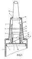
- FIG Cartridge gun 1 A cartridge system of a cartridge system according to the invention is shown in FIG Cartridge gun designated 1 and shown only in areas.
- Cartridge gun 1 is a pot-shaped in the front exit opening trained exit end 2 is used, which on the stimulus side Passage opening 3 has.
- the cartridge system also has a tubular, for example Plastic existing cartridge 4, which at its outlet end with a Fastening nozzle 5 is provided with an external thread 6.
- the cartridge 4 is in the Area of the fastening piece 5 on the inside with a membrane 7 locked.
- the membrane can alternatively also in the area of the outlet of the Fastening socket 5 may be arranged. This position of the membrane is in figure 1 indicated by dashed lines and designated by reference numeral 7 '.
- An outlet nozzle 8 is located on the attachment piece 5 of the cartridge 4 screwable, which in the embodiment of Figure 1 consists of two parts consists, namely a lower nozzle part 9 and an upper nozzle part 10.
- Das Upper nozzle part 10 is limited in the longitudinal direction within the Lower nozzle part 9 slidably arranged.
- the shift is thereby Limited locking means, namely first locking means and second locking means.
- the first Locking means are of a circumferential locking bead 11 on the outer circumference of the Upper nozzle part 10 and a corresponding locking groove 12 on the lower nozzle part 9 formed, while the second locking means of the locking bead 11 and one second, further inner locking groove 13 are formed in the lower nozzle part 9.
- the upper nozzle part 10 also has a circumferential stop 14 outside the area inserted into the lower nozzle part 9.
- a pointed, thorn-shaped end 15 is formed on the inner end of the nozzle upper part 10, which end is suitable for piercing the membrane 7 of the cartridge 4 with appropriate positioning.
- the geometric dimensions of the upper nozzle part 10 are chosen so that when the locking bead 11 is in the first locking groove 12 of the lower nozzle part 9, the piercing means 15 in the screwed-on position of the lower nozzle part 9, which is provided with an internal thread 16, do not enter the fastening socket 5 as far that they can come into contact with the membrane 7.
- the distance of the stop 14 is selected such that the stop 14 does not hinder this displacement movement, but rather in this position lies approximately at the free end of the lower nozzle part 9.
- the piercing means 15 are arranged such that in this position the piercing means 15 penetrate the membrane 7, ie open it.
- the cartridge system is handled in such a way that first the nozzle 8 is screwed onto the cartridge 4 or the attachment piece 5 of the cartridge 4 in the position of the lower nozzle part 9 and upper nozzle part 10 shown in the drawing.
- the cartridge 4 equipped in this way is then inserted into the cartridge gun in such a way that the stop 14 bears against the edge of the passage opening 3 of the cup-shaped outlet end 2 of the cartridge gun 1.
- the cartridge 4 is now pushed further into the cartridge gun 1 such that, due to the abutment of the stop 14, the upper nozzle part 10 is pushed into the lower nozzle part 9.
- the cartridge 4 is pressed forward when the gun 1 is actuated, so that the locking bead 11 engages in the second locking groove 13.
- the membrane 7 is pierced by the piercing means 15 and the cartridge 4 is opened so that the cartridge system is then ready for use.
- FIG. 2 is another embodiment of an inventive Cartridge system shown that largely corresponds to the embodiment according to FIG. 1. Therefore, they are the same Reference numerals as used in Figure 1, provided the same parts are affected.
- the embodiment according to 3 shows a shut-off valve 17 and handle 18 in the upper part 10 of the nozzle integrated. By closing this stopcock 17, it is possible Seal the cartridge system after application so that there is no more mass can emerge from the nozzle. This closed state is shown in Figure 2.
- the opening size of the stopcock 17 what is indicated by the double arrow in Figure 2, the volume flow in addition to Pressure build-up on the pistol grip can be varied. Above the stopcock 17 goes the upper nozzle part 10 into the nozzle tip.
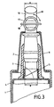
- FIG. 3 shows a further embodiment, that of the embodiment largely corresponds to Figure 2.
- the only difference of the embodiment 3 compared to that of Figure 2 is that the Upper nozzle part 10 opens into an external thread 19 above the shut-off valve 17, onto which a commercially available nozzle end piece, not shown, can be screwed.
- the upper nozzle part 10 has a length over its entire length essentially the same cross section on what is due to the Diameter specification a is indicated.
- the cartridge pistol can 1 can also be formed in one piece with the cup-shaped outlet end 2 and the like. more.
Landscapes
- Engineering & Computer Science (AREA)
- Mechanical Engineering (AREA)
- Physics & Mathematics (AREA)
- Geometry (AREA)
- Coating Apparatus (AREA)
- Packaging Of Annular Or Rod-Shaped Articles, Wearing Apparel, Cassettes, Or The Like (AREA)
Description
Besonders vorteilhaft ist vorgesehen, daß die Austrittsdüse aus einem am Befestigungsstutzen befestigbaren Düsenunterteil und einem in Längsrichtung begrenzt innerhalb des Düsenunterteiles verschiebbaren, am inneren Ende die Durchstechmittel aufweisenden Düsenoberteil besteht. Das Düsenunterteil kann dann zunächst bei noch geschlossener Kartusche auf den Befestigungsstutzen der Kartusche aufgesetzt bzw. aufgeschraubt werden und durch Längsverschiebung des Düsenoberteiles in das Düsenunterteil hinein wird dann automatisch die Membran der Kartusche durchstochen und somit die Öffnung der Kartusche freigegeben. Die Verschiebung des Düsenoberteiles kann vorteilhaft erst dann erfolgen, wenn die Kartusche schon in die Kartuschenpistole eingesetzt ist.
- Fig. 1
- in einem Teilschnitt eine erste Ausführungsform eines erfindungsgemäßen Kartuschensytemes,
- Fig. 2
- die Ausführungsform nach Fig. 1 mit einem in das Düsenoberteil integrierten Absperrhahn und
- Fig. 3
- die Ausführungsform nach Fig. 2 mit einer geringen Abwandlung.
Die Handhabung des Kartuschensystemes erfolgt derart, daß zunächst die Düse 8 in der in der Zeichnung dargestellten Position von Düsenunterteil 9 und Düsenoberteil 10 auf die Kartusche 4 bzw. die Befestigungsstutzen 5 der Kartusche 4 aufgeschraubt wird. Die so ausgerüstete Kartusche 4 wird anschließend in die Kartuschenpistole eingeführt, derart, daß der Anschlag 14 am Rand der Durchtrittsöffnung 3 des topfförmigen Austrittsendes 2 der Kartuschenpistole 1 anliegt. Die Kartusche 4 wird nun weiter in die Kartuschenpistole 1 eingeschoben, derart, daß aufgrund der Anlage des Anschlages 14 das Düsenoberteil 10 in das Düsenunterteil 9 hineingeschoben wird. Dabei wird die Kartusche 4 beim Betätigen der Pistole 1 nach vorne gedrückt, so daß die Rastwulst 11 in der zweiten Rastnut 13 einrastet. Bei diesem Vorgang wird die Membran 7 von den Durchstechmitteln 15 durchstochen und die Kartusche 4 ist geöffnet, so daß anschließend das Kartuschensystem einsatzbereit ist.
Claims (8)
- Kartuschensystem mit einer rohrförmigen Kartuschenpistole (1) und einer in die Kartuschenpistole (1) einsetzbaren Kartusche (4), welche mit ihrem Austrittsende in eingeführter Lage aus der Kartuschenpistole (1) herausragt, wobei die Kartusche (4) an ihrem Austrittsende mit einem Befestigungsstutzen (5) zum Befestigen einer Austrittsdüse (8) versehen ist, der Befestigungsstutzen (5) innenseitig mit einer durchstechbaren Membran (7, 7') verschlossen ist und die Austrittsdüse (8) am Befestigungsende mit in den Befestigungsstutzen (5) eingreifbaren Durchstechmitteln (15) zum Durchstechen der Membran (7) versehen ist,
dadurch gekennzeichnet, daß die Austrittsdüse (8) aus einem am Befestigungsstutzen (5) befestigbaren Düsenunterteil (9) und einem in Längsrichtung begrenzt innerhalb des Düsenunterteiles (9) verschiebbaren, am inneren Ende die Durchstechmittel (15) aufweisenden Düsenoberteil (10) besteht und daß das Düsenoberteil (10) und das Düsenunterteil (9) beabstandet voneinander jeweils erste und zweite korrespondierende Rastmittel (11, 12, 13) aufweisen, wobei das Düsenoberteil (10) entgegen der Wirkung der ersten Rastmittel (11, 12) in Längsrichtung bis in die Rastposition der zweiten Rastmittel (11, 13) verschiebbar ist. - Kartuschensystem nach Anspruch 1,
dadurch gekennzeichnet, daß das Düsenoberteil (10) außenseitig einen umlaufenden Anschlag (14) aufweist. - Kartuschensystem nach Anspruch 2,
dadurch gekennzeichnet, daß die Kartuschenpistole (1) ein topfförmig ausgebildetes Austrittsende (2) aufweist, welches das Düsenunterteil (9) und das Düsenoberteil (10) bereichsweise umgibt und eine Durchtrittsöffnung (3) für das Düsenoberteil (10) aufweist, deren Größe derart ist, daß das Düsenoberteil (10) in eingeführter Lage mit seinem Anschlag (14) in Anlage an den Rand der Austrittsöffnung (3) kommt. - Kartuschensystem nach Anspruch 3,
dadurch gekennzeichnet, daß das topfförmige Austrittsende (2) als Einzelteil ausgebildet ist, welches in die Kartuschenpistole (1) einsetzbar ist. - Kartuschensystem nach einem der Ansprüche 1 bis 4,
dadurch gekennzeichnet, daß die Membran (7) innerhalb der Kartusche (4) am Fuße des Befestigungsstutzens (5) angeordnet ist. - Kartuschensystem nach einem der Ansprüche 1 bis 4,
dadurch gekennzeichnet, daß die Membran (7') im Bereich des Austritts des Befestigungsstutzens (5) angeordnet ist. - Kartuschensystem nach einem der Ansprüche 1 bis 6,
dadurch gekennzeichnet, daß in das Düsenoberteil (10) ein Absperrhahn (17) integriert ist. - Kartuschensystem nach Anspruch 7,
dadurch gekennzeichnet, daß auf das freie Ende des Düsenoberteils (10) ein Düsenendstück aufschraubbar ist.
Applications Claiming Priority (3)
| Application Number | Priority Date | Filing Date | Title |
|---|---|---|---|
| DE19710878 | 1997-03-15 | ||
| DE19710878A DE19710878C1 (de) | 1997-03-15 | 1997-03-15 | Kartuschensystem |
| PCT/EP1998/001329 WO1998041334A1 (de) | 1997-03-15 | 1998-03-06 | Kartuschensystem |
Publications (2)
| Publication Number | Publication Date |
|---|---|
| EP0966329A1 EP0966329A1 (de) | 1999-12-29 |
| EP0966329B1 true EP0966329B1 (de) | 2002-08-28 |
Family
ID=7823550
Family Applications (1)
| Application Number | Title | Priority Date | Filing Date |
|---|---|---|---|
| EP98916897A Expired - Lifetime EP0966329B1 (de) | 1997-03-15 | 1998-03-06 | Kartuschensystem |
Country Status (8)
| Country | Link |
|---|---|
| US (1) | US6193108B1 (de) |
| EP (1) | EP0966329B1 (de) |
| AT (1) | ATE222811T1 (de) |
| AU (1) | AU7032398A (de) |
| CA (1) | CA2283952A1 (de) |
| DE (2) | DE19710878C1 (de) |
| PT (1) | PT966329E (de) |
| WO (1) | WO1998041334A1 (de) |
Families Citing this family (20)
| Publication number | Priority date | Publication date | Assignee | Title |
|---|---|---|---|---|
| ES2191420T3 (es) * | 1998-03-05 | 2003-09-01 | Henkel Kgaa | Envase con una tobera de descarga. |
| AUPP243598A0 (en) | 1998-03-18 | 1998-04-09 | Rapak Asia Pacific Limited | Improvements relating to tote bins |
| ES2254279T3 (es) * | 1998-10-14 | 2006-06-16 | KETTENBACH GMBH & CO. KG | Dispositivo para la apertura de una bolsa tubular que contenga una sustancia pastosa. |
| US6644509B1 (en) * | 1999-04-12 | 2003-11-11 | Kettenbach Gmbh & Co. Kg | Film packaging for a pasty-like substance |
| US6296149B1 (en) * | 1999-04-16 | 2001-10-02 | Depuy Orthopaedics, Inc. | Monomer delivery device for bone cement delivery system |
| US6435705B1 (en) | 1999-04-16 | 2002-08-20 | Depuy Orthopaedics, Inc. | Apparatus and method for delivering and mixing a liquid bone cement component with a powder bone cement component |
| EP1065153B1 (de) * | 1999-07-02 | 2004-03-17 | Kettenbach GmbH & CO. KG | Folienverpackung für eine pastöse Substanz |
| US6811341B2 (en) * | 2001-08-16 | 2004-11-02 | Closure Medical Corporation | Multiple-component combining |
| US6921192B2 (en) * | 2002-03-29 | 2005-07-26 | Depuy Orthopaedics, Inc. | Bone cement mixing apparatus |
| US7427005B1 (en) * | 2002-11-27 | 2008-09-23 | Owens-Illinois Closure Inc. | Dispensing closure, package and method of assembly with film seal piercing |
| ATE481584T1 (de) * | 2004-07-30 | 2010-10-15 | Gl Tool And Mfg Co Inc | Ventil |
| ATE555036T1 (de) * | 2005-10-07 | 2012-05-15 | Rainer Ammann | Verschluss |
| US8668400B2 (en) * | 2007-04-05 | 2014-03-11 | The Hartz Mountain Corporation | Fluid applicator |
| US8109236B2 (en) * | 2007-04-05 | 2012-02-07 | Sumitomo Corporation Of America | Fluid delivery assembly |
| EP2396237B1 (de) | 2009-02-13 | 2014-11-19 | Medmix Systems AG | Austragvorrichtung mit tube |
| DE102010062907A1 (de) * | 2010-12-13 | 2012-06-14 | Bayerische Motoren Werke Aktiengesellschaft | Auftragsvorrichtung zum Führen eines flüssigkeitsabgebenden Behältnisses von Hand |
| EP2897466A4 (de) * | 2012-09-21 | 2017-01-25 | Wilton Industries, Inc. | Kopplungselement für dressierbeutel |
| US9579686B2 (en) | 2012-10-29 | 2017-02-28 | Nordson Corporation | Fluid dispensing assemblies and methods of dispensing fluids from containers |
| WO2018090102A1 (en) * | 2016-11-18 | 2018-05-24 | Glenn Lee Marsh | A fluid container closure |
| US12378043B2 (en) * | 2021-10-06 | 2025-08-05 | Richard William Jenkins | Adhesive sealant discharge cap for handheld adhesive sealant tubes |
Family Cites Families (12)
| Publication number | Priority date | Publication date | Assignee | Title |
|---|---|---|---|---|
| US1880354A (en) * | 1931-07-30 | 1932-10-04 | Herman C Mueller | Fluid gun |
| US3193146A (en) * | 1962-10-08 | 1965-07-06 | R C Can Co | Dispensing gun |
| CH416446A (de) | 1963-11-06 | 1966-06-30 | Hoffmann Ag Geb | Dosendeckel mit Ausgiesser |
| EP0039245A1 (de) * | 1980-04-30 | 1981-11-04 | Black & Decker | Patrone |
| FR2500518A1 (fr) | 1981-02-20 | 1982-08-27 | Lincrusta | Cartouche destinee au conditionnement et a l'application de mastic ou de produits similaires |
| DE3217044C2 (de) * | 1982-05-06 | 1994-03-03 | Hilti Ag | Behälter für plastische Massen |
| US4461454A (en) * | 1982-06-01 | 1984-07-24 | New Product, Inc. | Caulking tube valve |
| CH669575A5 (de) * | 1985-08-20 | 1989-03-31 | Alfatechnic Ag | |
| EP0351358B1 (de) * | 1988-07-13 | 1992-03-18 | Gurit-Essex AG | Verfahren zum Ausstossen einer in einer Kartusche enthaltenen Substanz und Einrichtung zur Durchführung des Verfahrens |
| DE9017525U1 (de) * | 1990-12-28 | 1991-05-02 | Schneider, Friedhelm, 5226 Reichshof | Dosierpistole für Schlauchbeutel mit hochviskosem Inhalt |
| US5297697A (en) | 1993-07-23 | 1994-03-29 | Sonoco Products Company | Caulk cartridge with valve control |
| FR2729920B1 (fr) * | 1995-02-01 | 1997-06-06 | Kerplas Snc | Corps de flacon et flacon de distribution d'un produit |
-
1997
- 1997-03-15 DE DE19710878A patent/DE19710878C1/de not_active Expired - Fee Related
-
1998
- 1998-03-06 DE DE59805311T patent/DE59805311D1/de not_active Expired - Lifetime
- 1998-03-06 US US09/381,114 patent/US6193108B1/en not_active Expired - Fee Related
- 1998-03-06 EP EP98916897A patent/EP0966329B1/de not_active Expired - Lifetime
- 1998-03-06 AU AU70323/98A patent/AU7032398A/en not_active Abandoned
- 1998-03-06 PT PT98916897T patent/PT966329E/pt unknown
- 1998-03-06 CA CA002283952A patent/CA2283952A1/en not_active Abandoned
- 1998-03-06 WO PCT/EP1998/001329 patent/WO1998041334A1/de not_active Ceased
- 1998-03-06 AT AT98916897T patent/ATE222811T1/de not_active IP Right Cessation
Also Published As
| Publication number | Publication date |
|---|---|
| PT966329E (pt) | 2003-01-31 |
| US6193108B1 (en) | 2001-02-27 |
| EP0966329A1 (de) | 1999-12-29 |
| CA2283952A1 (en) | 1998-09-24 |
| ATE222811T1 (de) | 2002-09-15 |
| WO1998041334A1 (de) | 1998-09-24 |
| DE59805311D1 (de) | 2002-10-02 |
| DE19710878C1 (de) | 1998-07-02 |
| AU7032398A (en) | 1998-10-12 |
Similar Documents
| Publication | Publication Date | Title |
|---|---|---|
| DE19710878C1 (de) | Kartuschensystem | |
| EP0967701B1 (de) | Anschlussarmatur mit einem durch Schlitze in Halterungen aufgeteilten Befestigungsvorsprung | |
| DE2746517C3 (de) | Spritzeinrichtung | |
| DE2800701C2 (de) | ||
| EP1060106B1 (de) | Behälter mit einer auslassdüse | |
| EP0653359B1 (de) | Verschlussvorrichtung für einen Behälter mit einer handbetätigten Pumpe | |
| DE102008006491A1 (de) | Wirbelkörperersatzimplantat und Werkzeug zur Handhabung des Wirbelkörperersatzimplantates | |
| DE1934117B2 (de) | ||
| DE20104539U1 (de) | Intravenöse Kathetervorrichtung | |
| CH438588A (de) | Injektionsampulle | |
| DE102016207722A1 (de) | Flüssigkeitsspender | |
| DE102005031871B3 (de) | Anschluß-Vorrichtung für einen Wellschlauch | |
| DE2215605A1 (de) | Austeiler ventil für Aerosolbehälter | |
| DE102004044288A1 (de) | Vorrichtung zur Verbindung eines rohrförmigen Teils, insbesondere einer Kanüle, mit dem Inneren einer Flasche oder dergleichen | |
| EP0039374A1 (de) | Tube mit Schraubverschluss | |
| EP0943477B1 (de) | Kraftstoffbehälterverschluss | |
| DE202008001261U1 (de) | Wirbelkörperersatzimplantat und Werkzeug zur Handhabung des Wirbelkörperersatzimplantates | |
| EP0102083B1 (de) | Selbstschliessender Kraftstoffbehälterverschluss | |
| DE4114604C2 (de) | Sicherheitsvorrichtung für Getränkefaß | |
| DE2711186C3 (de) | Drehkolben-Auslaßventil, insbesondere für einen Dampfdruckkochkessel | |
| EP1262416B1 (de) | Behälter zur Aufnahme und Abgabe eines fliessfähigen Mediums | |
| DE3346614C2 (de) | ||
| DE4104009C2 (de) | Kupplungsstück . | |
| DE3112516A1 (de) | "schraubverschluss fuer kraftstofftanks o.dgl." | |
| DE9001274U1 (de) | Vorrichtung zur Kupplung eines unter Druck stehenden Vorratsbehälters mit einer Ausgabeeinrichtung |
Legal Events
| Date | Code | Title | Description |
|---|---|---|---|
| PUAI | Public reference made under article 153(3) epc to a published international application that has entered the european phase |
Free format text: ORIGINAL CODE: 0009012 |
|
| 17P | Request for examination filed |
Effective date: 19990907 |
|
| AK | Designated contracting states |
Kind code of ref document: A1 Designated state(s): AT BE CH DE DK ES FI FR GB GR IE IT LI LU MC NL PT SE |
|
| 17Q | First examination report despatched |
Effective date: 20010803 |
|
| GRAG | Despatch of communication of intention to grant |
Free format text: ORIGINAL CODE: EPIDOS AGRA |
|
| GRAG | Despatch of communication of intention to grant |
Free format text: ORIGINAL CODE: EPIDOS AGRA |
|
| GRAH | Despatch of communication of intention to grant a patent |
Free format text: ORIGINAL CODE: EPIDOS IGRA |
|
| GRAH | Despatch of communication of intention to grant a patent |
Free format text: ORIGINAL CODE: EPIDOS IGRA |
|
| GRAA | (expected) grant |
Free format text: ORIGINAL CODE: 0009210 |
|
| AK | Designated contracting states |
Kind code of ref document: B1 Designated state(s): AT BE CH DE DK ES FI FR GB GR IE IT LI LU MC NL PT SE |
|
| PG25 | Lapsed in a contracting state [announced via postgrant information from national office to epo] |
Ref country code: GR Free format text: LAPSE BECAUSE OF FAILURE TO SUBMIT A TRANSLATION OF THE DESCRIPTION OR TO PAY THE FEE WITHIN THE PRESCRIBED TIME-LIMIT Effective date: 20020828 Ref country code: FI Free format text: LAPSE BECAUSE OF FAILURE TO SUBMIT A TRANSLATION OF THE DESCRIPTION OR TO PAY THE FEE WITHIN THE PRESCRIBED TIME-LIMIT Effective date: 20020828 |
|
| REF | Corresponds to: |
Ref document number: 222811 Country of ref document: AT Date of ref document: 20020915 Kind code of ref document: T |
|
| REG | Reference to a national code |
Ref country code: GB Ref legal event code: FG4D Free format text: NOT ENGLISH |
|
| REG | Reference to a national code |
Ref country code: CH Ref legal event code: EP |
|
| REF | Corresponds to: |
Ref document number: 59805311 Country of ref document: DE Date of ref document: 20021002 |
|
| REG | Reference to a national code |
Ref country code: IE Ref legal event code: FG4D Free format text: GERMAN |
|
| GBT | Gb: translation of ep patent filed (gb section 77(6)(a)/1977) |
Effective date: 20021011 |
|
| PG25 | Lapsed in a contracting state [announced via postgrant information from national office to epo] |
Ref country code: SE Free format text: LAPSE BECAUSE OF FAILURE TO SUBMIT A TRANSLATION OF THE DESCRIPTION OR TO PAY THE FEE WITHIN THE PRESCRIBED TIME-LIMIT Effective date: 20021128 Ref country code: DK Free format text: LAPSE BECAUSE OF FAILURE TO SUBMIT A TRANSLATION OF THE DESCRIPTION OR TO PAY THE FEE WITHIN THE PRESCRIBED TIME-LIMIT Effective date: 20021128 |
|
| ET | Fr: translation filed | ||
| REG | Reference to a national code |
Ref country code: PT Ref legal event code: SC4A Free format text: AVAILABILITY OF NATIONAL TRANSLATION Effective date: 20021121 |
|
| PG25 | Lapsed in a contracting state [announced via postgrant information from national office to epo] |
Ref country code: ES Free format text: LAPSE BECAUSE OF FAILURE TO SUBMIT A TRANSLATION OF THE DESCRIPTION OR TO PAY THE FEE WITHIN THE PRESCRIBED TIME-LIMIT Effective date: 20030228 |
|
| PLBE | No opposition filed within time limit |
Free format text: ORIGINAL CODE: 0009261 |
|
| STAA | Information on the status of an ep patent application or granted ep patent |
Free format text: STATUS: NO OPPOSITION FILED WITHIN TIME LIMIT |
|
| 26N | No opposition filed |
Effective date: 20030530 |
|
| PGFP | Annual fee paid to national office [announced via postgrant information from national office to epo] |
Ref country code: CH Payment date: 20060301 Year of fee payment: 9 |
|
| PGFP | Annual fee paid to national office [announced via postgrant information from national office to epo] |
Ref country code: PT Payment date: 20060306 Year of fee payment: 9 |
|
| PGFP | Annual fee paid to national office [announced via postgrant information from national office to epo] |
Ref country code: LU Payment date: 20060310 Year of fee payment: 9 |
|
| PGFP | Annual fee paid to national office [announced via postgrant information from national office to epo] |
Ref country code: AT Payment date: 20060313 Year of fee payment: 9 Ref country code: IE Payment date: 20060313 Year of fee payment: 9 |
|
| PGFP | Annual fee paid to national office [announced via postgrant information from national office to epo] |
Ref country code: MC Payment date: 20061212 Year of fee payment: 10 |
|
| PG25 | Lapsed in a contracting state [announced via postgrant information from national office to epo] |
Ref country code: PT Free format text: LAPSE BECAUSE OF NON-PAYMENT OF DUE FEES Effective date: 20070906 |
|
| REG | Reference to a national code |
Ref country code: PT Ref legal event code: MM4A Free format text: LAPSE DUE TO NON-PAYMENT OF FEES Effective date: 20070906 |
|
| REG | Reference to a national code |
Ref country code: CH Ref legal event code: PL |
|
| PG25 | Lapsed in a contracting state [announced via postgrant information from national office to epo] |
Ref country code: AT Free format text: LAPSE BECAUSE OF NON-PAYMENT OF DUE FEES Effective date: 20070306 |
|
| REG | Reference to a national code |
Ref country code: IE Ref legal event code: MM4A |
|
| PGFP | Annual fee paid to national office [announced via postgrant information from national office to epo] |
Ref country code: IT Payment date: 20070519 Year of fee payment: 10 |
|
| PG25 | Lapsed in a contracting state [announced via postgrant information from national office to epo] |
Ref country code: IE Free format text: LAPSE BECAUSE OF NON-PAYMENT OF DUE FEES Effective date: 20070306 |
|
| PG25 | Lapsed in a contracting state [announced via postgrant information from national office to epo] |
Ref country code: CH Free format text: LAPSE BECAUSE OF NON-PAYMENT OF DUE FEES Effective date: 20070331 Ref country code: LI Free format text: LAPSE BECAUSE OF NON-PAYMENT OF DUE FEES Effective date: 20070331 |
|
| PG25 | Lapsed in a contracting state [announced via postgrant information from national office to epo] |
Ref country code: MC Free format text: LAPSE BECAUSE OF NON-PAYMENT OF DUE FEES Effective date: 20080331 |
|
| PG25 | Lapsed in a contracting state [announced via postgrant information from national office to epo] |
Ref country code: LU Free format text: LAPSE BECAUSE OF NON-PAYMENT OF DUE FEES Effective date: 20070306 Ref country code: IT Free format text: LAPSE BECAUSE OF NON-PAYMENT OF DUE FEES Effective date: 20080306 |
|
| PGFP | Annual fee paid to national office [announced via postgrant information from national office to epo] |
Ref country code: NL Payment date: 20140308 Year of fee payment: 17 |
|
| PGFP | Annual fee paid to national office [announced via postgrant information from national office to epo] |
Ref country code: FR Payment date: 20140311 Year of fee payment: 17 |
|
| PGFP | Annual fee paid to national office [announced via postgrant information from national office to epo] |
Ref country code: GB Payment date: 20140305 Year of fee payment: 17 |
|
| PGFP | Annual fee paid to national office [announced via postgrant information from national office to epo] |
Ref country code: BE Payment date: 20140312 Year of fee payment: 17 |
|
| PGFP | Annual fee paid to national office [announced via postgrant information from national office to epo] |
Ref country code: DE Payment date: 20140417 Year of fee payment: 17 |
|
| REG | Reference to a national code |
Ref country code: DE Ref legal event code: R119 Ref document number: 59805311 Country of ref document: DE |
|
| GBPC | Gb: european patent ceased through non-payment of renewal fee |
Effective date: 20150306 |
|
| REG | Reference to a national code |
Ref country code: NL Ref legal event code: MM Effective date: 20150401 |
|
| REG | Reference to a national code |
Ref country code: FR Ref legal event code: ST Effective date: 20151130 |
|
| PG25 | Lapsed in a contracting state [announced via postgrant information from national office to epo] |
Ref country code: DE Free format text: LAPSE BECAUSE OF NON-PAYMENT OF DUE FEES Effective date: 20151001 Ref country code: GB Free format text: LAPSE BECAUSE OF NON-PAYMENT OF DUE FEES Effective date: 20150306 |
|
| PG25 | Lapsed in a contracting state [announced via postgrant information from national office to epo] |
Ref country code: FR Free format text: LAPSE BECAUSE OF NON-PAYMENT OF DUE FEES Effective date: 20150331 |
|
| PG25 | Lapsed in a contracting state [announced via postgrant information from national office to epo] |
Ref country code: NL Free format text: LAPSE BECAUSE OF NON-PAYMENT OF DUE FEES Effective date: 20150401 |
|
| PG25 | Lapsed in a contracting state [announced via postgrant information from national office to epo] |
Ref country code: BE Free format text: LAPSE BECAUSE OF NON-PAYMENT OF DUE FEES Effective date: 20150331 |