EP0965703B1 - Rahmenwerk für Gebäudefassaden, Dächer und dgl. - Google Patents
Rahmenwerk für Gebäudefassaden, Dächer und dgl. Download PDFInfo
- Publication number
- EP0965703B1 EP0965703B1 EP99109573A EP99109573A EP0965703B1 EP 0965703 B1 EP0965703 B1 EP 0965703B1 EP 99109573 A EP99109573 A EP 99109573A EP 99109573 A EP99109573 A EP 99109573A EP 0965703 B1 EP0965703 B1 EP 0965703B1
- Authority
- EP
- European Patent Office
- Prior art keywords
- uprights
- framework
- elements
- bars
- tensioning elements
- Prior art date
- Legal status (The legal status is an assumption and is not a legal conclusion. Google has not performed a legal analysis and makes no representation as to the accuracy of the status listed.)
- Expired - Lifetime
Links
- 238000010276 construction Methods 0.000 title description 6
- 238000000926 separation method Methods 0.000 claims 1
- 238000009434 installation Methods 0.000 abstract description 2
- 239000011521 glass Substances 0.000 description 4
- 229910052782 aluminium Inorganic materials 0.000 description 2
- XAGFODPZIPBFFR-UHFFFAOYSA-N aluminium Chemical compound [Al] XAGFODPZIPBFFR-UHFFFAOYSA-N 0.000 description 2
- 238000000034 method Methods 0.000 description 2
- 238000001125 extrusion Methods 0.000 description 1
- 238000004519 manufacturing process Methods 0.000 description 1
- 239000000463 material Substances 0.000 description 1
- 229910052751 metal Inorganic materials 0.000 description 1
- 239000002184 metal Substances 0.000 description 1
- 238000003825 pressing Methods 0.000 description 1
Images


Classifications
-
- E—FIXED CONSTRUCTIONS
- E04—BUILDING
- E04B—GENERAL BUILDING CONSTRUCTIONS; WALLS, e.g. PARTITIONS; ROOFS; FLOORS; CEILINGS; INSULATION OR OTHER PROTECTION OF BUILDINGS
- E04B2/00—Walls, e.g. partitions, for buildings; Wall construction with regard to insulation; Connections specially adapted to walls
- E04B2/88—Curtain walls
- E04B2/96—Curtain walls comprising panels attached to the structure through mullions or transoms
-
- E—FIXED CONSTRUCTIONS
- E04—BUILDING
- E04D—ROOF COVERINGS; SKY-LIGHTS; GUTTERS; ROOF-WORKING TOOLS
- E04D3/00—Roof covering by making use of flat or curved slabs or stiff sheets
- E04D3/02—Roof covering by making use of flat or curved slabs or stiff sheets of plane slabs, slates, or sheets, or in which the cross-section is unimportant
- E04D3/06—Roof covering by making use of flat or curved slabs or stiff sheets of plane slabs, slates, or sheets, or in which the cross-section is unimportant of glass or other translucent material; Fixing means therefor
- E04D3/08—Roof covering by making use of flat or curved slabs or stiff sheets of plane slabs, slates, or sheets, or in which the cross-section is unimportant of glass or other translucent material; Fixing means therefor with metal glazing bars
-
- E—FIXED CONSTRUCTIONS
- E04—BUILDING
- E04B—GENERAL BUILDING CONSTRUCTIONS; WALLS, e.g. PARTITIONS; ROOFS; FLOORS; CEILINGS; INSULATION OR OTHER PROTECTION OF BUILDINGS
- E04B1/00—Constructions in general; Structures which are not restricted either to walls, e.g. partitions, or floors or ceilings or roofs
- E04B1/35—Extraordinary methods of construction, e.g. lift-slab, jack-block
- E04B2001/3583—Extraordinary methods of construction, e.g. lift-slab, jack-block using permanent tensioning means, e.g. cables or rods, to assemble or rigidify structures (not pre- or poststressing concrete), e.g. by tying them around the structure
Definitions
- the invention relates to a framework for building facades, roofs or the like. according to the preamble of claim 1.
- the posts and transoms in such frameworks are preferably made of plastic or made of aluminum hollow profiles.
- the infills are depending on the design of the Building filled with glass panes or opaque panels.
- the bars are fixed to the posts using transom connectors.
- German layout specification 1 109 345 discloses a generic framework for building facades, where each post and transom consists of so-called half-posts and half transoms consists.
- Each half post consists of two identical shell profiles, which in the final assembly position is positively connected to one another by terminal strips so that a closed, composed of several parts Hollow profile post is created.
- the bars are constructed in a similar way, with projections and interlocking interlocking and held together by cap screws become.
- the half-bars and half-posts are interconnected by tie rods connected.
- the tie rods engage in guides of the half-bar profiles in order to access them wear.
- Each tie rod ends immediately within a frame construction after engaging in a half post profile and is with this over pressure plates and nuts screwed.
- the skeleton is constructed so that it is for the Transport disassembled into as many individual parts as possible and the individual parts later at the installation site can be put together.
- the invention has for its object to provide a framework for building facades consisting of several frame elements, Roofs or the like already in a workshop or a manufacturing company to be assembled in such a way that it is largely pre-assembled to the construction site can be transported without losing its stability during transport to lose.
- the proposal according to the invention makes it possible to assemble the framework to be carried out completely in the supplier's company, after assembling the the mullions and transoms formed in a final work step Clamping profiles are used and connected to the outer mounting posts.
- Clamping profiles are used and connected to the outer mounting posts.
- Each is preferably Framework composed of several pre-assembled frame elements. ever according to the number and size of the frame elements of each framework the clamping profiles are designed accordingly.
- the clamping profiles expediently run within the bars designed as hollow profiles and through openings of the posts in the correct position therethrough.
- the clamping profiles are invisible from the outside and it is Particularly suitable if the infills are filled with transparent glass panes become.
- the guides can be easily in the pressing process include.
- connections between the mullions and the transoms are made using transom connectors, then you can on special guides in the profile cross sections of the Latches may be dispensed with.
- the mullions and transoms can consist of aluminum hollow profiles, but also of Plastic hollow profiles.
- the thermal expansion that is unavoidable in construction to compensate is provided in a special embodiment of the subject of the invention, that between the fasteners placed on the end of the clamping profiles and strain compensation elements are provided on at least one side.
- the clamping profiles are made of Round bars, preferably made of tubes with external or internal threads at the ends exist, the fasteners corresponding nuts or bolts and the Expansion compensation elements are disc springs. With a thermal As is well known, the disk springs are stretched more extensively. Go this Expansion back, the disc springs relax without being in the Unwanted joints arise in connection areas.
- the outer Assembly posts are designed as closed or semi-open profile sections, preferably the cross sections of the cross sections of the middle posts correspond or approximate.
- the cross section corresponds to the left or to the right of the axis of symmetry cross section of a closed post section.
- the half-open profile sections offer the advantage that the Connecting elements and the expansion compensation elements are easy to assemble.
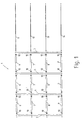
- the framework shown as a whole in FIG. 1 is 1 the example shown from nine individual frame fields, each from above and are delimited at the bottom by transoms and laterally by post part lengths Three each Frame fields with the side and top post and transom boundaries correspond to a frame element.
- the entire framework shown comprises three Frame elements that can be preassembled.
- the framework 1 has two outer mounting posts 2.3 on and two parallel middle posts 4.5. There are four bars between the mounting posts 2, 3 and the middle posts 4, 5 6,7,8,9 arranged.
- the number of posts 4.5 and the number of bars 6-9 depends according to the width and height of the framework 1 or number of each Facade elements and with each other according to the specified distances. Bars 6-9 are connected to each other by bolt connectors 10 in a known manner.
- the framework 1 after the Proposed invention by four clamping profiles running in the direction of the bars 6-9 11, 12, 13, 14 connected to one another in a torsionally stiff manner in a manner explained in more detail.
- Clamping profiles 11-14 are suitable rods or tubes. The ends of the Clamping profiles are fixed to the outer assembly posts 2,3.
- the clamping profiles 11-14 through the interior of the Bolts 6-9 and through appropriate openings in the middle posts 4,5 passed.
- the on in the drawing is not shown parts of the building definable, also provided with openings outer Assembly post 2,3 formed as a half-open profile sections, the open sides to the outside, i.e. lie on the opposite sides.
- the clamping profiles 11-14 are tubes in the embodiment shown, which are provided at the ends with an internal thread are so that they are fixed by means of screws 15, 16 to the mounting posts 2, 3 can.
- the lengths of the clamping profiles 11-14 be slightly shorter than the clear distance between the facing surfaces of the Assembly post 2,3.
- expansion compensation elements in the form of disc springs 17,18 arranged.
- the posts 2-5 are connected to the transoms 6-9 by the transom connectors 10, in the bolt connectors and in the bolts 6-9 guides for the clamping profiles 11-14 are provided.
- the bolt connector 10 can be omitted if the guides in the Bars are stable enough.
- Those bounded by bars 6-9 and posts 2-5 Frame fields are in a known manner with insulating glass panes 19 or panels filled out, which can also be assembled at the factory.
- Figure 3 illustrates how e.g. three individual frameworks 1 to form an overall framework of a building under construction is completed, which the building facade or forms part of a facade.
- the assembly direction can be from left to right right, from bottom to top or vice versa.
Landscapes
- Engineering & Computer Science (AREA)
- Architecture (AREA)
- Civil Engineering (AREA)
- Structural Engineering (AREA)
- Physics & Mathematics (AREA)
- Electromagnetism (AREA)
- Load-Bearing And Curtain Walls (AREA)
- Building Environments (AREA)
- Greenhouses (AREA)
- Joining Of Building Structures In Genera (AREA)
- Door And Window Frames Mounted To Openings (AREA)
Description
- Figur 1:
- ein erfindungsgemäßes Rahmenwerk für Fassaden, Dächer oder dgl. mit mehreren Rahmenelementen in einer Frontansicht in auseinandergezogener, schematischer Darstellung,
- Figur 2:
- die montierten Pfosten und Riegel des Rahmenwerks nach Figur 1 in einer Schnittdarstellung quer zu den Pfosten und
- Figur 3:
- mehrere aneinander gereihte, aus einzelnen Rahmenelementen bestehende Rahmenwerke nach Figur 1.
- 1
- Rahmenwerk
- 2
- Montagepfosten
- 3
- Montagepfosten
- 4
- mittlerer Pfosten
- 5
- mittlerer Pfosten
- 6,7,8,9
- Riegel
- 10
- Riegelverbinder
- 11,12,13,14
- Spannprofile
- 15,16
- Schrauben
- 17,18
- Tellerfedern
- 19
- Isolierglasscheibe
Claims (6)
- Rahmenwerk für Gebäudefassaden, Dächer oder dergleichen mit zumindest einem aus Pfosten (2 - 5) und winkelig dazu stehenden Riegeln (6 - 9) begrenzten Rahmenelement, wobei die Pfosten (2-5) äußere Montagepfosten (2, 3) und mittlere Pfosten (4, 5) umfassen, wobei das Rahmenelement mit einer oder mehreren Ausfachungen (19) zur Aufnahme von Scheiben, Paneelen oder dergleichen versehen ist, wobei zumindest die Pfosten (2 - 5) jedes Rahmenelementes durch ein oder mehrere winkelig zu den Pfosten und im Abstand zueinander verlaufende Spannprofile (11-14) verwindungssteif miteinander verbunden sind und die Spannprofile (11 - 14) innerhalb der als Hohlprofile ausgebildeten und mit Führungen versehenen Riegel verlaufen, die Pfosten (2 - 5) und Riegel (6 - 9) durch in ihrem Querschnitt mit Führungen für die Spannprofile (11 - 14) versehene Riegelverbinder (10) verbunden sind und die Pfosten (2 - 5) lagegerechte Öffnungen zum Durchdringen der Pfosten mittels der Spannprofile (11 - 14) aufweisen, dadurch gekennzeichnet, dass die Spannprofile (11 - 14) ununterbrochen durch mehrere Riegel (6 - 9) verlaufen und die Enden der Spannprofile an den äußeren Montagepfosten (2, 3) festgelegt sind.
- Rahmenwerk nach Anspruch 1, dadurch gekennzeichnet, dass jedes Rahmenwerk aus mehreren vormontierbaren Rahmenelementen zusammengesetzt ist.
- Rahmenwerk nach einem oder mehreren der Ansprüche 1 oder 2, dadurch gekennzeichnet, dass zwischen den endseitig auf die Spannprofile (11-14) aufgesetzten Befestigungselementen (15, 16) und den bauseitigen Montagepfosten (2, 3) jedes Rahmenelements an wenigstens einer Seite Dehnungsausgleichselemente (17, 18) vorgesehen sind.
- Rahmenwerk nach Anspruch 3, dadurch gekennzeichnet, dass die Spannprofile aus Rundstangen (11-14), vorzugsweise aus Rohren mit endseitigen Außen- und Innengewinden bestehen und dass die Befestigungselemente, Muttern oder Schrauben (15, 16) und die Dehnungsausgleichselemente Tellerfedern (17, 18) sind.
- Rahmenwerk nach einem oder mehreren der vorherigen Ansprüche 1 bis 4, dadurch gekennzeichnet, dass die äußere Montagepfosten (2, 3) als geschlossene oder als halboffene Profilabschnitte ausgebildet sind.
- Rahmenwerk nach Anspruch 5, dadurch gekennzeichnet, dass die Querschnitte der äußeren Montagepfosten (2, 3) den Querschnitten der mittleren Pfosten (4, 5) entsprechen oder annähernd entsprechen.
Applications Claiming Priority (2)
| Application Number | Priority Date | Filing Date | Title |
|---|---|---|---|
| DE19827397 | 1998-06-19 | ||
| DE19827397A DE19827397C1 (de) | 1998-06-19 | 1998-06-19 | Rahmenwerk für Gebäudefassaden, Dächer oder dgl. |
Publications (3)
| Publication Number | Publication Date |
|---|---|
| EP0965703A2 EP0965703A2 (de) | 1999-12-22 |
| EP0965703A3 EP0965703A3 (de) | 2000-11-15 |
| EP0965703B1 true EP0965703B1 (de) | 2004-11-17 |
Family
ID=7871433
Family Applications (1)
| Application Number | Title | Priority Date | Filing Date |
|---|---|---|---|
| EP99109573A Expired - Lifetime EP0965703B1 (de) | 1998-06-19 | 1999-05-14 | Rahmenwerk für Gebäudefassaden, Dächer und dgl. |
Country Status (5)
| Country | Link |
|---|---|
| EP (1) | EP0965703B1 (de) |
| AT (1) | ATE282744T1 (de) |
| DE (2) | DE19827397C1 (de) |
| NO (1) | NO992402L (de) |
| SK (1) | SK83699A3 (de) |
Families Citing this family (3)
| Publication number | Priority date | Publication date | Assignee | Title |
|---|---|---|---|---|
| AU8012000A (en) | 1999-10-08 | 2001-04-23 | Diversified Panel Systems, Inc. | Curtain wall support method and apparatus |
| US6745527B1 (en) | 1999-10-08 | 2004-06-08 | Diversified Panel Systems, Inc. | Curtain wall support method and apparatus |
| CN113738121A (zh) * | 2021-08-16 | 2021-12-03 | 苏州市鑫泰建筑装璜有限公司 | 一种高层建筑玻璃幕墙结构的优化方法 |
Family Cites Families (6)
| Publication number | Priority date | Publication date | Assignee | Title |
|---|---|---|---|---|
| CH330392A (fr) * | 1956-02-22 | 1958-06-15 | Engel Charles | Ossature métallique de cloison pour immeuble |
| GB2078273A (en) * | 1980-06-26 | 1982-01-06 | Cold Rolled Sections Ltd | Building Frameworks |
| US4860517A (en) * | 1987-07-24 | 1989-08-29 | Hulett Aluminium Limited | Framework structure for windows and doors |
| DE4123604A1 (de) * | 1991-07-17 | 1993-01-21 | Franz Hoefler | Fassadenelement mit wenigstens einer glasscheibe |
| DE4223694C2 (de) * | 1992-07-21 | 1994-05-26 | Danz Robert | Konstruktions-Bauelement für die Verglasung von Bauten |
| DE19525957C2 (de) * | 1995-07-17 | 2000-02-03 | Wicona Bausysteme Gmbh | Warmfassade |
-
1998
- 1998-06-19 DE DE19827397A patent/DE19827397C1/de not_active Expired - Fee Related
-
1999
- 1999-05-14 EP EP99109573A patent/EP0965703B1/de not_active Expired - Lifetime
- 1999-05-14 DE DE59911071T patent/DE59911071D1/de not_active Expired - Fee Related
- 1999-05-14 AT AT99109573T patent/ATE282744T1/de not_active IP Right Cessation
- 1999-05-20 NO NO992402A patent/NO992402L/no not_active Application Discontinuation
- 1999-06-18 SK SK836-99A patent/SK83699A3/sk unknown
Also Published As
| Publication number | Publication date |
|---|---|
| NO992402L (no) | 1999-12-20 |
| DE59911071D1 (de) | 2004-12-23 |
| DE19827397C1 (de) | 2000-03-09 |
| EP0965703A3 (de) | 2000-11-15 |
| ATE282744T1 (de) | 2004-12-15 |
| EP0965703A2 (de) | 1999-12-22 |
| NO992402D0 (no) | 1999-05-20 |
| SK83699A3 (en) | 2000-02-14 |
Similar Documents
| Publication | Publication Date | Title |
|---|---|---|
| DE3430612A1 (de) | Metall-raumfachwerk aus einzelelementen zum errichten von gebaeuden | |
| DE2054385A1 (de) | Rahmenfachwerk | |
| EP0965703B1 (de) | Rahmenwerk für Gebäudefassaden, Dächer und dgl. | |
| DE4040006A1 (de) | Glaswand | |
| DE19638538A1 (de) | Bauelement zur Wärmedämmung | |
| DE69002931T2 (de) | Modultrennwand zum Bau von Lokalen. | |
| DE102014119021B4 (de) | Anordnung zum Befestigen eines Pfostens aus Kunststoff an einer Rahmenleiste eines Fensters oder einer Türe mittels eines Pfostenverbinders | |
| EP0523694A1 (de) | Verbundprofil für Rahmen von Wandelementen, Türen und Fenstern | |
| DE3444305A1 (de) | Baueinheit zur bildung einer wand, decke oder tuer einer sauna- oder dampfbadkabine | |
| DE2724377A1 (de) | Profilstabaggregat | |
| DE3941288C2 (de) | ||
| DE102013106598A1 (de) | Schalungselement mit Schalungsplatten und Bewehrungskorb | |
| DE3617445C2 (de) | ||
| DE69924768T2 (de) | Rahmenstruktur, sowie ein Fensterrahmen, eine Fassadenstruktur oder dergleichen | |
| DE4340965C1 (de) | Spinn- oder Zwirnmaschine | |
| DE1658915C3 (de) | Trennwand | |
| CH685132A5 (de) | Abstandhalter für einzubetonierende Bewehrungseisen. | |
| DE2422771C3 (de) | Raumfachwerk | |
| DE3246708C1 (de) | Sporttor | |
| EP1260644A2 (de) | Dachelement, Bauwerk und Verfahren zum Herstellen eines derartigen Bauwerkes | |
| DE19933252B4 (de) | Trennwandsystem | |
| DE29721095U1 (de) | Netzwerk aus Stabknoten | |
| AT334055B (de) | Befestigungselement zur montage liegender gasbetonfertigteilwandelemente an saulen, insbesondere betonsaulen | |
| CH584317A5 (en) | Open structure for wall or ceiling - consists of parallel beams connected with diagonal members with bolting flanges | |
| DE2028777C (de) | Der Luft oder Gasreinigung dienende Hangedecke, insbesondere fur weiße oder reine Räume |
Legal Events
| Date | Code | Title | Description |
|---|---|---|---|
| PUAI | Public reference made under article 153(3) epc to a published international application that has entered the european phase |
Free format text: ORIGINAL CODE: 0009012 |
|
| AK | Designated contracting states |
Kind code of ref document: A2 Designated state(s): AT BE CH DE DK FR GB IT LI NL SE |
|
| AX | Request for extension of the european patent |
Free format text: AL;LT;LV;MK;RO;SI |
|
| PUAL | Search report despatched |
Free format text: ORIGINAL CODE: 0009013 |
|
| AK | Designated contracting states |
Kind code of ref document: A3 Designated state(s): AT BE CH CY DE DK ES FI FR GB GR IE IT LI LU MC NL PT SE |
|
| AX | Request for extension of the european patent |
Free format text: AL;LT;LV;MK;RO;SI |
|
| 17P | Request for examination filed |
Effective date: 20001123 |
|
| AKX | Designation fees paid |
Free format text: AT BE CH DE DK FR GB IT LI NL SE |
|
| 17Q | First examination report despatched |
Effective date: 20030307 |
|
| GRAP | Despatch of communication of intention to grant a patent |
Free format text: ORIGINAL CODE: EPIDOSNIGR1 |
|
| GRAS | Grant fee paid |
Free format text: ORIGINAL CODE: EPIDOSNIGR3 |
|
| GRAA | (expected) grant |
Free format text: ORIGINAL CODE: 0009210 |
|
| AK | Designated contracting states |
Kind code of ref document: B1 Designated state(s): AT BE CH DE DK FR GB IT LI NL SE |
|
| REG | Reference to a national code |
Ref country code: GB Ref legal event code: FG4D Free format text: NOT ENGLISH |
|
| REG | Reference to a national code |
Ref country code: CH Ref legal event code: EP |
|
| REF | Corresponds to: |
Ref document number: 59911071 Country of ref document: DE Date of ref document: 20041223 Kind code of ref document: P |
|
| REG | Reference to a national code |
Ref country code: CH Ref legal event code: NV Representative=s name: PA ALDO ROEMPLER |
|
| PG25 | Lapsed in a contracting state [announced via postgrant information from national office to epo] |
Ref country code: SE Free format text: LAPSE BECAUSE OF FAILURE TO SUBMIT A TRANSLATION OF THE DESCRIPTION OR TO PAY THE FEE WITHIN THE PRESCRIBED TIME-LIMIT Effective date: 20050217 Ref country code: DK Free format text: LAPSE BECAUSE OF FAILURE TO SUBMIT A TRANSLATION OF THE DESCRIPTION OR TO PAY THE FEE WITHIN THE PRESCRIBED TIME-LIMIT Effective date: 20050217 |
|
| GBT | Gb: translation of ep patent filed (gb section 77(6)(a)/1977) |
Effective date: 20050317 |
|
| PLBE | No opposition filed within time limit |
Free format text: ORIGINAL CODE: 0009261 |
|
| STAA | Information on the status of an ep patent application or granted ep patent |
Free format text: STATUS: NO OPPOSITION FILED WITHIN TIME LIMIT |
|
| ET | Fr: translation filed | ||
| 26N | No opposition filed |
Effective date: 20050818 |
|
| PGFP | Annual fee paid to national office [announced via postgrant information from national office to epo] |
Ref country code: IT Payment date: 20060531 Year of fee payment: 8 |
|
| REG | Reference to a national code |
Ref country code: CH Ref legal event code: PCAR Free format text: ALDO ROEMPLER PATENTANWALT;BRENDENWEG 11 POSTFACH 154;9424 RHEINECK (CH) |
|
| PGFP | Annual fee paid to national office [announced via postgrant information from national office to epo] |
Ref country code: BE Payment date: 20080417 Year of fee payment: 10 |
|
| PGFP | Annual fee paid to national office [announced via postgrant information from national office to epo] |
Ref country code: NL Payment date: 20080526 Year of fee payment: 10 Ref country code: CH Payment date: 20080821 Year of fee payment: 10 |
|
| PGFP | Annual fee paid to national office [announced via postgrant information from national office to epo] |
Ref country code: GB Payment date: 20080520 Year of fee payment: 10 |
|
| PGFP | Annual fee paid to national office [announced via postgrant information from national office to epo] |
Ref country code: DE Payment date: 20090512 Year of fee payment: 11 Ref country code: AT Payment date: 20090529 Year of fee payment: 11 |
|
| PG25 | Lapsed in a contracting state [announced via postgrant information from national office to epo] |
Ref country code: IT Free format text: LAPSE BECAUSE OF NON-PAYMENT OF DUE FEES Effective date: 20070514 |
|
| BERE | Be: lapsed |
Owner name: EDUARD *HUECK G.M.B.H. & CO. K.G. Effective date: 20090531 |
|
| REG | Reference to a national code |
Ref country code: CH Ref legal event code: PL |
|
| GBPC | Gb: european patent ceased through non-payment of renewal fee |
Effective date: 20090514 |
|
| PG25 | Lapsed in a contracting state [announced via postgrant information from national office to epo] |
Ref country code: LI Free format text: LAPSE BECAUSE OF NON-PAYMENT OF DUE FEES Effective date: 20090531 Ref country code: CH Free format text: LAPSE BECAUSE OF NON-PAYMENT OF DUE FEES Effective date: 20090531 |
|
| NLV4 | Nl: lapsed or anulled due to non-payment of the annual fee |
Effective date: 20091201 |
|
| PG25 | Lapsed in a contracting state [announced via postgrant information from national office to epo] |
Ref country code: NL Free format text: LAPSE BECAUSE OF NON-PAYMENT OF DUE FEES Effective date: 20091201 |
|
| REG | Reference to a national code |
Ref country code: FR Ref legal event code: ST Effective date: 20100129 |
|
| PG25 | Lapsed in a contracting state [announced via postgrant information from national office to epo] |
Ref country code: FR Free format text: LAPSE BECAUSE OF NON-PAYMENT OF DUE FEES Effective date: 20090602 |
|
| PGFP | Annual fee paid to national office [announced via postgrant information from national office to epo] |
Ref country code: FR Payment date: 20080422 Year of fee payment: 10 |
|
| PG25 | Lapsed in a contracting state [announced via postgrant information from national office to epo] |
Ref country code: GB Free format text: LAPSE BECAUSE OF NON-PAYMENT OF DUE FEES Effective date: 20090514 |
|
| PG25 | Lapsed in a contracting state [announced via postgrant information from national office to epo] |
Ref country code: BE Free format text: LAPSE BECAUSE OF NON-PAYMENT OF DUE FEES Effective date: 20090531 |
|
| PG25 | Lapsed in a contracting state [announced via postgrant information from national office to epo] |
Ref country code: AT Free format text: LAPSE BECAUSE OF NON-PAYMENT OF DUE FEES Effective date: 20100514 |
|
| PG25 | Lapsed in a contracting state [announced via postgrant information from national office to epo] |
Ref country code: DE Free format text: LAPSE BECAUSE OF NON-PAYMENT OF DUE FEES Effective date: 20101201 |