EP0963849A2 - Verfahren zur Prüfung des Flüssigkeitsausstosszustands eines Flüssigkeitsstrahlkopfes, und Vorrichtung zur Prüfung des Flüssigkeitsausstosszustands - Google Patents
Verfahren zur Prüfung des Flüssigkeitsausstosszustands eines Flüssigkeitsstrahlkopfes, und Vorrichtung zur Prüfung des Flüssigkeitsausstosszustands Download PDFInfo
- Publication number
- EP0963849A2 EP0963849A2 EP99110772A EP99110772A EP0963849A2 EP 0963849 A2 EP0963849 A2 EP 0963849A2 EP 99110772 A EP99110772 A EP 99110772A EP 99110772 A EP99110772 A EP 99110772A EP 0963849 A2 EP0963849 A2 EP 0963849A2
- Authority
- EP
- European Patent Office
- Prior art keywords
- liquid
- discharge
- ceiling plate
- inspecting
- recording head
- Prior art date
- Legal status (The legal status is an assumption and is not a legal conclusion. Google has not performed a legal analysis and makes no representation as to the accuracy of the status listed.)
- Withdrawn
Links
- 239000007788 liquid Substances 0.000 title claims abstract description 296
- 238000000034 method Methods 0.000 title claims abstract description 27
- 238000012545 processing Methods 0.000 claims abstract description 29
- 238000007599 discharging Methods 0.000 claims abstract description 4
- 238000005259 measurement Methods 0.000 claims description 20
- XLYOFNOQVPJJNP-UHFFFAOYSA-N water Substances O XLYOFNOQVPJJNP-UHFFFAOYSA-N 0.000 claims description 17
- 230000007246 mechanism Effects 0.000 claims description 9
- 238000004364 calculation method Methods 0.000 claims description 5
- 230000005499 meniscus Effects 0.000 claims 1
- 238000007689 inspection Methods 0.000 abstract description 11
- 238000004519 manufacturing process Methods 0.000 abstract description 10
- 230000002708 enhancing effect Effects 0.000 abstract description 2
- 230000004907 flux Effects 0.000 description 9
- 230000015572 biosynthetic process Effects 0.000 description 6
- 230000003287 optical effect Effects 0.000 description 6
- 238000012937 correction Methods 0.000 description 5
- 230000008569 process Effects 0.000 description 5
- 230000006872 improvement Effects 0.000 description 3
- 238000002347 injection Methods 0.000 description 3
- 239000007924 injection Substances 0.000 description 3
- 238000007789 sealing Methods 0.000 description 3
- PEDCQBHIVMGVHV-UHFFFAOYSA-N Glycerine Chemical compound OCC(O)CO PEDCQBHIVMGVHV-UHFFFAOYSA-N 0.000 description 2
- 239000003795 chemical substances by application Substances 0.000 description 2
- 238000001746 injection moulding Methods 0.000 description 2
- 238000003754 machining Methods 0.000 description 2
- 239000011295 pitch Substances 0.000 description 2
- 239000000243 solution Substances 0.000 description 2
- 239000000758 substrate Substances 0.000 description 2
- NCGICGYLBXGBGN-UHFFFAOYSA-N 3-morpholin-4-yl-1-oxa-3-azonia-2-azanidacyclopent-3-en-5-imine;hydrochloride Chemical group Cl.[N-]1OC(=N)C=[N+]1N1CCOCC1 NCGICGYLBXGBGN-UHFFFAOYSA-N 0.000 description 1
- 239000004925 Acrylic resin Substances 0.000 description 1
- 229920000178 Acrylic resin Polymers 0.000 description 1
- 239000013543 active substance Substances 0.000 description 1
- 150000001450 anions Chemical group 0.000 description 1
- 239000004599 antimicrobial Substances 0.000 description 1
- 230000008901 benefit Effects 0.000 description 1
- 235000019241 carbon black Nutrition 0.000 description 1
- 230000015556 catabolic process Effects 0.000 description 1
- 238000007796 conventional method Methods 0.000 description 1
- 238000006731 degradation reaction Methods 0.000 description 1
- 230000000694 effects Effects 0.000 description 1
- 238000005530 etching Methods 0.000 description 1
- 235000011187 glycerol Nutrition 0.000 description 1
- 239000003112 inhibitor Substances 0.000 description 1
- 238000012423 maintenance Methods 0.000 description 1
- 239000000463 material Substances 0.000 description 1
- 239000000203 mixture Substances 0.000 description 1
- 239000003960 organic solvent Substances 0.000 description 1
- 230000003647 oxidation Effects 0.000 description 1
- 238000007254 oxidation reaction Methods 0.000 description 1
- 239000011347 resin Substances 0.000 description 1
- 229920005989 resin Polymers 0.000 description 1
- 238000007493 shaping process Methods 0.000 description 1
- 239000012780 transparent material Substances 0.000 description 1
Images


Classifications
-
- B—PERFORMING OPERATIONS; TRANSPORTING
- B41—PRINTING; LINING MACHINES; TYPEWRITERS; STAMPS
- B41J—TYPEWRITERS; SELECTIVE PRINTING MECHANISMS, i.e. MECHANISMS PRINTING OTHERWISE THAN FROM A FORME; CORRECTION OF TYPOGRAPHICAL ERRORS
- B41J29/00—Details of, or accessories for, typewriters or selective printing mechanisms not otherwise provided for
- B41J29/38—Drives, motors, controls or automatic cut-off devices for the entire printing mechanism
- B41J29/393—Devices for controlling or analysing the entire machine ; Controlling or analysing mechanical parameters involving printing of test patterns
-
- B—PERFORMING OPERATIONS; TRANSPORTING
- B41—PRINTING; LINING MACHINES; TYPEWRITERS; STAMPS
- B41J—TYPEWRITERS; SELECTIVE PRINTING MECHANISMS, i.e. MECHANISMS PRINTING OTHERWISE THAN FROM A FORME; CORRECTION OF TYPOGRAPHICAL ERRORS
- B41J2/00—Typewriters or selective printing mechanisms characterised by the printing or marking process for which they are designed
- B41J2/005—Typewriters or selective printing mechanisms characterised by the printing or marking process for which they are designed characterised by bringing liquid or particles selectively into contact with a printing material
- B41J2/01—Ink jet
- B41J2/17—Ink jet characterised by ink handling
- B41J2/195—Ink jet characterised by ink handling for monitoring ink quality
Definitions
- the present invention relates to a method for inspecting the liquid discharge condition of a liquid jet head to inspect the processed condition of the discharge ports of the liquid jet recording head mounted on a printer, a copying machine, a facsimile equipment, a word processor, or the like, from which liquid flies onto a recording medium for recording.
- the invention also relates to an apparatus used for inspecting the liquid discharge condition of a liquid jet recording head.
- a liquid jet recording head of a liquid jet recording apparatus comprises fine discharge ports (orifices) that discharge recording liquid, such as ink, contributing to the performance of recording (hereinafter referred to as ink, recording liquid, or some others); liquid flow paths communicated with the discharge ports; and discharge energy generating elements arranged in the corresponding liquid flow paths.
- the head is structured to discharge the recording liquid from the discharge ports for recording by the application of the discharge energy to the recording liquid in each of the liquid flow paths that corresponds to each of the discharge energy generating elements when the driving signals are given to each of them in accordance with the recording information, respectively.
- the liquid jet recording head that discharge the recording liquid by the utilization of thermal energy makes it possible to arrange the recording liquid discharge ports in higher density, through which the recording drops are discharged to form the flying droplets.
- recording is possible in higher resolution, in addition to the advantage that with this method, it is easier to make the head compact.
- a head of the kind has been widely used in practice.
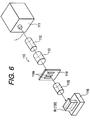
- the head in order to attain the high density of as many as approximately 600 dpi (dots per inch) as the print density, the head should be formed so that 128 liquid flow paths and discharge ports should be arrange at equal intervals in a range of approximately 5.4 mm, respectively. Then, the arrangement pitches become as fine as approximately 42 ⁇ m each. Therefore, for the formation of the liquid flow path grooves and the discharge ports at such fine pitches, it is necessary to use an ultraprecision processing equipment, such as laser processing apparatus, to operate a specific machining in such a high precision.
- an ultraprecision processing equipment such as laser processing apparatus
- a laser processing apparatus of the kind comprises in general the laser oscillator 111 that outputs the laser beam L; the beam shaping optical system 112 that shapes the laser beam L irradiated from the laser oscillator 111 uniformly; the illuminating optical system 113 that irradiates the laser beam L to the mask 114; the laser mask 114 formed with the opening pattern 114a having the light transmitting regions corresponding to the processing configuration of the work piece W; and the projection optical system 115 that projects the image of the opening pattern, which is transmitted through the laser mask 114, onto the processing surface of the work piece W.
- a jig (not shown) to hold the ceiling plate which is the work piece W, and the movable stage 116 that moves this jig.
- the ceiling plate is installed on the movable stage 116 with the jig as the work piece W to form the liquid flow path grooves and the discharge ports on it. Then, the processing surface thereof is positioned on the optical axis of the laser beam L.
- the laser beam L oscillated from the laser oscillator 111 is irradiated onto the processing surface of the ceiling plate through the laser mask 114 to process the liquid flow path grooves and the discharge ports.
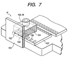
- the liquid jet recording head that uses the ceiling plate which is the work piece W, having the liquid flow path grooves and discharge ports thus formed, is structured as shown in Fig. 7.
- the discharge ports 102 and the liquid flow paths 103 are processed to be formed, and then, the ceiling plate 100 provided with the liquid chamber 104 is bonded with or adhesively joined to the elemental substrate (discharge energy generating means) 107 having a plurality of the discharge energy generating elements (heaters, for example) 106 arranged at given intervals in high precision by the application of ultraprecision etching techniques or the like in the state that each of the liquid flow paths 103 on the ceiling plate 100 is positioned with each of the discharge energy generating element 106, respectively.
- the liquid jet recording head H is manufactured.
- the discharge direction of liquid discharged from the liquid jet recording head is usually controlled by the direction in which each of the discharge ports are processed and formed.
- the laser optical axis is subjected to fine deviation eventually, and the direction of the discharge ports thus processed may be varied in some cases.
- the discharge direction of liquid is varied, accordingly, hence causing the occurrence of such event as the creation of satellites (the smaller liquid droplets than the main liquid droplets which are discharged behind the main liquid droplets to form the images) that may invite the degradation of print quality, among some others that may take place.
- the inspection of the liquid discharge direction and print quality of a liquid jet recording head is usually carried out in general in such a manner that after the recording head is manufactured by bonding the ceiling plate having the discharge ports processed and formed on it with the elemental substrate (discharge energy generating means), liquid (ink) is actually discharged by driving the heaters for the intended inspection of the flying condition of liquid and the impacted point of each of them, and the like. Then, as a result of such inspection, it is determined whether or not the discharge ports thus processed and formed are suitable for the desired print quality in terms of the liquid discharge direction, the creation of satellites, or the like. The result of this determination is fed back to the manufacturing step of the ceiling plate of the recording head, thus correcting the formation angle of the discharge ports. With an inspection method of the kind, it is impossible to allow the result of the inspection, such as deviation of liquid discharge direction, to be reflected on the processing step of the ceiling plate at once so as to improve the production yield of the ceiling plate significantly.
- the present invention is designed in consideration of the problems to be solved for such improvement required for the conventional techniques discussed above. It is an object of the invention to provide a method for inspecting the liquid discharge condition of a liquid jet recording head, which is capable of inspecting the discharge direction of the liquid discharged from the ceiling plate in a short period of time immediately after the discharge ports are formed on the ceiling plate, and also, capable of feeding back the correcting value at once if the liquid discharge angle is deviated from the regular value which is set in advance so as to process and form the discharge ports at the regular angle. It is also an object of the invention to provide an apparatus used for inspecting the discharge condition of a liquid jet recording head.
- the method of the present invention for inspecting the liquid discharge condition of a liquid jet recording head which is structured by assembling a ceiling plate having discharge ports formed on it to discharge liquid and energy generating means to generate energy for discharging liquid, comprises the steps of forcing liquid to flow out from the discharge ports of the ceiling plate after the discharge ports are processed and formed on the ceiling plate, but before the assembled structure is formed; of observing and measuring the flow out condition of the liquid; and of calculating the discharge angle of the liquid.
- the ceiling plate is fixed in the liquid tank immediately after the discharge ports are processed and formed on the ceiling plate, and liquid is injected into the liquid tank to exert pressure on the liquid to force the liquid to flow out from the discharge ports, and that the liquid used is water or the same kind of liquid as the recording liquid actually used for recording images.
- the pressure exerted on the liquid breaks the menisci of the discharge ports of the ceiling plate to form the condition of continuous flow out of the liquid.
- the apparatus of the present invention for inspecting the liquid discharge condition of a liquid jet recording head comprises means for forcing liquid to flow out from the discharge ports of a single ceiling plate after the discharge ports are processed and formed thereon; and an observation and measurement system to observe and measure the flow out condition of the liquid from the discharge ports, and to calculate the discharge angle of the liquid.
- the apparatus for inspecting the liquid discharge condition of a liquid jet recording head, it is preferable to make arrangement so that the apparatus further comprises controlling means for feeding back the result of the calculation of the liquid discharge angle by the observation and measurement system to the processing step of the discharge ports.
- means for forcing the liquid to flow out from the discharge ports of the ceiling plate comprises a liquid tank containing the liquid and having pressure means for exerting a specific pressure on the liquid, and a ceiling plate fixing mechanism in the liquid tank to fix the ceiling plate in it.
- the liquid tank for inspecting the liquid discharge condition of a liquid jet recording head, it is preferable to arrange the liquid tank to be installed on a movable stage, and provided with an opening on the bottom thereof to enable the discharge ports of the ceiling plate to be exposed downward, and also, to enable the ceiling plate fixing mechanism to position the discharge ports of the ceiling plate on the opening and fix the ceiling plate.
- the pressure means of the liquid tank to exert pressure on liquid in the liquid tank by supplying compressed air into the liquid tank or to provided the pressure means of the liquid tank with a vibrating plate having piezoelectric devices on the upper part of the liquid tank so as to exert pressure intermittently by driving the piezoelectric devices.
- liquid is forced to flow out from the discharge ports of the ceiling plate to observe and measure the flow out condition thereof.
- the liquid discharge direction and the liquid discharge angle are inspected by measuring the liquid discharge angle only with the ceiling plate having the discharge ports processed and formed, and if the result of the inspection indicates that the liquid discharge direction and angle are found to be deviated from the regular direction and value, the correcting value is promptly fed back to the processing step of the discharge ports to adjust the formation angle of the discharge ports accordingly for the improvement of the production yield thereof.
- the apparatus of the present invention for inspecting the liquid discharge condition of a liquid jet recording head, it is possible to inspect the liquid discharge direction and the liquid discharge angle promptly and exactly with a simple structure provided with means for forcing liquid to flow out from the discharge ports, which is formed by a liquid tank containing the liquid and having pressure means to exert a specific pressure on the liquid, as well as formed by the ceiling plate fixing mechanism to fix the ceiling plate in the liquid tank, and an observation and measurement system to observe and measure the flow out condition of the liquid from the discharge ports to calculate the discharge angle of the liquid. Further, the apparatus is provided with controlling means to feed back the result of the calculation of the liquid discharge angle by the observation and measurement system to the processing step of the discharge ports promptly. With the structure thus arranged, the correcting value can be fed back to the processing step thereof at once for the significant improvement of the production yield of the ceiling plate that constitutes a recording head.
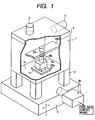
- Fig. 1 is a perspective view which schematically shows the entire structure of an apparatus for inspecting the liquid discharge condition to measure the discharge direction of liquid discharged from the discharge ports of the ceiling plate that constitutes a liquid jet recording head, with a part of the side wall being broken for representation.
- Fig. 2 is a bottom view which shows the apparatus for inspecting the liquid discharge condition represented in Fig. 1, observed from the reverse side of the bottom plate of the liquid tank thereof.
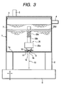
- Fig. 3 is a partly broken cross-sectional view which schematically shows the apparatus for inspecting the liquid discharge condition, which represents the state where liquid is allowed to continuously flow out from the discharge ports of the ceiling plate.
- the apparatus of the present invention for inspecting liquid discharge condition comprises the liquid tank 1 for containing liquid, which is provided with pressure means for exerting specific pressures on the liquid; means for forcing liquid to flow out from the discharge ports of the ceiling plate, which is formed by the ceiling plate fixing mechanism 20 in the liquid tank 1 to fix the ceiling plate 10 that constitutes a liquid jet recording head; the observation measurement system 30 which is installed in the vicinity of the liquid tank 1 to observe and measure the flow-out condition of the liquid that flows out from the discharge portion formed on the ceiling plate 10, and to calculate the liquid discharge direction and the discharge angles; and controlling means (not shown) to feed back the calculated result of the liquid discharge angle by the observation measurement system 30 to the step of processing the discharge ports.
- the liquid tank 1 is installed on the movable stage 9, which is structured to be movable in the top to bottom direction and in the directions to the left and right, through the stand 2.
- the ceiling plate fixing mechanism 20 installed in the interior of the liquid tank 1 comprises the ceiling plate fixing jig 20a to fix the ceiling plate 10; the shaft 20b which is supported movably in the top to bottom direction by the fixing member 20d fixed to both side walls of the liquid tank 1 to face each other, and which is also arranged to hold the ceiling plate fixing jig 20a; and the pressure spring 20c installed around the shaft 20b to bias the ceiling plate fixing jig 20a downward. Also, as shown in Fig. 2 and Fig.
- a cut-off opening 1b to enable the discharge ports 12 of the ceiling plate 10 to be exposed downward when the ceiling plate 10 is fixed by the ceiling plate fixing mechanism 20. Then, on the circumference of the opening 1b, a sealing member 6 is arranged. The sealing member 6 abuts upon the discharge port plate 11 of the ceiling plate 10 to function as a seal to prevent the leakage of liquid in the interior of the liquid tank 1.
- a liquid injection inlet 4 is arranged to inject liquid, and the covering member 3 that airtightly closes the liquid tank 1 is provided with a compressed air supply port 5.
- the arrangement is made so that the compressed air is supplied from the outside through this compressed air supply port 5 to pressure liquid in the interior of the liquid tank 1.
- the liquid tank 1 is formed by the transparent material, such as acrylic resin, to be able to observe the ceiling plate 10 fixed in the interior thereof by use of the observation measurement system 30. Further, since pressure is exerted as described later, the liquid tank is formed with a strength good enough not to be broken by the pressure to be exerted.
- the ceiling plate 10 having the discharged ports 12 processed and formed on it is stacked on the sealing member 6 with the discharge port plate 11 downward so that the discharge ports 12 are placed to face the opening 1b of the bottom plate 1a of the liquid tank 1, and then, fixed to the lower part of the ceiling plate fixing mechanism 20 by use of the ceiling plate fixing jig 20a which is biased by the spring.
- liquid 7 is injected into the liquid tank 1 from the liquid injection port 4. The injection is continued until the water level becomes higher than the ceiling plate 10.
- the liquid 7 it is preferable to use water or the same kind of liquid as the recording liquid used for the actual image recording.
- the liquid used is the one that contains the water soluble dyestuffs containing anion group and water, water soluble organic solvent, and other components (viscosity control agent, pH control agent, antiseptic agent, interfacial active agent or oxidation inhibitor, for example) as required. More specifically, the liquid of the following composition is used: C. I food black - 2 3% glycerin 15% water 82%
- FIG. 4A is a view which schematically shows the state of the ceiling plate 10 being fixed in the interior of the liquid tank 1. Since the discharge angle of liquid is controlled on the basis of the surface (the side AB between both corners A and B of the ceiling plate 10 in Fig. 4A, for example) which is referenced in processing to form the discharge ports, the reference matching is performed before the measurement of the discharged liquid. In other words, both of the corners A and B which become the reference side AB of the ceiling plate 10 are measured, respectively, before the liquid is supplied into the interior of the liquid tank 1.
- the movable stage 9 is adjusted so that the point A of the ceiling plate 10 is placed within the observable range of the observation measurement system 30 as shown in Fig. 4B. Then, the point A is observed by use of the observation measurement system 30. The pixel numbers YA are recorded by the observation measurement system 30 from the upper end to the point A. Subsequently, as shown in Fig. 4C, the movable stage 9 is horizontally moved to make it possible to observe the point B, and the pixel number YB are recorded in the same manner.
- Fig. 4D is a view which schematically shows the state that the water flux 13 is being observed by use of the observation and measurement system.
- the amount of deviation ⁇ X in the left and right directions is obtained from the differences in the pixel numbers in the left and right directions both at the top and bottom ends of the water flux in the observation region.
- the deviated angle ⁇ E against the vertical axis is calculated in the following sequence:
- ⁇ X (XU - XD) ⁇ dX
- the value, which is arrived at by subtracting the deviated angle ⁇ T of the ceiling plate 10 calculated by the expression (2) from the ⁇ E is the discharge angle ⁇ to the axis 0° perpendicular to the reference surface (the side AB in Fig. 4A) of the ceiling plate 10 as given below.
- ⁇ ⁇ E - ⁇ T
- the discharge angle ⁇ thus calculated is the angle at which liquid is discharged from the discharge ports 12 processed and formed on the ceiling plate 10. Then, if this discharge angle ⁇ is deviated from the regular value which has been set in advance, the discharge angle ⁇ thus obtained is immediately fed back to the discharge port laser processing step, hence making it possible to correct it to the regular discharge angle.
- Fig. 5 shows the correction flow of the discharge port formation angle with the feed back of the measured discharge angle to the manufacturing step of the liquid jet recording head.
- the ceiling plate provided with the liquid chamber and others by the injection molding using an appropriate material to form the ceiling plate (S1).
- the laser processing apparatus shown in Fig. 6 the liquid flow paths are processed, at first, by the irradiation of laser on the ceiling plate (S2). After that, using the laser processing apparatus, the discharge ports are processed likewise on the discharge port plate of the ceiling plate (S3).
- the ceiling plate having the laser processed discharge ports on it is placed immediately in the liquid discharge condition inspecting apparatus described above.
- the liquid which is discharged from the discharge ports of the ceiling plate is observed to measure the liquid discharge angle (S4).
- the ceiling plate for which the discharge ports are processed and formed is fixed in the liquid tank of the liquid discharge condition inspecting apparatus in the state where the ceiling plate is not bonded to the discharge energy generating means.
- liquid is supplied to the interior of the liquid tank.
- pressure is exerted on the liquid so as to break the menisci of the discharge ports to form the condition of the continuous flow out of the liquid.
- the discharge direction of the liquid that flows out from the discharge ports is measured to calculate the liquid discharge angle.
- the liquid discharge angle based upon the result of the measurement is compared with the regular discharge angle which is set in advance (S5), and if any deviation from the regular angle is found, the feed back is executed to the discharge port manufacturing step (S3) of the laser processing apparatus in accordance with the amount of the deviation thus found, thus making the correction thereof to the regular discharge angle. Also, if the measured liquid discharge angle is the same as the regular angle, the laser processing of the liquid discharge ports is continued as it is.
- the discharge port formation angle is adjusted to make it possible to process and form the discharge ports in the regular direction.
- the laser machining is applied to the discharge port processing.
- some other means such as press working, it is possible to apply the method and the apparatus of the present invention for inspecting liquid discharge condition.
- a vibrating plate may be installed on the upper part of the liquid tank, and then, it may be arranged to exert pressure in the liquid tank by means of the vibrating plate to be driven by means of piezoelectric devices.
- the driving frequency of the piezoelectric devices is set at the same frequency as the one applied to recording images by use of the liquid jet recording head. With the intermittent driving thereof, the liquid is forced to flow out.
- the algorithm of the angular measurement of the water flux is the same as the embodiment described above. Therefore, the description thereof will be omitted.
- the liquid discharge direction of the discharge ports is inspected immediately after the discharge ports are processed and formed, that is, on the component level.
- the correction value is fed back immediately so as to adjust the discharge formation angle to the regular value, hence making it possible to process and form the discharge ports exactly.
Landscapes
- Engineering & Computer Science (AREA)
- Quality & Reliability (AREA)
- Particle Formation And Scattering Control In Inkjet Printers (AREA)
- Ink Jet (AREA)
- Length Measuring Devices By Optical Means (AREA)
Applications Claiming Priority (2)
| Application Number | Priority Date | Filing Date | Title |
|---|---|---|---|
| JP17807098 | 1998-06-10 | ||
| JP10178070A JPH11348261A (ja) | 1998-06-10 | 1998-06-10 | 液体噴射記録ヘッドにおける液体吐出状態検査方法および液体吐出状態検査装置 |
Publications (2)
| Publication Number | Publication Date |
|---|---|
| EP0963849A2 true EP0963849A2 (de) | 1999-12-15 |
| EP0963849A3 EP0963849A3 (de) | 2001-11-14 |
Family
ID=16042100
Family Applications (1)
| Application Number | Title | Priority Date | Filing Date |
|---|---|---|---|
| EP99110772A Withdrawn EP0963849A3 (de) | 1998-06-10 | 1999-06-04 | Verfahren zur Prüfung des Flüssigkeitsausstosszustands eines Flüssigkeitsstrahlkopfes, und Vorrichtung zur Prüfung des Flüssigkeitsausstosszustands |
Country Status (3)
| Country | Link |
|---|---|
| US (1) | US6421623B1 (de) |
| EP (1) | EP0963849A3 (de) |
| JP (1) | JPH11348261A (de) |
Cited By (3)
| Publication number | Priority date | Publication date | Assignee | Title |
|---|---|---|---|---|
| CN114654888A (zh) * | 2022-03-22 | 2022-06-24 | 东莞市图创智能制造有限公司 | 液体性能测试方法、装置及设备 |
| CN115790456A (zh) * | 2023-02-08 | 2023-03-14 | 中国空气动力研究与发展中心低速空气动力研究所 | 结冰云雾模拟喷嘴雾化锥角测量装置及方法 |
| DE102023131934A1 (de) * | 2023-11-16 | 2025-05-22 | Krones Aktiengesellschaft | Vorrichtung und Verfahren zur Analyse bei einer Direktdampferhitzung eines flüssigen Lebensmittelproduktes |
Families Citing this family (13)
| Publication number | Priority date | Publication date | Assignee | Title |
|---|---|---|---|---|
| JP5596954B2 (ja) * | 2009-10-08 | 2014-09-24 | キヤノン株式会社 | 液体供給部材、液体供給部材の製造方法及び液体吐出ヘッドの製造方法 |
| JP6308989B2 (ja) | 2015-09-30 | 2018-04-11 | キヤノン株式会社 | 液体収納容器及び液体吐出装置 |
| JP2017081083A (ja) | 2015-10-30 | 2017-05-18 | キヤノン株式会社 | 液体吐出装置、ヘッド及び液体充填方法 |
| JP6611564B2 (ja) | 2015-10-30 | 2019-11-27 | キヤノン株式会社 | 液体収納ボトルおよび液体収納ボトルのパッケージ |
| JP6602160B2 (ja) | 2015-10-30 | 2019-11-06 | キヤノン株式会社 | 液体吐出装置及びヘッド |
| JP6700719B2 (ja) | 2015-10-30 | 2020-05-27 | キヤノン株式会社 | 液体吐出装置及びヘッド |
| EP4147873B1 (de) | 2017-10-13 | 2024-12-11 | Canon Kabushiki Kaisha | Element mit pad-elektrode, tintenpatrone, aufzeichnungsgerät |
| JP7267708B2 (ja) | 2017-10-13 | 2023-05-02 | キヤノン株式会社 | パッド電極を有する部材、インクカートリッジ、記録装置 |
| JP7154919B2 (ja) | 2018-09-28 | 2022-10-18 | キヤノン株式会社 | インクカートリッジ |
| JP7224830B2 (ja) | 2018-09-28 | 2023-02-20 | キヤノン株式会社 | パッド電極を有する部材、インクカートリッジ、記録装置 |
| JP7242231B2 (ja) | 2018-09-28 | 2023-03-20 | キヤノン株式会社 | パッド電極を有する部材、記録装置 |
| JP7706986B2 (ja) | 2021-08-16 | 2025-07-14 | キヤノン株式会社 | 液体収容体 |
| CN113720277B (zh) * | 2021-08-25 | 2022-05-10 | 北京科荣达航空科技股份有限公司 | 一种燃油喷嘴雾化角度自动测量机构及自动测量方法 |
Family Cites Families (26)
| Publication number | Priority date | Publication date | Assignee | Title |
|---|---|---|---|---|
| US3886564A (en) | 1973-08-17 | 1975-05-27 | Ibm | Deflection sensors for ink jet printers |
| JPS5448551A (en) * | 1977-09-26 | 1979-04-17 | Ricoh Co Ltd | Ink jet driving circuit |
| US4313124A (en) * | 1979-05-18 | 1982-01-26 | Canon Kabushiki Kaisha | Liquid jet recording process and liquid jet recording head |
| JPS55158971A (en) * | 1979-05-29 | 1980-12-10 | Canon Inc | Detachable mechanism for printing head |
| JPS59224360A (ja) | 1983-05-07 | 1984-12-17 | Fuji Xerox Co Ltd | インクジエツトプリンタ用ドロツプセンサ |
| JPS60219060A (ja) * | 1984-04-17 | 1985-11-01 | Canon Inc | 液体噴射記録装置 |
| US4555712A (en) * | 1984-08-03 | 1985-11-26 | Videojet Systems International, Inc. | Ink drop velocity control system |
| US4748461A (en) * | 1986-01-21 | 1988-05-31 | Xerox Corporation | Capillary wave controllers for nozzleless droplet ejectors |
| JPS62233252A (ja) * | 1986-04-03 | 1987-10-13 | Toshiba Corp | インクジエツト記録装置 |
| JP2643185B2 (ja) | 1987-09-28 | 1997-08-20 | 富士通株式会社 | インクジェットヘッドの検査方法及び検査装置 |
| US4990932A (en) * | 1989-09-26 | 1991-02-05 | Xerox Corporation | Ink droplet sensors for ink jet printers |
| DE69224921T2 (de) * | 1991-01-11 | 1998-08-27 | Canon Kk | Tintenstrahlaufzeichnungsgerät |
| JP2962838B2 (ja) * | 1991-01-18 | 1999-10-12 | キヤノン株式会社 | インクジェット記録装置 |
| US5798778A (en) * | 1992-10-19 | 1998-08-25 | Canon Kabushiki Kaisha | Ink jet head having an ink discharging outlet face and ink jet apparatus provided with said ink jet head |
| ATE225540T1 (de) * | 1993-05-27 | 2002-10-15 | Canon Kk | Verfahren und vorrichtung zur tintenstrahlaufzeichnung |
| US5601737A (en) * | 1993-07-27 | 1997-02-11 | Matsushita Electric Works, Ltd. | Surface treating process involving energy beam irradiation onto multilayered conductor parts of printed circuit board |
| JP3177100B2 (ja) * | 1993-07-29 | 2001-06-18 | キヤノン株式会社 | インクジェットヘッドおよびインクジェット装置ならびに前記ヘッドの製造方法および前記ヘッドの製造装置 |
| JP3352505B2 (ja) | 1993-08-13 | 2002-12-03 | 株式会社リコー | 特徴量および位置検出方法とその装置 |
| US6008914A (en) * | 1994-04-28 | 1999-12-28 | Mitsubishi Denki Kabushiki Kaisha | Laser transfer machining apparatus |
| US5784079A (en) * | 1994-06-30 | 1998-07-21 | Canon Kabushiki Kaisha | Ink jet head and ink jet apparatus on which the ink jet head is mounted |
| US5627571A (en) * | 1994-10-13 | 1997-05-06 | Xerox Corporation | Drop sensing and recovery system for an ink jet printer |
| JP3229146B2 (ja) * | 1994-12-28 | 2001-11-12 | キヤノン株式会社 | 液体噴射ヘッドおよびその製造方法 |
| JPH1072253A (ja) * | 1996-05-30 | 1998-03-17 | Sumitomo Chem Co Ltd | 高密度ito焼結体の製造方法および高密度ito焼結体、並びにそれを用いたitoスパッタターゲット |
| GB9611582D0 (en) * | 1996-06-04 | 1996-08-07 | Thin Film Technology Consultan | 3D printing and forming of structures |
| JP3706715B2 (ja) * | 1996-07-09 | 2005-10-19 | キヤノン株式会社 | 液体吐出ヘッド,液体吐出方法,ヘッドカートリッジ,液体吐出装置,プリントシステムならびに回復処理方法 |
| DE69725067T2 (de) * | 1996-07-09 | 2005-02-17 | Canon K.K. | Flüssigkeitsausstosskopf, Kassette für einen Flüssigkeitsausstosskopf und Flüssigkeitsausstossapparat |
-
1998
- 1998-06-10 JP JP10178070A patent/JPH11348261A/ja active Pending
-
1999
- 1999-06-03 US US09/324,503 patent/US6421623B1/en not_active Expired - Fee Related
- 1999-06-04 EP EP99110772A patent/EP0963849A3/de not_active Withdrawn
Cited By (4)
| Publication number | Priority date | Publication date | Assignee | Title |
|---|---|---|---|---|
| CN114654888A (zh) * | 2022-03-22 | 2022-06-24 | 东莞市图创智能制造有限公司 | 液体性能测试方法、装置及设备 |
| CN115790456A (zh) * | 2023-02-08 | 2023-03-14 | 中国空气动力研究与发展中心低速空气动力研究所 | 结冰云雾模拟喷嘴雾化锥角测量装置及方法 |
| CN115790456B (zh) * | 2023-02-08 | 2023-04-18 | 中国空气动力研究与发展中心低速空气动力研究所 | 结冰云雾模拟喷嘴雾化锥角测量装置及方法 |
| DE102023131934A1 (de) * | 2023-11-16 | 2025-05-22 | Krones Aktiengesellschaft | Vorrichtung und Verfahren zur Analyse bei einer Direktdampferhitzung eines flüssigen Lebensmittelproduktes |
Also Published As
| Publication number | Publication date |
|---|---|
| US6421623B1 (en) | 2002-07-16 |
| EP0963849A3 (de) | 2001-11-14 |
| JPH11348261A (ja) | 1999-12-21 |
Similar Documents
| Publication | Publication Date | Title |
|---|---|---|
| US6421623B1 (en) | Method for inspecting the liquid discharge condition of liquid jet head, and apparatus for inspecting liquid discharge condition | |
| US5657539A (en) | Process for producing an ink jet recording head | |
| US6561633B2 (en) | Ink jet recording head having spacer with etched pressurizing chambers and ink supply ports | |
| US5198054A (en) | Method of making compensated collinear reading or writing bar arrays assembled from subunits | |
| KR100639852B1 (ko) | 액체 분사 헤드 유닛 및 그 제조 방법과 액체 분사 장치 | |
| US7602490B2 (en) | Liquid ejecting head alignment apparatus and liquid ejecting head alignment method | |
| US8800147B2 (en) | Alignment method of liquid-jet head unit | |
| US5748213A (en) | Ink jet head having plural elemental substrates, apparatus having the ink jet head, and method for manufacturing the ink jet head | |
| US6925712B2 (en) | Method of fabricating a liquid-jet head | |
| JP2002079674A (ja) | 液体吐出ヘッドユニット、ヘッドカートリッジおよび液体吐出ヘッドユニットの製造方法 | |
| KR20100065109A (ko) | 유체 분배 어셈블리 | |
| JP4297066B2 (ja) | 液滴吐出装置及び液滴吐出ヘッド | |
| US6729002B1 (en) | Method of producing an ink jet recording head | |
| JP4207074B2 (ja) | アライメント装置及びアライメント方法 | |
| JPH10258386A (ja) | レーザ加工方法および該レーザ加工方法を用いた液体噴射記録ヘッドの製造方法 | |
| JP3126276B2 (ja) | インクジェット記録ヘッド | |
| JPH08318628A (ja) | インクジェット記録ヘッドの製造方法 | |
| US6515255B1 (en) | Processing method of discharge nozzle for liquid jet recording head and manufacturing method of liquid jet recording head | |
| JP3198219B2 (ja) | インクジェット記録ヘッドおよびインクジェット記録装置 | |
| US12036790B2 (en) | Inspection apparatus | |
| JP4591129B2 (ja) | 液滴吐出装置及びパターン形成方法 | |
| US20070064049A1 (en) | Ink jet head nozzle plate manufacturing method, Ink jet head nozzle plate manufacturing apparatus, Ink jet head nozzle plate, Ink jet head, and Ink jet recording apparatus | |
| JP3231195B2 (ja) | インクジェット記録ヘッドの製造方法 | |
| JP2009172880A (ja) | アライメント方法及び液体噴射ヘッドの製造方法 | |
| JP2010172905A (ja) | レーザー加工装置、レーザー加工方法、液体噴射ヘッド及び液体噴射記録装置 |
Legal Events
| Date | Code | Title | Description |
|---|---|---|---|
| PUAI | Public reference made under article 153(3) epc to a published international application that has entered the european phase |
Free format text: ORIGINAL CODE: 0009012 |
|
| AK | Designated contracting states |
Kind code of ref document: A2 Designated state(s): AT BE CH CY DE DK ES FI FR GB GR IE IT LI LU MC NL PT SE Kind code of ref document: A2 Designated state(s): DE ES FR GB IT NL |
|
| AX | Request for extension of the european patent |
Free format text: AL;LT;LV;MK;RO;SI |
|
| PUAL | Search report despatched |
Free format text: ORIGINAL CODE: 0009013 |
|
| RIC1 | Information provided on ipc code assigned before grant |
Free format text: 7B 41J 2/195 A, 7B 41J 29/393 B, 7B 41J 2/125 B |
|
| AK | Designated contracting states |
Kind code of ref document: A3 Designated state(s): AT BE CH CY DE DK ES FI FR GB GR IE IT LI LU MC NL PT SE |
|
| AX | Request for extension of the european patent |
Free format text: AL;LT;LV;MK;RO;SI |
|
| 17P | Request for examination filed |
Effective date: 20020411 |
|
| AKX | Designation fees paid |
Free format text: DE ES FR GB IT NL |
|
| 17Q | First examination report despatched |
Effective date: 20020816 |
|
| STAA | Information on the status of an ep patent application or granted ep patent |
Free format text: STATUS: THE APPLICATION IS DEEMED TO BE WITHDRAWN |
|
| 18D | Application deemed to be withdrawn |
Effective date: 20021227 |