EP0962901A2 - Spielautomat mit Sondermodusanzeige - Google Patents
Spielautomat mit Sondermodusanzeige Download PDFInfo
- Publication number
- EP0962901A2 EP0962901A2 EP99201793A EP99201793A EP0962901A2 EP 0962901 A2 EP0962901 A2 EP 0962901A2 EP 99201793 A EP99201793 A EP 99201793A EP 99201793 A EP99201793 A EP 99201793A EP 0962901 A2 EP0962901 A2 EP 0962901A2
- Authority
- EP
- European Patent Office
- Prior art keywords
- individual
- reel
- prize
- variable display
- game
- Prior art date
- Legal status (The legal status is an assumption and is not a legal conclusion. Google has not performed a legal analysis and makes no representation as to the accuracy of the status listed.)
- Ceased
Links
- 230000015572 biosynthetic process Effects 0.000 title 1
- 238000005070 sampling Methods 0.000 claims description 13
- 238000000034 method Methods 0.000 description 36
- 238000010586 diagram Methods 0.000 description 32
- 241000219109 Citrullus Species 0.000 description 13
- 235000012828 Citrullus lanatus var citroides Nutrition 0.000 description 13
- 241000167854 Bourreria succulenta Species 0.000 description 11
- 235000019693 cherries Nutrition 0.000 description 11
- 239000004973 liquid crystal related substance Substances 0.000 description 6
- 238000010276 construction Methods 0.000 description 3
- 230000000694 effects Effects 0.000 description 2
- 230000000007 visual effect Effects 0.000 description 2
- BYXHQQCXAJARLQ-ZLUOBGJFSA-N Ala-Ala-Ala Chemical compound C[C@H](N)C(=O)N[C@@H](C)C(=O)N[C@@H](C)C(O)=O BYXHQQCXAJARLQ-ZLUOBGJFSA-N 0.000 description 1
- BUZMZDDKFCSKOT-CIUDSAMLSA-N Glu-Glu-Glu Chemical compound OC(=O)CC[C@H](N)C(=O)N[C@@H](CCC(O)=O)C(=O)N[C@@H](CCC(O)=O)C(O)=O BUZMZDDKFCSKOT-CIUDSAMLSA-N 0.000 description 1
- 241000722921 Tulipa gesneriana Species 0.000 description 1
- 238000001514 detection method Methods 0.000 description 1
- 238000003780 insertion Methods 0.000 description 1
- 230000037431 insertion Effects 0.000 description 1
- 230000002093 peripheral effect Effects 0.000 description 1
- 239000011295 pitch Substances 0.000 description 1
Images


Classifications
-
- G—PHYSICS
- G07—CHECKING-DEVICES
- G07F—COIN-FREED OR LIKE APPARATUS
- G07F17/00—Coin-freed apparatus for hiring articles; Coin-freed facilities or services
- G07F17/32—Coin-freed apparatus for hiring articles; Coin-freed facilities or services for games, toys, sports, or amusements
- G07F17/3225—Data transfer within a gaming system, e.g. data sent between gaming machines and users
- G07F17/3227—Configuring a gaming machine, e.g. downloading personal settings, selecting working parameters
-
- G—PHYSICS
- G07—CHECKING-DEVICES
- G07F—COIN-FREED OR LIKE APPARATUS
- G07F17/00—Coin-freed apparatus for hiring articles; Coin-freed facilities or services
- G07F17/32—Coin-freed apparatus for hiring articles; Coin-freed facilities or services for games, toys, sports, or amusements
Definitions
- the present invention relates to a game machine having a function to inform a player of a prize mode determined by a random number lottery.
- a slot machine as a game machine of this kind.
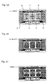
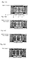
- a general slot machine as shown in Fig. 1A, three reels 3, 4 and 5 are installed in parallel on the rear side of a front panel 2.
- Various patterns are illustrated on the outer circumferences of the individual reels 3 to 5, and the patterns are illuminated by built-in light sources (back lights), not shown, installed at the individual reels and are observed via individual windows 6, 7 and 8 formed at the front panel 2.
- Five prize lines are described in the windows, and the slot machine game is carried out depending upon whether or not a combination of predetermined patterns is set on any of the prize lines.
- the game is started when a player puts a coin into a slot and when the coin is put into the slot, as shown in Fig. 1A, all of the back lights are lighted.
- all of the back lights are extinguished, as shown in Fig. 1B.
- the individual reels 3 to 5 are rotated in response to the operation of a start lever by the player, and the individual windows 6 to 8 are displayed with the patterns which move to rotate in the directions of columns thereof.
- the individual stop buttons installed in correspondence with the individual reels 3 to 5 becomes effective.
- the player operates the individual stop buttons while observing the moving patterns and stops the rotation of the individual reels 3 to 5 thereby to stop and display desired patterns on any of the prize lines.
- the individual reels 3 to 5 stop rotating in response to the operational timings of the individual stop buttons.
- a prizein response tothe combination of patterns is obtained.
- the big hit prize or the medium hit prize is caused when three of patterns "7" or patterns of a predetermined character are set on the prize line.
- a special game of big bonus game (BB game) in the case of the big hit prize or regular bonus game (RB game) in the case of the medium hit prize is carried out, and a large amount of coins can be acquired.
- the small hit prize is caused when a predetermined number of patterns of "cherry” or "bell” are aligned on the prize line, and several coins can be acquired in the small hit prize.
- Fig. 1C shows a case in which patterns "bell" are aligned on a central prize line, and in this case, the back lights are flashed.
- Such prize modes are determined by a lottery of random numbers which is carried out immediately after operating the start lever and has already been determined before the individual reels are operated to stop by the player.
- the lottery of random numbers is executed by prize mode determining means constituted inside of the game machine.
- a display such as a notification lamp installed at the front panel of the machine is lighted, and the player is informed of the fact that the big hit prize is caused by the inner lottery of the machine.
- the rotation of the individual reels is controlled to stop in response to the operation of stopping the buttons by the player, and the prize can be actually experienced by the player when a combination of patterns of the prize determined by the lottery of random numbers is stopped and displayed on the prize line.
- the notification lamp is immediately lighted, and the player is informed of a result of the inner lottery.
- the player is mechanically informed of the result of the inner lottery, as it is, for causing the big hit prize and cannot enjoy the pleasure of searching the result of the inner lottery as in, for example, searching for the "reach spot".
- the "reach spot” means apredetermined combination of patterns which is displayed at the timing of stopping the rotation of the individual reels in the circumstance the big hit prize is caused by the inner lottery.
- a game machine which comprises: prize mode determining means for determining a prize mode of a game by a random number lottery; a variable display device for displaying various patterns variably in a plurality of columns and for displaying a combination of the patterns stationarily in said individual columns in accordance with the prize mode which is determined by said prize mode determining means; variable display starting means for starting the variable display of said variable display device; information means for informing a player, at a predetermined probability, of an information corresponding to the prize mode determined by said prize mode determining means; and notification means for notifying to the player the information in a specific informing mode on a condition in which the information is a predetermined one corresponding to a specific prize mode determined by the prize mode determining means.
- the prize mode determined by the inner lottery is informed to the player at a predetermined probability by the information means. This allows the player to predict the prize mode to a certain extent.
- the result of the inner lottery of causing the specific prize mode is notified to the player by the notification means.
- the result of the inner lottery is not notified by the notification means. Therefore, the player can be informed of the result of the inner lottery causing the specific prize mode through the information informed by the information means even when the result of the inner lottery of causing the specific prize mode is not notified by the notification means. Therefore, the pleasure for searching the occurrence of the specific prize mode is felt in the game from the information of the information means.
- the game machine further comprises variable display stopping means for stopping said variable display for the individual columns.
- the information means informs the player, at a predetermined probability, of an information corresponding to the prize mode determined by said prize mode determining means, in a series of flow of the game from the start of said variable display by said variable display starting means to the end of one game stopped by stopping said variable display by said variable display stopping means, and the notification means notifies to the player the information by the specific informing mode on a condition in which the information by the information means is one corresponding to the specific prize mode determined by the prize mode determining means and the predetermined information informed to the player at a probability of 100 %.
- the prize mode determined by the inner lottery is informed to the player at a predetermined probability by the information corresponding to the prize mode through a series of flow of the game. This allows the player to predict the prize mode to a certain extent with the information mode according to the progress of the game.
- the result of the inner lottery of causing the specific prize mode is notified to the player by the notification means.
- the specific prize mode is informed at a probability smaller than 100 %, that is, in case even when the specified prize mode is caused by the inner lottery, the specific prize mode may not necessarily be informed, the result of the inner lottery is not notified by the notification means. Therefore, the player can be informed of the result of the inner lottery causing the specific prize mode through the information informed through a series of flow of the game by the information means even when the result of the inner lottery of causing the specific prize mode is not notified by the notification means. Therefore, also in this case, the pleasure for searching the occurrence of the specific prize mode is felt in the game from the information of the information means.
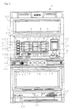
- Fig. 2 is a front view of a slot machine 1 according to this embodiment.
- Three reels 3, 4 and 5 constituting a variable display device are rotatably installed on the rear side of a front panel 2 of the slot machine 1.
- Columns of symbols comprising plurality of kinds of patterns (hereinafter, referred to as the "symbols") are illustrated on the outer circumferences of the individual reels 3, 4 and 5.
- Three of the symbols are observed via each of display windows 6, 7 and 8 at the front face of the slot machine 1.
- a slot 9 into which a player inserts coins is installed on the lower right side of the display windows 6, 7 and 8.
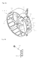
- the individual reels 3 to 5 are constituted as a rotating reel unit shown in Fig. 3 and are attached to a frame 51 through brackets 52.
- Each of the reels 3 to 5 is constituted by pasting a reel band 54 on the outer circumference of a reel drum 53.
- the aforementioned symbol column is on the outer circumference of the reel band 54.
- each of the brackets 52 is installed with a stepping motor 55, and the individual reels 3 to 5 are rotated by the drive of the motor 55.
- FIG. 4A shows the structure of each of the reels 3 to 5.
- a lamp case 56 is installed inside of the reel drum 53 on the rear side of the reel band 54, and back lamps 57a, 57b and 57c are respectively attached to the three chambers of the lamp case 56.
- the back lamps 57a, 57b and 57c are mounted on a board 58, which is attached to the rear side of the lamp case 56.
- a photosensor 59 is attached to the bracket 52. The photosensor 59 detects a shield plate, as installed to the reel drum 53, to pass through the photosensor 59 as the reel drum 53 rotates.
- the individual back lamps 57a, 57b and 57c are individually controlled and lighted by a later-described lamp drive circuit 48. By lighting the individual back lamps 57a, 57b and 57c, three symbols on the front side of the back lamps 57a, 57b and 57c are individually lighted from the rear side among symbols illustrated on the reel bands 54 so that they are projected on each of the display windows 6 to 8.
- these display windows 6 to 8 shown in Fig. 2 are described with prize lines of horizontal three lines (including a central line L1, and upper and lower lines L2A and L2B) as well as two skew lines (including a skew right downward line L3A and a skew right upward line L3B).
- prize lines of horizontal three lines including a central line L1, and upper and lower lines L2A and L2B
- two skew lines including a skew right downward line L3A and a skew right upward line L3B.
- circular marks in Figs. 5A, 5B and 5C represent symbols illustrated on the respective reels 3 to 5.
- the effectiveness of the prize line is displayed to the player by lighting effective line display lamps 23 (as should be referred to Fig. 2) arranged at the end portions of the individual prize lines.
- a 1BET switch 10, a 2BET switch 11 and a maxBET switch 12 are installed on the lower left side of the display windows 6 to 8.
- a credit number display unit 13 is constructed by seven segment LEDs (Light Emitting Diodes) in accordance with the number of digits of a displayed numerical value, and displays the number of coins currently credited.
- a credit/pay-out switch (C/P switch) 14 and a start lever 15 are installed on the lower side of the BET switches 10 to 12, and stop buttons 16, 17 and 18 are installed at a central portion of the device on the right side of the start lever 15. By operating the push button of the C/P switch 14, a play credit/pay-out can be switched.
- the start lever 15 constitutes variable display starting means for starting the rotation display of the individual reels 3 to 5 so that the rotations of the reels 3, 4 and 5 are started altogether when the start lever 15 is operated.
- the stop buttons 16, 17 and 18 constitute variable display stopping means for stopping the rotation display of the individual reels 3, 4 and 5 for each column and are arranged to correspond to the reels 3, 4 and 5, respectively.
- the operation of the individual stop buttons 16 to 18 is made effective to stop the rotation of the individual reels 3 to 5 in response to the pushing operation of the player.
- a sound emitting hole 19 and a coin tray 20 are installed on the lower side of the front face of the slot machine 1.
- the sound emitting hole 19 is provided for emitting the sound, as generated from a speaker housed inside of the device, to the outside.
- the coin tray 20 is provided for storing the coins paid out from a coin outlet 21.
- a prize display portion 22 for indicating how many coins are to be paid out to each prize is installed on the upper side of the front face of the slot machine 1.
- a liquid crystal display unit 24 is installed at the front panel 2 on the right side of the individual reels 3, 4 and 5.
- the liquid crystal display unit 24 is a display device for displaying the rotation of the individual reels 3, 4 and 5, displaying the history of a game or carrying out a representation in a bonus game.
- a notification lamp 25 is installed on the front panel 2 right under the individual reels 3, 4 and 5. The notification lamp 25 is lighted, when the inner hit flag of BB or RB game is erected so that a later-described predetermined condition is established, and notifies the player of the fact that the bonus game is hit by the lottery inside of the machine.
- Fig. 6 shows a circuit construction including a control unit for controlling the operation of a game process in the slot machine 1 of the embodiment, and peripheral devices (e.g., actuators) electrically connected with the control unit.
- control unit for controlling the operation of a game process in the slot machine 1 of the embodiment
- peripheral devices e.g., actuators
- the control unit is constituted by a microcomputer (as will be referred to as the "micon") 30 as a major component, and additional circuits for random number sampling.
- the micon 30 is constituted to include a CPU 31, a ROM 32 and a RAM 33 as storage means.
- the CPU 31 is connected with a clock pulse generating circuit 34 and a divider 35 for generating reference clock pulses, a random number generator 36 acting as random number generating means for generating random numbers in a constant range, and a random number sampling circuit 37 acting as random number sampling means for sampling an arbitrary random number among the generated random numbers.
- the stepping motor 55 for driving each of the reels 3, 4 and 5 to rotate, a hopper 38 for containing coins, the liquid crystal display unit 24, a speaker 39, the back lamps 57a, 57b and 57c and the notification lamp 25.
- These actuators are respectively driven by a motor drive circuit 40, a hopper drive circuit 41, a display drive circuit 42, a speaker drive circuit 43 and the lamp drive circuit 48.
- These drive circuits 40 to 43 and 48 are connected with the CPU 31 through an I/O port of the micon 30.
- the stepping motor 55 is excited in a 1 or 2 phase by the motor drive circuit 40 and is rotated by one turn when it is fed with a drive signal of 400 pulses.
- a start switch 15S for detecting an operation of the start lever 15, a coin input sensor 9S for detecting a coin inserted through the coin inserting slot 9 and the aforementioned C/P switch 14.
- the photosensor 59 and a reel position detecting circuit 44 for detecting the rotational positions of the individual reels 3, 4 and 5 in response to an output pulse signal coming from the photosensor 59.
- the photosensor 59 detects the shield plate 60 at each rotation of the individual reels 3, 4 and 5 to generate a reset pulse.
- This reset pulse is transmitted to the CPU 31 through the reel position detecting circuit 44.
- the RAM 33 is stored with numerical values corresponding to the rotational positions in a range of one rotation in respect of the individual reels 3 to 5.
- the CPU 31 clears the numerical values, as established in the RAM 33, to "0". By this clearing action, a deviation, as caused between the display of movement of each symbol and the rotation of each stepping motor 55, is resolved at each rotation.
- the reel stop signal circuit 45 generates signals for stopping the corresponding ones of the reels 3, 4 and 5 when the stop buttons 16, 17 and 18 are pushed.
- a coin detecting unit 47 counts the number of coins paid out from the hopper 38, and the pay completion signal generating circuit 46 outputs a signal for informing the completion of the pay-out of coins to the CPU 31 when the counted value of actually paid-out coins, as inputted from the coin detecting unit 47, reaches the data of a predetermined number of prizes.
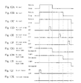
- the speaker 39, the speaker drive circuit 43 and the micon 30 constitute sound emitting means for generating either of two kinds of game starting sounds 1 and 2 as the effect sound when the rotation display of the individual reels 3 to 5 is started by the start lever 15.
- the kind of the game starting sound to be generated by the sound emitting means is selected according to the kind of the prize mode, as will be described hereinafter.
- Fig. 7A The timing at which each game starting sound 1 or 2 is emitted is illustrated in Fig. 7A, and this sound is outputted for a duration tl just after the prize mode lottery timing illustrated in Fig. 7E.
- the start lever 15 has to be operated at a time interval of t2, e.g., 4.1 seconds so that a reel rotation inhibit sound is outputted at a timing, as illustrated in Fig. 7B, from the speaker 39 when a next lever operation is carried out within the time period t2 from the previous start lever operation, as illustrated in Fig. 7D.
- Fig. 7C illustrates the rotational state of the reel which will stop finally in the previous game.
- the lamp drive circuit 48, the back lamps 57a to 57c and the micon 30 constitute connective staging means for staging the displays of the individual reels 3 to 5 successively in one of four kinds of display modes in connection with the stop of the rotational display of the individual reels 3 to 5 by the operation of the individual stop buttons 16 to 18.
- the display modes to be staged by this connective staging means are selected according to the kinds of the prize modes, as will be described hereinafter.
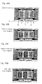
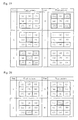
- Figs. 8, 9, 10 and 11 illustrate first, second, third and fourth display modes to be staged by the connective staging means.
- the same portions of these Figures as those of Fig. 2 are designated by the same notations, and their description will be omitted.
- the first connective staging mode designates "no reel lamp extinguishment", in which the connective staging means lights all the back lamps 57a to 57c during the rotation of the individual reels 3 to 5, as illustrated in Fig. 8A.
- the first stop button 16 is operated to stop the rotation of the first reel 3
- the individual back lamps 57a to 57c of the first reel 3 are kept lighted, as illustrated in Fig. 8B.
- the rotations of the second and third reels 4 and 5 are successively stopped by operating the second and third stop buttons 17 and 18, the individual back lamps 57a to 57c of the second and third reels 4 and 5 are also kept lighted, as illustrated in Figs. 8C and 8D.
- the second connective staging mode designates "reel lamp extinguishing pattern 1", in which the connective staging means lights all the back lamps 57a to 57c during the rotation of the individual reels 3 to 5, as illustrated in Fig. 9A.
- the connective staging means lights all the back lamps 57a to 57c during the rotation of the individual reels 3 to 5, as illustrated in Fig. 9A.
- the first stop button 16 is operated to stop the rotation of the first reel 3
- the individual back lamps 57a to 57c of the first reel 3 are extinguished, as illustrated in Fig. 9B.
- the rotations of the second and third reels 4 and 5 are successively stopped by operating the second and third stop buttons 17 and 18, furthermore, the individual back lamps 57a to 57c of the second and third reels 4 and 5 are also kept lighted, as illustrated in Figs. 9C and 9D.
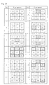
- the third connective staging mode designates "reel lamp extinguishing pattern 2", in which the connective staging means lights all the back lamps 57a to 57c during the rotation of the individual reels 3 to 5, as illustrated in Fig. 10A.
- the connective staging means lights all the back lamps 57a to 57c during the rotation of the individual reels 3 to 5, as illustrated in Fig. 10A.
- the first stop button 16 is operated to stop the rotation of the first reel 3
- the individual back lamps 57a to 57c of the first reel 3 are extinguished, as illustrated in Fig. 10B.
- the individual back lamps 57a to 57c of the second reel 4 are extinguished, as illustrated in Figs. 10C.
- the rotation of the third reel 5 is stopped by operating the third stop button 18, furthermore, the individual back lamps 57a to 57c of the third reel 5 is are kept lighted, as illustrated in Figs. 10D.
- the fourth connective staging mode designates "reel lamp extinguishing pattern 3", in which the connective staging means lights all the back lamps 57a to 57c during the rotation of the individual reels 3 to 5, as illustrated in Fig. 11A.
- the connective staging means lights all the back lamps 57a to 57c during the rotation of the individual reels 3 to 5, as illustrated in Fig. 11A.
- the first stop button 16 is operated to stop the rotation of the first reel 3
- the individual back lamps 57a to 57c of the first reel 3 are extinguished, as illustrated in Fig. 11B.
- the timing charts illustrated in Figs. 12A to 12K indicate the timings of the individual portions when the individual back lamps 57a to 57c are controlled to light according to the fourth connective staging mode.
- the start lever 15 is operated at the timing illustrated in Fig. 12J
- the later-described prize mode determinating lottery operation is carried out at the timing illustrated in Fig. 12K, and the individual reels 3, 4 and 5 successively rotate altogether, as illustrated in Figs. 12A, 12B and 12C.
- the first reel stop button 16 the second reel stop button 17 and the third reel stop button 18 are operated in this order, as shown in Figs. 12D, 12E and 12F, the first reel 3, the second reel 4 and the third reel 5 are stopped at the respective timings, as illustrated in Figs.
- the reel stop control is conveniently explained in this embodiment in case the first reel stop button 16, the second reel stop button 17 and the third reel stop button 18 are operated in this order, as illustrated in Figs. 12D, 12E and 12F, to stop the first reel 3, the second reel 4 and the third reel 5 in this order, as illustrated in Figs. 12A, 12B and 12C.
- the order of stopping the individual reels 3 to 5 should not be limited thereto but may be exemplified in a random operating order in which the first reel stop button 16, the third reel stop button 18 and the second reel stop button 17 are stopped in the recited order.
- the lamp drive circuit 48, the back lamps 57a to 57c and the micon 30 also constitute stop staging means for staging the displays of the individual reels 3 to 5 in one of the ten kinds of display modes when all the rotational displays of the individual reels 3 to 5 are stopped.
- the display modes to be staged by this stop staging means are selected according to the kinds of the prize modes, as will be described hereinafter.
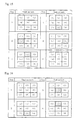
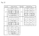
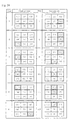
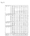
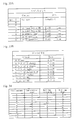
- Figs. 13 to 26 show one example of ten kinds of stop display modes to be staged by the stop staging means.
- Notations (1), (2) and (3) in the column "flashing pattern" of those Figures designate the individual back lamps 57a of the reels 3, 4 and 5; notations (4), (5) and (6) the individual back lamps 57b of the reels 3, 4 and 5; and notations (7), (8) and (9) the back lamps 57c of the reels 3, 4 and 5.
- the hatched portions indicate a lamp lighted state, and the blank portions indicate the lamp extinguished state.
- the " step " columns of the Figures indicate the elapsing stages of time so that the individual back lamps 57a to 57c are lighted or extinguished, as shown, at every stage.
- the display mode of the "no reel lamp flashing" or the first stop display mode is not shown, but the stop staging means keeps all the back lamps 57a to 57c of the individual reels 3 to 5 lighted when all the reels 3 to 5 are stopped but does not control them to flash.
- the second stop display mode shown in Fig. 13 is that of the "reel lamp flashing pattern 1", and the stop staging means extinguishes all the back lamps 57a of the individual reels 3 to 5, as shown at a stage 1 in Fig. 13, when all the reels 3 to 5 are stopped.
- the stop staging means lights the individual back lamps 57a to 57c of the first reel 3 and then lights the individual back lamps 57a to 57c of the second reel 4, as shown at a stage 3.
- the stop staging means lights the individual back lamps 57a to 57c of the third reel 5 and then lights all the back lamps 57a to 57c of the individual reels 3 to 5, as shown at a stage 4.
- the third stop display mode shown in Fig. 14 is that of the "reel lamp flashing pattern 2".
- the stop staging means extinguishes at first all the back lamps 57a of the individual reels 3 to 5, as shown at the stage 1 in Fig. 14, when all the reels 3 to 5 are stopped. Successively, the stop staging means lights the individual back lamps 57b of the first reel 3 and the third reel 5, as shown at the stage 2, and then lights the back lamps 57a of the first reel 3 and the back lamps 57c of the third reel 5, as shown at the stage 3.
- the stop staging means lights the individual back lamps 57a and 57c of the second reel 4, as shown at the stage 4, and then lights the back lamps 57c of the first reel and the back lamps 57a of the third reel 5, as shown at a stage 5. Finally, the stop staging means lights the back lamps 57b of the first reel 3 and the back lamps 57b of the third reel 5, as shown at a stage 6.
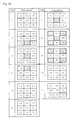
- the fourth stop display mode shown in Fig. 15 is that of the "reel lamp flashing pattern 3".
- the stop staging means extinguishes at first all the back lamps 57a of the individual reels 3 to 5, as shown at the stage 1 in Fig. 15, when all the reels 3 to 5 are stopped. Successively, the stop staging means lights the back lamps 57b of the first reel 3, as shown at the stage 2, and then lights the back lamps 57a of the second reel 4, as shown at the stage 3. After this, the stop staging means lights the back lamps 57c of the second reel 4, as shown at the stage 4, and then lights the back lamps 57b of the third reel 5, as shown at the stage 5. Finally, the stop staging means extinguishes all the back lamps 57a to 57c of the individual reels 3 to 5, as shown at the stage 6.
- the fifth stop display mode of the stages 1 to 13, as shown in Figs. 16 and 17, are those of the "reel lamp flashing pattern 4"
- the sixth stop display mode of the stages 1 to 11, as shown in Fig. 18, are those of the "reel lamp flashing pattern 5"
- the seventh stop display mode of the stages 1 to 6, as shown in Fig. 19, are those of the "reel lamp flashing pattern 6”
- the eighth stop display mode of the stages 1 to 21, as shown in Figs. 20, 21 and 22, are those of the "reel lamp flashing pattern 7".
- the ninth stop display mode of the stages 1 to 12, as shown in Fig. 23, are those of the "reel lamp flashing pattern 8”
- the tenth stop display mode of the stages 1 to 28, as shown in Figs. 24, 25 and 26, are those of the "reel lamp flashing pattern 9".
- the individual back lamps 57a to 57c of the individual reels 3 to 5 are controlled to flash by the stop staging means in accordance with the reading method similar to that of the reel lamp flashing patterns of Figs. 13 to 15.
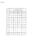
- the ROM 32 is stored with a game processing procedure to be executed in the slot machine 1 as a sequence program, as well as a prize probability table, a symbol table, a prize symbol combination table, a demonstration lottery table selecting table, a demonstration lottery table, and so on, which are individually classified from one another.
- the prize probability table constitutes random number classifying means for classifying the random numbers, as sampled by the sampling circuit 37 into the individual prize modes, and stores the data for classifying the random numbers in constant ranges, as generated by the random number generator 36, into the individual prize modes.
- This prize probability table is constructed, as shown in Fig. 27. Notations al to a3, bl to b3, cl to c3, dl to d3, el to e3, f1 to f3, and g1 to g3 in Fig. 27 designate the preset numerical value data which are used for classifying the random numbers, as sampled by the sampling circuit 37, into the individual prize modes. According to the data, there are used combinations of the individual numerical values of "al to gl" when the number of inputted coins is one, “a2 to g2" when the number is two, and "a3 to g3" when the number is three.
- the prize mode is determined depending upon which numeral value range the sampled random number value belongs to, and is represented by a total of eight kinds of hit flags including "blank" and "replay".
- the random number generator 36, the sampling circuit 37, the prize probability table and the micon 30 constitute prize mode determining means.
- the various hits are made under probabilities according to the data setting in the prize probability table. Therefore, the various hits are not extremely controlled by the skill of the player, and a total coin pay rate in, for example, the business hours of one day is maintained substantially constant.
- the symbol table is conceptionally illustrated in Fig. 28.
- the symbol table corresponds the rotational positions of the individual reels 3 to 5 to symbols, and represents the symbol columns by the notations.
- the symbol table is stored with symbol codes corresponding to the code numbers. These code numbers are successively provided at constant rotational pitches of the reels 3 to 5 with reference to the rotational position for generating the aforementioned reset pulse.
- the symbol codes designate the symbols which are provided to correspond to the individual code numbers.
- the prize symbol combination table is stored with the symbol codes of the individual prize symbol combinations which are displayed on the prize display portion 22, the symbol codes of the symbol combinations constituting the "reach spot" indicatingto the player that the flags for causing a specific game are established, the prize determination codes representing the individual prizes, the number of coins for the prize, and so on.
- the prize symbol combination table is referred to, when the first reel 3, the second reel 4 and the third reel 5 are controlled to stop and when the prize is confirmed after stopping all the reels.
- the demonstration lottery table selecting table and the demonstration lottery table constitute information mode selecting means for selecting the combination of the kinds of the game starting sounds, the kinds of the connective display modes and the kinds of the stop display modes in accordance with the prize mode which is determined by the aforementioned prize mode determining means.
- the information mode selecting means, the sound emitting means, the connective staging means and the stop staging means constitute information means for informing the player of a prize mode at a predetermined probability through a series of flow of the slot machine game.
- the selection lottery operation of the information mode by the information mode selecting means is timed successive to the prize mode probability lottery timing, as shown in Fig. 7E or 12K.
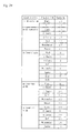
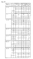
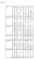
- the demonstration lottery table selecting table shown in Fig.29 is provided for selecting the demonstration lottery tables of No. 0 to No. 17 shown in Figs. 30 to 32 from a game state and a hit flag.
- the game state becomes clear by referring to a storing region of the game level status (GMLVSTS) shown in Fig. 33A.
- the GMLVSTS storing region is stored as data of 1 byte in the RAM 33.
- the game state is stored at 0 to 4 bits, and the game state, as turned ON by setting the data to 1, is one of that time.
- RB signifies the aforementioned regular bonus game and in this RB game, a bonus game in which a plurality of times of high prize games constitute one set can be carried out once.
- the "RB operation” represents a state of game in the RB game, and either a blank or JAC hit is caused.
- BB signifies the aforementioned big bonus game, and in the BB game, sets of general games and the aforementioned bonus game can be carried out by a plurality of times.
- the " BB operation” signifies the game state in the BB game. Furthermore, the “general game” is a state of game in which no prize is caused.
- the "inner hit of RB” and the “inner hit of BB” represent a general game state, in which although the RB hit flag or the BB hit flag is erected, a predetermined prize combination of symbols is neither stopped to display nor the game enters the RB game or the BB game yet.
- the hit flag becomes clear by referring to the storing region of the flag counter (FLGCTR) shown in Fig. 33B.
- This FLGCTR storing region is also stored as data of 1 byte in the RAM 33.
- the hit flag of that time is indicated by 1 byte data of 00 to 07 of hexadecimal digits.
- the demonstration lottery table at that time is No. 7 demonstration lottery table from the demonstration lottery table selecting table.
- the demonstration lottery table of No. 7 is shown in Fig. 31, and the kind of the game starting sound, the kind of the pattern of extinguishing the back lamps of the reels and the kind of the pattern of flashing the back lamps of the reels are selected by the later-described lottery, using the lottery values indicated by the table.
- the kind of the pattern of extinguishing the reel lamps corresponds to that of the connective display mode, and the kind of the pattern of flashing the reel lamps correspond to that of the stop display mode.
- the combination of the column of a lottery value 18 is selected from the No. 7 demonstration lottery table, for example, the game starting sound is 2, the reel lamp extinguishing pattern is the pattern 3, and the reel lamp flashing pattern is the pattern 9.
- the demonstration lottery table of No. 7 When a combination of a column of a lottery value 55 is selected by the demonstration lottery table of No. 7 in the aforementioned case in which the game level status is the general game and in which the flag counter is the inner hit of BB, furthermore, the game starting sound is 1, the reel lamp extinguishing pattern is no extinguishment, and the reel lamp flashing pattern is no flash.
- the data of bit 2 of the GMLVSTS is set to 1 and when the data of the FLGCTR is 00H, on the other hand, the game state is the general game, and the hit flag becomes a blank.
- the demonstration lottery table at that time becomes the demonstration lottery table of No. 0 from the demonstration lottery table selecting table.
- the demonstration lottery table of No. 0 is shown in Fig. 30.
- the staging mode combination at that time are also that the game starting sound is 1, that the reel lamp extinguishing pattern is no extinguishment, and that the reel lamp flashing pattern is no flash. That is, even in the game establishing different hit flags, depending on a value of a random number for determining a pattern for informing a prediction, the same prediction informing pattern may appear.
- the kind of a hit flag is informed to the player in accordance with the combination of staging modes, which is determined by the game state at that time, and the reliability is not uniform.
- the probability of informing a prediction of the RB or BB flag hit in the inner hit of the RB or the inner hit of the BB is previously determined to a predetermined value in a range of 0 to 100 %.
- Fig. 34 shows eleven kinds of determined patterns in which the informing operation of predicting the RB or BB flag hit is carried out at a probability of 100 % in the inner hit of the RB or the inner hit of the BB. That is, the prediction information of the combination of the individual staging modes of the staging mode combination of the game starting sound, the reel lamp extinguishing pattern and the reel lamp flashing pattern appears in the inner hit of the RB or the inner hit of the BB, as shown in Fig. 34, only when the RB or BB flag is hit but not when the RB or BB flag is not hit.
- the table of the pattern of the combination of the staging modes, as shown in Fig. 34, in which the RB or BB game is determined, is also previously stored in a predetermined region of the ROM 32.
- the micon 30, the lamp drive circuit 48 and the notification lamp 25 constitute notification means for notifying the information to the player by the display of a displayer (or the notification lamp 25 in the embodiment) when the information corresponding to a specific prize mode (e.g., the inner hit of the RB or BB in the embodiment) determined by the prize mode determining means is informed to the player by the notification means at the probability of 100 %.
- a specific prize mode e.g., the inner hit of the RB or BB in the embodiment
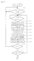
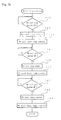
- Figs. 35 and 36 are flowcharts showing an outline of the game process.
- Step 101 of Fig. 35 it is determined by the CPU 31 (as should be referred to Step 101 of Fig. 35) whether or not a coin BET has been carried out.
- the answer is "YES" when a coin is inserted into the coin slot 9 so that a detection signal is inputted from the coin sensor 9S or signals are inputted from the BET switches 10, 11 and 12.
- all the back lamps 57a, 57b and 57c built in the first reel 3, the second reel 4 and the third reel 5 are lighted by the control of the lamp drive circuit 48 by the CPU 31.
- Step 102 it is determined (at Step 102) whether or not a start signal has been inputted from the start switch 15S by operating the start lever 15.
- the determination of prize is carried out by the prize mode determining means (at Step 103).
- the prize determination is made by determining which prize group in the prize probability table (as should be referred to Fig. 27) one random number generated in the random number generator 36 and specified by the sampling circuit 37 belongs to.
- data of either one of eight kinds of the "blank”, the “2 cherries”, the “4 cherries”, the “bell”, the “watermelon”, the “replay”, the "RB” and the “BB” are written and temporarily latched in the aforementioned FLGCTR (as should be referred to Fig. 33B).
- the informing selection lottery operation of the prize mode is carried out (at Step 104).
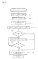
- the informing selection lottery operation of the prize mode is carried out according to a flowchart shown in Fig. 37.
- the GMLVSTS region (as should be referred to Fig. 33A) stored in the RAM 33 is referred to, and the game state at that time is grasped (at Step 201 in Fig. 37).
- the data latched in the FLGCTR are referred to, and the kind of the hit flag is grasped (at Step 201).
- either one of the demonstration lottery tables of No. 0 to No. 17 is selected by referring to the demonstration lottery table selection table (as should be referred to Fig. 29) from the game state at that time and the kind of the hit flag (at Step 203).
- a count value C is sampled at an arbitrary timing from a counter for refreshing the RAM 33 at constant time intervals (at Step 204).
- the demonstration lottery table of No. 7 is selected, and the selection lottery operation of the staging mode at this time is carried out, as follows.
- a value 50 is sampled as the refresh counter value C at Step 204
- the combination of the staging modes of the column of the lottery value 55 that is, the combination of the staging modes of the game starting sound 1, no reel lamp extinguishment and no reel lamp flashing is selected to the prediction informing mode.
- a demonstration lottery table of No. 16 is selected (as should be referred to Fig. 29), and the selection lottery operation of the staging mode combination at this occasion is carried out, as follows.
- the combination of the staging modes of the column of the lottery value 32 that is, the combination of the staging modes of the game starting sound 1, the reel lamp extinguishing pattern 3 and the reel lamp flashing pattern 3 is selected as the prediction informing mode.
- a game starting sound emitting operation is carried out (at Step 105 of Fig. 35). This operation is carried out according to the staging mode combination which is selected by the aforementioned information selection lottery operation, and the speaker drive circuit 43 is controlled by the CPU 31 in accordance with the kind of the game starting sound so that one of the game starting sound 1 and 2 is outputted from the speaker 39.
- These game starting sounds 1 and 2 are emitted from the sound emitting hole 19 formed in the lower portion of the front face of the machine so that they can be grasped by the auditory sense of the player.
- the game starting sound 1 is emitted.
- the watermelon is hit in the internal hit of the BB so that the staging mode combination of the column of the lottery value 32 of the demonstration lottery table No. 16 is selected, as described hereinbefore, the game starting sound 1 is emitted.
- Step 106 the rotating operation of the first reel 3, the second reel 4 and the third reel 5 is carried out (at Step 106), the individual reels 3, 4 and 5 start rotating simultaneously.
- Step 107 the stop control of the individual reels 3, 4 and 5 is carried out (at Step 107).
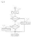
- An outline of the reel stop control operation is shown by a flowchart in Fig. 38.
- the operation of the individual stop buttons 16 to 18 by the player is detected by the CPU 31 through the reel stop signal circuit 45, as described hereinbefore.
- the stop control operation of the first reel 3 is carried out (at Step 122). That is, at a time point at which the first reel stop button 16 is operated by the player, the number of drive pulses supplied to the stepping motor 55 of the first reel 3 is read from the RAM 33 and is made to correspond to the rotational position of the first reel 3.
- the rotational position of the first reel 3 is known, three symbols appearing in the observation window 6 are grasped as symbol codes by referring to the symbol table (as should be referred to Fig. 28).
- the hit flag of the big hit when the hit flag of the big hit is erected, it is checked whether or not there is the symbol constituting the big hit is present on the effective prize line of the observation window 6.
- the hit flag of the medium hit or the small hit when the hit flag of the medium hit or the small hit is erected, it is checked whether or not there is the symbol constituting the medium hit or the small hit is present on the effective prize line of the observation window 6.
- the CPU 31 immediately stops the first reel 3. Considering that the first reel 3 cannot be stopped instantaneously, furthermore, the processing may be carried out at several Steps before the rotational position of the reel.
- control operation of the back lamps of the first reel is carried out (at Step 123).
- the control operation is carried out in accordance with the combination of the staging modes on the demonstration lottery table selected by the aforementioned informing selection lottery operation at Step 104, and the back lamps 57a to 57c built in the first reel 3 are controlled to light in accordance with the selected reel lamp extinguishing pattern.
- the individual back lamps 57a to 57c of the first reel 3 are not extinguished, as shown in Fig. 8B.
- the individual back lamps 57a to 57c of the first reel 3 are extinguished, as shown in Fig. 11B.
- the second reel 4 and the third reel 5 are rotating so that the individual back lamps 57a to 57c of the individual reels 4 and 5 are lighted.
- Step 124 it is detected (at Step 124) whether or not the stop button 17 of the second reel 4 is operated and when the ON operation of the stop button 17 is detected, the stop control operation of the second reel 4 is carried out (at Step 125).
- this stop control operation in a state of rotating the second reel 4, firstly, assuming that symbols of 21 ways having the code numbers of 0 to 20 are stopped on the prize line L1 at the center of the observation window 7, a combination with the symbol of the first reel 3 which has already been stopped on the effective prize line is read. Further, in respect of the third reel 5, a rotation code representing that the third reel 5 is rotating is read. Although the second reel 4 is also rotating, furthermore, its rotation code is not read because it is assumed that the second reel 4 is to be stopped by the aforementioned operation.
- the aforementioned prize symbol combination table is referred to, in respect of the symbol determined by stopping the first reel 3, and what prize may be caused on the effective prize line when the second reel 4 is stopped at the 21 ways of rotational positions is successively determined.
- the symbol combination pattern at this time is checked imagining the 21 ways of the stop positions of the second reel 4.
- the second reel 4 is stopped at a code number "5", for example, as shown in Fig. 39B, the combination of symbols on the individual prize lines L1, L2A, L2B, L3A and L3B is as shown in Fig. 39C.
- An arrow mark of the third reel 5 designates a rotation code indicating that the reel is rotating, and depending on the position of stopping the third reel, there are possibilities of causing a big hit prize of "A-A-A” on the prize line L1 and a small hit prize of "E-E-E” on the prize line L2B.
- a prediction flag of the big hit and a prediction flag of the small hit are set. The presence or absence of the prediction flag is checked with respect to all the code numbers of the second reel 4, and these data are written in the RAM 33.
- the prediction flag data written in the RAM 33 are referred to controlling to stop the second reel 4. That is, when the stop button 17 of the second reel 4 is operated, prediction flags corresponding to the code numbers of the second reel 4 are referred to.
- the control of stopping the second reel 4 is executed such that the symbol of the big hit is stopped on the effective prize line.
- Step 126 an operation of controlling the back lamps of the second reel is then carried out (at Step 126).
- the back lamps 57a to 57c built in the second reel 4 are controlled to light according to the reel lamp extinguishing pattern of the combination of the staging modes selected by the aforementioned informing selection lottery operation at Step 104.
- the individual back lamps 57a to 57c of the second reel 4 are not extinguished.
- the individual back lamps 57a to 57c of the second reel 4 are extinguished, as shown in Fig. 11C.
- the third reel 5 is rotating so that the individual back lamps 57a to 57c of the third reel 5 are lighted.
- Step 127) it is detected (at Step 127) whether or not the stop button 18 of the third reel 5 is turned ON.
- the stop button 18 is turned ON, the operation of controlling to stop the third reel 5 is carried out (at Step 128).
- the first reel 3 and the second reel 4 have already been stopped, and a combination of symbols is specified. Therefore, a possibility of prize is determined with regard to the combination of symbols for each of the code numbers of the third reel 5, and a prize prediction flag is erected like the table shown in Fig. 40.
- the prediction flag data are also referred to when the stop button 18 of the third reel 5 is operated.
- the control of stopping the third reel 5 is executed such that the big hit symbol is stopped on the effective prize line.
- the position of stopping the reel is controlled such that not only a prize according to the hit flag is obtained by a combination with the symbols of the first reel 3 and the second reel 4 already stopped but also a prize different from the hit flag is not obtained.
- the hit flag is the "2 cherries
- the individual reels 3 to 5 are controlled to stop such that the combination of the symbols "cherry” is set on any of the effective prize lines.
- the hit flag is the "4 cherries
- the individual reels 3 to 5 are controlled to stop such that the combination of symbols "cherry” is set on any two of the individual prize lines.
- the hit flag is the "bell” or “watermelon”
- the individual reels 3 to 5 are controlled to stop such that the combination of symbols “bell” or “watermelon” is set on any of the effective prize lines.
- the individual reels 3 to 5 are controlled to stop such that a set of symbols "7" or predetermined character symbols is made on any of the prize lines.
- Step 129 when the operation of controlling to stop the reels was finished, the control operation of the back lamps of the third reel is carried out (at Step 129).
- the back lamps 57a to 57c built in the third reel 5 are controlled to light according to the reel lamp extinguishing pattern having the staging control combination selected by the aforementioned informing selection lottery operation at Step 104.
- the back lamps 57a to 57c of the third reel 5 are not extinguished, as shown in Fig. 8D. Therefore, the individual back lamps 57a to 57c of the first reel 3, the second reel 4 and the third reel 5 are not extinguished in connection with the operation of the individual stop buttons 16, 17 and 18 and are brought into a state where they remain "lighted, lighted and lighted”.
- the individual back lamps 57a to 57c of the third reel 5 are not extinguished. Accordingly, the individual back lamps 57a to 57c of the first reel 3, the second reel 4 and the third reel 5 are "extinguished, extinguished and extinguished " in this order in connection with the operation of the individual stop buttons 16, 17 and 18.
- Step 108 of Fig. 35 the reel lamp flashing control is carried out (at Step 108 of Fig. 35).
- the individual back lamps 57a to 57c built in the first, second and third reels 3, 4 and 5 are controlled to flash.
- the individual back lamps 57a to 57c of the first, second and third reels 3, 4 and 5 are not controlled to flash but are left lighted.
- the individual back lamps 57a, 57b and 57c of the reels 3 to 5 are controlled to flash, as shown in Fig. 15.
- Step 109 of Fig.35 This notification lamp control is carried out according to the flowchart of Fig. 41.
- the game starting sound 1, the reel lamp extinguishing pattern 3 and the reel lamp flashing pattern 3 coincide with one of the fixed patterns 4 when they are staged in a series of flow of the game.
- the lamp drive circuit 48 is driven by the control of the micon 30 so that the notification lamp 25 is lighted.
- the micon 30, the lamp drive circuit 48 and the notification lamp 25 constitute notification means for notifying the information to the player by the light display of the notification lamp 25, when the inner hit of the RB or BB determined by the prize mode determining means is informed to the player by the aforementioned staging at the probability of 100 %.
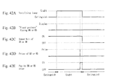
- Figs. 42A to 42E are timing chart diagrams for lighting the notification lamp 25.
- This notification lamp 25 is lighted at a timing shown in Fig. 42A when the fixed pattern for fixing the BB or RB finished the display at a timing shown in Fig. 42B.
- the inner hit flag of the BB or RB is turned ON, as shown in Fig. 42C and when a combination of symbols of the BB or RB is stopped and displayed at the stop of the individual reels 3 to 5 so that the BB or RB prize is caused at the timing shown in Fig. 42D, the notification lamp 25 is extinguished at the timing, as shown in Fig. 42E, to finish the pay-out of coins by the prize.
- the player can recognize that the informing prediction currently displayed is the prediction informing that the inner hit of the BB or RB is caused at the probability of 100 %.
- the game processing determines whether or not the display after stopping all the reels constitutes a predetermined prize combination of symbols with reference to the prize symbol combination table (at Step 110 of Fig. 35). That is, the reel stop control is not carried out entirely by the machine, but the timings of operating the individual stop buttons 16 to 18 by the player matter. Even in case a prize hit flag is erected as a result of the inner lottery, therefore, the prize combination of symbols is not set on the effective prize line, and no prize is awarded, unless the stop buttons 16 to 18 are operated at predetermined timings. This is because the draw control is limited by the four symbols so that the expected combination of prize symbols cannot be achieved in case no prize symbol is present in the four symbols.
- Step 110 When the prize is not awarded, the answer of Step 110 is "NO", and the operation returns to the initial Step 101.
- the processing returns to that of waiting for the operation of the start lever 15 of Step 102 (at Step 111).
- the hopper drive circuit 41 is controlled by the CPU 31, and a predetermined number of coins are paid out to the coin tray 20 by the hopper 38(at Step 112 of Fig. 36).
- Step 113 it is determined (at Step 113) whether or not the BB game is caused.
- this BB game it is carried out (at Step 114).
- Step 115 it is then determined (at Step 115) whether or not the RB game is caused.
- the RB game it is carried out (at Step 116). After this, the operations thus far described are repeated to carry out the game of the slot machine.
- the prize mode determined by the inner lottery is informed to the player through a series of flow of the slot machine game.
- the player is informed of the prize mode by the combination of the kinds of the game starting sounds which are generated by the sound emitting means when the rotation of the individual reels 3 to 5 is stated, the kinds of the display modes (or the reel lamp extinguishing patterns) of the individual back lamps 57a to 57c which are successively staged by the connection staging means in connection with the stop of the individual reels 3 to 5, and the kinds of the display modes (or the reel lamp flashing patterns)of the individual back lamps 57a to 57c which are staged by the stop staging means when all the individual reels 3 to 5 are stopped.
- the player listens to -the game starting sound 1 at the time of operating the start lever 15 , recognizes that the individual back lamps 57a to 57c are extinguished, extinguished and extinguished in this order by the visual sense in the midst of the operation to stop the first reel 3, the second reel 4 and the third reel 5, and recognizes that the individual back lamps 57a to 57c stop the display in the mode of the reel lamp flashing pattern 3 after all the reels 3 to 5 were stopped by the visual sense.
- the prize mode becomes clear as the game advances, as described hereinbefore.
- the rotation of the individual reels 3 to 5 is started by operating the start lever 15 and is successively stopped for each column by operating the individual stop buttons 16 to 18.
- the player is informed of the kinds of the hit flags which are determined by the inner lottery.
- the result of the lottery determined by the random number lottery inside of the machine has not been known at all in respect of the prize mode other than the big hit prize until the patterns are actually stopped and displayed at the individual windows, according to the embodiment, so that the player can predict the prize mode to some degree.
- the player is informed of the fact that the inner hit of the BB or RB is caused by the light display of the notification lamp 25.
- the inner hit of the BB or RB is informed at a probability smaller than 100 %, that is, in the case in which even when the inner hit of the BB or RB is caused by the inner lottery, the inner hit is not necessarily informed, the result of the inner lottery is not notified by the light display of the notification lamp 25.
- the player can feed the pleasure of searching the result of the inner lottery as in searching, for example, the "reach spot".
- the establishment of a flag of a specified prize mode may be notified by using an existing display device.
- the establishment of a specified flag may be notified by emitting a special sound from the speaker 39.
- the establishment of a specified flag may be notified by vibrating the individual reels 3 to 5.
- the notification means may be realized by information means for informing the prediction of establishment of flags of the individual prize modes.
- the establishment of a specified flag may be notified by displaying a mode of flashing the individual back lamps 57a to 57c of the individual reels 3 to 5 by a specified information mode after the end of the reel lamp flashing display which is effected by the stop staging means at the stop time of the individual reels.
- the liquid crystal display unit 24 may be used as the information means for informing the prediction of establishing flags of the individual prize modes and may also be used as the notification means. That is, instead of informing a prediction by a staging combination of a display mode of the reel back lamps or the like, the prediction may be informed by making a character or the like enter the liquid crystal display unit 24 and by combining changes in the display of the character, or the prediction may be informed by combining the changes in the display of a background image. Furthermore, the notification by the notification means may be carried out by displaying the liquid crystal display unit 24 in a specified mode different from that of informing the prediction.
- the invention should not be limited thereto but can be applied, for example, to a pinball game machine such as a pachinko machine or amusement machines having variable display devices.
- Some game machine is not provided with buttons for stopping the variable display so that the individual variable display portions are successively stopped automatically for each variable display column. In this case, too, effects similar to those of the foregoing embodiments can be achieved if the prize mode informing means is operated at the timing in which the individual variable display columns are automatically stopped.
- the flow of the game such as the operation of the start lever, sampling of a random number for determining a prize mode and starting to rotate the reels in the slot machine of the foregoing embodiment, is replaced by the flow of the game such as the insertion of pachinko balls into a specific prize slot, sampling of a random number for determining a prize mode and starting to rotate the slot machine reels integrated into the pachinko machine.
- the operation of paying out coins which is carried out when the patterns of the reels are stopped and displayed to constitute a specific mode in the slot machines of the foregoing individual embodiments, is replaced by rewarding a special prize in the pachinko game as in providing a large number of balls to the player by opening a variable prize device of an attacker or tulip in the pachinko machine.
Landscapes
- Physics & Mathematics (AREA)
- General Physics & Mathematics (AREA)
- Slot Machines And Peripheral Devices (AREA)
- Pinball Game Machines (AREA)
- Display Devices Of Pinball Game Machines (AREA)
Applications Claiming Priority (4)
| Application Number | Priority Date | Filing Date | Title |
|---|---|---|---|
| JP17217798 | 1998-06-04 | ||
| JP17217798 | 1998-06-04 | ||
| JP18685598 | 1998-06-17 | ||
| JP18685598A JP4487152B2 (ja) | 1998-06-04 | 1998-06-17 | 遊技機 |
Publications (2)
| Publication Number | Publication Date |
|---|---|
| EP0962901A2 true EP0962901A2 (de) | 1999-12-08 |
| EP0962901A3 EP0962901A3 (de) | 2002-01-09 |
Family
ID=26494625
Family Applications (1)
| Application Number | Title | Priority Date | Filing Date |
|---|---|---|---|
| EP99201793A Ceased EP0962901A3 (de) | 1998-06-04 | 1999-06-04 | Spielautomat mit Sondermodusanzeige |
Country Status (4)
| Country | Link |
|---|---|
| US (1) | US6497617B1 (de) |
| EP (1) | EP0962901A3 (de) |
| JP (1) | JP4487152B2 (de) |
| AU (1) | AU741831B2 (de) |
Families Citing this family (30)
| Publication number | Priority date | Publication date | Assignee | Title |
|---|---|---|---|---|
| JP4498393B2 (ja) * | 1998-06-04 | 2010-07-07 | 株式会社ユニバーサルエンターテインメント | 遊技機 |
| JP4498392B2 (ja) * | 1998-06-04 | 2010-07-07 | 株式会社ユニバーサルエンターテインメント | 遊技機 |
| US7452276B2 (en) * | 2002-02-15 | 2008-11-18 | Wms Gaming Inc. | Simulation of mechanical reels on a gaming machine |
| WO2008005364A2 (en) | 2006-06-30 | 2008-01-10 | Wms Gaming Inc. | Wagering game with simulated mechanical reels |
| US9064372B2 (en) * | 2002-02-15 | 2015-06-23 | Wms Gaming Inc. | Wagering game with simulated mechanical reels having an overlying image display |
| JP2004223003A (ja) * | 2003-01-23 | 2004-08-12 | Abilit Corp | スロットマシン |
| US7722456B2 (en) | 2003-03-04 | 2010-05-25 | Igt | Method and apparatus for associating symbols with a state of a gaming device |
| US20050014548A1 (en) * | 2003-07-15 | 2005-01-20 | Alfred Thomas | Method and apparatus for changing an appearance of mechanical devices displayed on a gaming machine |
| US20050096113A1 (en) * | 2003-10-30 | 2005-05-05 | Varujan Gabuchian | Gaming device and game |
| JP2005211593A (ja) * | 2004-02-02 | 2005-08-11 | Aruze Corp | 遊技機、シミュレーションプログラム |
| US20050181879A1 (en) * | 2004-02-18 | 2005-08-18 | Rothschild Wayne H. | Gaming terminal having secondary display |
| JP2006271728A (ja) * | 2005-03-29 | 2006-10-12 | Aruze Corp | 遊技機 |
| US8216051B2 (en) * | 2005-10-31 | 2012-07-10 | Wms Gaming Inc. | Slot machine with alterable reel symbols |
| US20070178959A1 (en) * | 2006-01-30 | 2007-08-02 | Wms Gaming Inc. | Gaming machine having gameplay sequence designators |
| US8403743B2 (en) | 2006-06-30 | 2013-03-26 | Wms Gaming Inc. | Wagering game with simulated mechanical reels |
| US9659459B2 (en) | 2006-07-20 | 2017-05-23 | Aristocrat Technologies Australia Pty Limited | Game server, gaming system and a gaming method |
| US9460582B2 (en) | 2007-07-11 | 2016-10-04 | Bally Gaming, Inc. | Wagering game having display arrangement formed by an image conduit |
| WO2009059138A1 (en) | 2007-11-01 | 2009-05-07 | Wms Gaming Inc. | Wagering game apparatus and method to provide a trusted gaming environment |
| US8821254B2 (en) * | 2008-03-24 | 2014-09-02 | Universal Entertainment Corporation | Gaming machine having effect corresponding to award to be provided for special game and playing method thereof |
| US8342934B2 (en) * | 2008-05-22 | 2013-01-01 | Universal Entertainment Corporation | Gaming machine allowing selection of stopping order of reels for sustaining player's anticipation, and control method thereof |
| US8371946B2 (en) | 2011-02-15 | 2013-02-12 | Wms Gaming Inc. | Display mounting assemblies and gaming terminals with mounting assemblies for display devices |
| JP2013027445A (ja) * | 2011-07-27 | 2013-02-07 | Sophia Co Ltd | スロットマシン |
| JP2013180169A (ja) | 2012-03-05 | 2013-09-12 | Universal Entertainment Corp | ゲーミングマシン、及び、ゲーミングマシンの制御方法 |
| JP5680585B2 (ja) * | 2012-06-07 | 2015-03-04 | 株式会社ユニバーサルエンターテインメント | 遊技機 |
| JP5952727B2 (ja) * | 2012-12-19 | 2016-07-13 | 株式会社ソフイア | スロットマシン |
| JP5771828B2 (ja) * | 2014-03-03 | 2015-09-02 | 株式会社ユニバーサルエンターテインメント | 遊技機 |
| US10502360B2 (en) | 2015-05-15 | 2019-12-10 | Bally Gaming, Inc. | Gaming systems, electronic gaming machines, and mounting assemblies for electronic display device arrangements |
| JP2016168398A (ja) * | 2016-06-27 | 2016-09-23 | 株式会社ユニバーサルエンターテインメント | 遊技機 |
| JP2017060833A (ja) * | 2016-11-29 | 2017-03-30 | 株式会社ユニバーサルエンターテインメント | 遊技機 |
| GB201714626D0 (en) * | 2017-09-12 | 2017-10-25 | Gamesman Ltd | Illuminated rotatable reels for entertainment machines |
Family Cites Families (23)
| Publication number | Priority date | Publication date | Assignee | Title |
|---|---|---|---|---|
| GB2057738B (en) | 1979-08-30 | 1983-09-28 | Questenco Ltd | Gaming machines |
| GB2117155B (en) | 1982-02-25 | 1985-06-26 | Arthur Edward Thomas | Gaming machine |
| JPS58177679A (ja) * | 1982-04-14 | 1983-10-18 | 株式会社ユニバ−サル | スロットマシン |
| GB8321214D0 (en) | 1983-08-05 | 1983-09-07 | Jpm Automatic Machines Ltd | Coin operated gaming/amusement machines |
| US4624459A (en) | 1985-09-12 | 1986-11-25 | Bally Manufacturing Corporation | Gaming device having random multiple payouts |
| JPS62127086A (ja) | 1985-11-27 | 1987-06-09 | 高砂電器産業株式会社 | スロツトマシン |
| DE3830648C2 (de) | 1988-09-09 | 1994-12-08 | Nsm Ag | Münzbetätigtes Spielgerät |
| JPH0824737B2 (ja) | 1989-04-03 | 1996-03-13 | ユニバーサル販売株式会社 | スロットマシン |
| JP2634465B2 (ja) * | 1989-08-21 | 1997-07-23 | ユニバーサル販売株式会社 | スロットマシン |
| US5803451A (en) | 1992-10-02 | 1998-09-08 | Rlt Acquisition, Inc. | Arcade game having multiple score indicators |
| JP3205199B2 (ja) | 1994-12-27 | 2001-09-04 | アルゼ株式会社 | 遊技機 |
| JP3967391B2 (ja) | 1995-08-17 | 2007-08-29 | アルゼ株式会社 | プッシャーゲーム装置 |
| DE19542625C2 (de) | 1995-08-21 | 1998-02-12 | Nsm Ag | Geldspielgerät |
| JPH09271559A (ja) | 1996-04-05 | 1997-10-21 | Olympia:Kk | スロットマシン |
| JP3818603B2 (ja) | 1996-05-21 | 2006-09-06 | 信越石英株式会社 | 石英ガラスの製造方法 |
| JP3775860B2 (ja) | 1996-07-30 | 2006-05-17 | サミー株式会社 | スロットマシン |
| JP3733401B2 (ja) | 1997-03-06 | 2006-01-11 | 株式会社北電子 | スロットマシンの内部当り報知装置及び内部当り報知方法 |
| JPH119761A (ja) | 1997-04-30 | 1999-01-19 | Aruze Kk | 遊技機 |
| GB2326260A (en) | 1997-06-13 | 1998-12-16 | Eurotek Designs Limited | Pay-out selection for game playing apparatus |
| JP3995350B2 (ja) * | 1997-11-19 | 2007-10-24 | アルゼ株式会社 | 遊技機 |
| EP0921504A3 (de) | 1997-12-05 | 2000-12-27 | Aruze Corporation | Spielautomat mit Angabe von Preismodus |
| JPH11226175A (ja) * | 1998-02-17 | 1999-08-24 | Aruze Corp | 遊技機 |
| JPH11244456A (ja) * | 1998-02-27 | 1999-09-14 | Aruze Corp | 遊技機 |
-
1998
- 1998-06-17 JP JP18685598A patent/JP4487152B2/ja not_active Expired - Fee Related
-
1999
- 1999-06-01 AU AU32363/99A patent/AU741831B2/en not_active Ceased
- 1999-06-04 EP EP99201793A patent/EP0962901A3/de not_active Ceased
- 1999-06-04 US US09/325,540 patent/US6497617B1/en not_active Expired - Lifetime
Also Published As
| Publication number | Publication date |
|---|---|
| US6497617B1 (en) | 2002-12-24 |
| JP4487152B2 (ja) | 2010-06-23 |
| JP2000051433A (ja) | 2000-02-22 |
| EP0962901A3 (de) | 2002-01-09 |
| AU3236399A (en) | 1999-12-16 |
| AU741831B2 (en) | 2001-12-13 |
Similar Documents
| Publication | Publication Date | Title |
|---|---|---|
| AU741831B2 (en) | Game machine notifying formation of a specific prize mode | |
| US6315289B1 (en) | Game machine informing small hit prize | |
| JP3265302B2 (ja) | 遊技機 | |
| AU763202B2 (en) | Game machine informing prize mode information in a series of flow of game | |
| JP4111682B2 (ja) | 遊技機 | |
| JP2001058025A (ja) | 遊技機 | |
| AU752329B2 (en) | Game machine informing prize mode information based on stopping all rotating reels | |
| JP2003305163A (ja) | 遊技機 | |
| JP3062193B2 (ja) | 遊技機 | |
| JP2011016024A (ja) | 遊技機 | |
| JP4498393B2 (ja) | 遊技機 | |
| JP4498392B2 (ja) | 遊技機 | |
| JP2003305162A (ja) | 遊技機 | |
| JP2003305157A (ja) | 遊技機 | |
| JP2002360767A (ja) | 遊技機 | |
| JP2006068542A (ja) | 遊技機 | |
| JP2008119524A (ja) | 遊技機 | |
| JP2000300725A (ja) | 遊技機 |
Legal Events
| Date | Code | Title | Description |
|---|---|---|---|
| PUAI | Public reference made under article 153(3) epc to a published international application that has entered the european phase |
Free format text: ORIGINAL CODE: 0009012 |
|
| AK | Designated contracting states |
Kind code of ref document: A2 Designated state(s): AT BE CH CY DE DK ES FI FR GB GR IE IT LI LU MC NL PT SE Kind code of ref document: A2 Designated state(s): AT CH DE FR GB LI |
|
| AX | Request for extension of the european patent |
Free format text: AL;LT;LV;MK;RO;SI |
|
| PUAL | Search report despatched |
Free format text: ORIGINAL CODE: 0009013 |
|
| AK | Designated contracting states |
Kind code of ref document: A3 Designated state(s): AT BE CH CY DE DK ES FI FR GB GR IE IT LI LU MC NL PT SE |
|
| AX | Request for extension of the european patent |
Free format text: AL;LT;LV;MK;RO;SI |
|
| 17P | Request for examination filed |
Effective date: 20020122 |
|
| AKX | Designation fees paid |
Free format text: AT CH DE FR GB LI |
|
| 17Q | First examination report despatched |
Effective date: 20061218 |
|
| STAA | Information on the status of an ep patent application or granted ep patent |
Free format text: STATUS: THE APPLICATION HAS BEEN REFUSED |
|
| 18R | Application refused |
Effective date: 20100522 |