EP0962708A2 - Backofen mit Strömungsleitmitteln - Google Patents
Backofen mit Strömungsleitmitteln Download PDFInfo
- Publication number
- EP0962708A2 EP0962708A2 EP99110680A EP99110680A EP0962708A2 EP 0962708 A2 EP0962708 A2 EP 0962708A2 EP 99110680 A EP99110680 A EP 99110680A EP 99110680 A EP99110680 A EP 99110680A EP 0962708 A2 EP0962708 A2 EP 0962708A2
- Authority
- EP
- European Patent Office
- Prior art keywords
- door
- opening
- baking oven
- oven
- cooling air
- Prior art date
- Legal status (The legal status is an assumption and is not a legal conclusion. Google has not performed a legal analysis and makes no representation as to the accuracy of the status listed.)
- Granted
Links
Images
Classifications
-
- F—MECHANICAL ENGINEERING; LIGHTING; HEATING; WEAPONS; BLASTING
- F24—HEATING; RANGES; VENTILATING
- F24C—DOMESTIC STOVES OR RANGES ; DETAILS OF DOMESTIC STOVES OR RANGES, OF GENERAL APPLICATION
- F24C15/00—Details
- F24C15/006—Arrangements for circulation of cooling air
Definitions
- the present invention relates to an oven with a baking space with a baking space opening, which can be closed by a door, and with a cooling fan that one Cooling air flow from a discharge opening in the front of the oven above the Presses the baking chamber opening into the open.
- Such an oven is known from the publication DE 37 41 975 A1, the Cooking appliance is also operated with steam. Towards the end of the cooking phase, over a controllable steam outlet in the ceiling area of the oven muffle from the Cooking space steam is discharged to the suction side of a fan and at the same time via a controllable air supply opening from the pressure channel of the blower air to the cooking space fed.
- the steam in the cooking chamber is so far dismantled so that no disturbing steam escapes when the oven door is opened. Especially is prevented that one in this area when opening the door Operator or steam flows into the face. This is particularly disadvantageous the exchange of hot muffle air with cooling air and the associated Reduce the oven temperature before opening the oven door.
- the object of the present invention is in an oven according to the preamble of claim 1 with simple means when opening the door an inflow of Prevent operator from hot air.
- the design is particularly simple and can be optimally adjusted to the respective oven structure it is when the flow guide is movably held on the oven, and when opening the door from a rest position to one that deflects the cooling flow downwards Operating position is adjustable. In terms of assembly technology, it is cheap if that Cooling fan for blowing out the cooling air flow from the oven a blow-out shaft is assigned in which the flow guide is held. Furthermore, through this Measure the flow guide held in the oven without its front Affect appearance. In addition, the function of the air directing means can already installation of the exhaust duct in the oven.
- the oven has a door opening switch, which when opening the door an actuator controls that the flow guide moves into the operating position.
- the flow guide could also be biased into the operating position be, and the movement of the flow guide in the operating position by the Opening the door can be released.
- the air guiding means is immovable in the area the discharge opening arranged. It directs the cooling air flow down and When the door is closed, pushes it into an open front located in the door Air duct. When the door is open, the downward directs out of the blow-out opening flowing cooling air flow away the hot rising vapor flow down.
- the cooling fan advantageously switches up to a higher output whenever if the door is opened when the baking chamber is hot. Safe protection for the operator when the door is opened, this also ensures that the normal fan output, which is sufficient to cool the oven, is not sufficient here would be great.
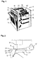
- Fig. 1 an oven 1 is shown according to the state of the art.
- an oven muffle 5 whose The loading opening can be closed at the front by an oven door 7.
- Above the oven door 7 is on the housing 3 a front panel 9 with known Controls 11 and display elements 13 attached.
- a suction fan 15 This sucks Intake openings 17 of the housing 3 and if necessary through a vapor opening 19 in the Ceiling area of the oven muffle 5 cooling air or vapors.
- the suction fan 15 presses the sucked-in air-vapor mixture into one between the suction fan 15 and the front of the oven 1 extending exhaust duct 21.
- Der Blow-out duct 21 has essentially the entire width of the front Oven 1 blow-out openings 23 through which the mixture is transported outdoors (Fig. 1).
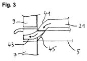
- the oven 1 has above the Muffle 5 on the blow-out shaft 21 in a modified form.
- On one essentially horizontally extending section of the blow-out duct 21 closes a duct arch 41, in which the cooling air flow is guided downwards.
- the duct bend 41 opens out into a likewise curved end extending air duct 43 which is arranged in the oven door 7.
- opening the Door becomes the air duct 43 of the oven door 7 from the area of the duct arch 41 of the blow-out duct 21 is drawn. That is why the blown out streams Cooling air through one arranged in this area over essentially the entire width Air baffle 45 guided, according to the first embodiment ascending vapor flow downwards.
Landscapes
- Engineering & Computer Science (AREA)
- Chemical & Material Sciences (AREA)
- Combustion & Propulsion (AREA)
- Mechanical Engineering (AREA)
- General Engineering & Computer Science (AREA)
- Baking, Grill, Roasting (AREA)
- Electric Ovens (AREA)
Abstract
Description
- Fig. 1
- in einer perspektivischen Darstellung einen Backofen nach dem Stand der Technik;
- Fig. 2
- stark schematisiert in einer Seitenansicht abschnittsweise den Backofen gemäß dem ersten Ausführungsbeispiel und
- Fig. 3
- in einer Darstellung entsprechend Fig. 2 den Backofen gemäß dem zweiten Ausführungsbeispiel.
Claims (6)
- Backofen mit einem Backraum mit einer Backraumöffnung, die durch eine Tür verschließbar ist, und mit einem Kühllüfter, der einen Kühlluftstrom aus einer Ausblasöffnung im Frontbereich des Backofens oberhalb der Backraumöffnung ins Freie drückt, dadurch gekennzeichnet, daß im Bereich der Ausblasöffnung (23) ein Strömungsleitmittel (27; 41) vorgesehen ist, das durch das Öffnen der Tür (7) aktiviert oder freigegeben wird und das den ausgeblasenen Kühlluftstrom im Bereich der Backraumöffnung nach unten leitet.
- Backofen nach Anspruch 1, dadurch gekennzeichnet, daß das Strömungsleitmittel (27) beweglich am Backofen (1) gehaltert ist, und daß es beim Öffnen der Tür (7) von einer Ruhestellung in eine den Kühlluftstrom ablenkende Betriebsstellung verstellbar ist.
- Backofen nach Anspruch 2, dadurch gekennzeichnet, daß dem Kühllüfter (15) zum Ausblasen des Kühlluftstromes aus dem Backofen (1) ein Ausblasschacht (21) zugeordnet ist, und daß in dem Ausblasschacht (21) das Strömungsleitmittel (27) gehaltert ist.
- Backofen nach Anspruch 2 oder 3, dadurch gekennzeichnet, daß der Backofen (1) einen Türöffnungsschalter (31) aufweist, der beim Öffnen der Tür (7) ein Stellglied ansteuert, das das Strömungsleitmittel (27) in die Betriebsstellung bewegt.
- Backofen nach Anspruch 1, dadurch gekennzeichnet, daß das Luftleitmittel (41, 45) unbeweglich im Bereich der Ausblasöffnung angeordnet ist, und daß das Luftleitmittel (41, 45) den Kühlluftstrom nach unten richtet und bei geschlossener Tür (7) den Kühlluftstrom in einen in der Tür (7) angeordneten frontseitig offenen Luftkanal (43) drückt.
- Backofen nach einem der vorhergehenden Ansprüche, dadurch gekennzeichnet, daß der Kühllüfter (15) auf eine höhere Leistung hochschaltet, wenn die Tür (7) bei heißem Backraum (5) geöffnet wird.
Priority Applications (1)
| Application Number | Priority Date | Filing Date | Title |
|---|---|---|---|
| SI9930336T SI0962708T1 (en) | 1998-06-05 | 1999-06-02 | Cooking oven with flow guiding device |
Applications Claiming Priority (2)
| Application Number | Priority Date | Filing Date | Title |
|---|---|---|---|
| DE19825322A DE19825322A1 (de) | 1998-06-05 | 1998-06-05 | Backofen mit Strömungsleitmitteln |
| DE19825322 | 1998-06-05 |
Publications (3)
| Publication Number | Publication Date |
|---|---|
| EP0962708A2 true EP0962708A2 (de) | 1999-12-08 |
| EP0962708A3 EP0962708A3 (de) | 2000-04-26 |
| EP0962708B1 EP0962708B1 (de) | 2003-04-23 |
Family
ID=7870121
Family Applications (1)
| Application Number | Title | Priority Date | Filing Date |
|---|---|---|---|
| EP99110680A Expired - Lifetime EP0962708B1 (de) | 1998-06-05 | 1999-06-02 | Backofen mit Strömungsleitmitteln |
Country Status (4)
| Country | Link |
|---|---|
| EP (1) | EP0962708B1 (de) |
| DE (2) | DE19825322A1 (de) |
| ES (1) | ES2196674T3 (de) |
| SI (1) | SI0962708T1 (de) |
Cited By (3)
| Publication number | Priority date | Publication date | Assignee | Title |
|---|---|---|---|---|
| EP1120607A2 (de) * | 2000-04-20 | 2001-08-01 | WE-MA Werkzeug und Maschinenbau GmbH , Wolfgang Schmidt | Vorrichtung für einen mit einer Ofentür versehenen Erhitzungsofen |
| EP1431670A2 (de) * | 2002-12-18 | 2004-06-23 | BSH Bosch und Siemens Hausgeräte GmbH | Gehäuse für ein Gargerät |
| EP2180259A1 (de) * | 2008-10-27 | 2010-04-28 | UNIELDOM GROUP s. cons. a.r.l. | Nahrungsmittelbackofen mit Vorrichtungen zur Steuerung des Luftstroms |
Families Citing this family (1)
| Publication number | Priority date | Publication date | Assignee | Title |
|---|---|---|---|---|
| DE102007021941A1 (de) | 2007-05-10 | 2008-11-13 | BSH Bosch und Siemens Hausgeräte GmbH | Kochgerät mit einer Dampfausblasung und Verfahren zum Betreiben eines Kochgeräts |
Citations (1)
| Publication number | Priority date | Publication date | Assignee | Title |
|---|---|---|---|---|
| DE3741975A1 (de) | 1987-12-11 | 1989-06-22 | Buderus Kuechentechnik | Vorrichtung zur steuerung eines mit dampf betriebenen gargeraetes und vorrichtung zum betreiben eines solchen geraetes |
Family Cites Families (1)
| Publication number | Priority date | Publication date | Assignee | Title |
|---|---|---|---|---|
| US3889099A (en) * | 1974-07-31 | 1975-06-10 | Gen Electric | Door cooling system |
-
1998
- 1998-06-05 DE DE19825322A patent/DE19825322A1/de not_active Withdrawn
-
1999
- 1999-06-02 ES ES99110680T patent/ES2196674T3/es not_active Expired - Lifetime
- 1999-06-02 EP EP99110680A patent/EP0962708B1/de not_active Expired - Lifetime
- 1999-06-02 DE DE59905135T patent/DE59905135D1/de not_active Expired - Lifetime
- 1999-06-02 SI SI9930336T patent/SI0962708T1/xx unknown
Patent Citations (1)
| Publication number | Priority date | Publication date | Assignee | Title |
|---|---|---|---|---|
| DE3741975A1 (de) | 1987-12-11 | 1989-06-22 | Buderus Kuechentechnik | Vorrichtung zur steuerung eines mit dampf betriebenen gargeraetes und vorrichtung zum betreiben eines solchen geraetes |
Cited By (6)
| Publication number | Priority date | Publication date | Assignee | Title |
|---|---|---|---|---|
| EP1120607A2 (de) * | 2000-04-20 | 2001-08-01 | WE-MA Werkzeug und Maschinenbau GmbH , Wolfgang Schmidt | Vorrichtung für einen mit einer Ofentür versehenen Erhitzungsofen |
| EP1120607A3 (de) * | 2000-04-20 | 2002-05-02 | WE-MA Werkzeug und Maschinenbau GmbH , Wolfgang Schmidt | Vorrichtung für einen mit einer Ofentür versehenen Erhitzungsofen |
| EP1431670A2 (de) * | 2002-12-18 | 2004-06-23 | BSH Bosch und Siemens Hausgeräte GmbH | Gehäuse für ein Gargerät |
| EP1431670A3 (de) * | 2002-12-18 | 2011-02-02 | BSH Bosch und Siemens Hausgeräte GmbH | Gehäuse für ein Gargerät |
| EP2180259A1 (de) * | 2008-10-27 | 2010-04-28 | UNIELDOM GROUP s. cons. a.r.l. | Nahrungsmittelbackofen mit Vorrichtungen zur Steuerung des Luftstroms |
| ITTV20080136A1 (it) * | 2008-10-27 | 2010-04-28 | Unieldom Group S Cons A R L | Forno per la cottura d'alimenti, con dispositivo di controllo a flusso d'aria della dispersione di calore dalla camera di cottura attraverso la luce d'accesso, e sistema integrato di ventilazione per l'isolamento termico con barriera termica della lu |
Also Published As
| Publication number | Publication date |
|---|---|
| ES2196674T3 (es) | 2003-12-16 |
| EP0962708B1 (de) | 2003-04-23 |
| SI0962708T1 (en) | 2003-10-31 |
| EP0962708A3 (de) | 2000-04-26 |
| DE59905135D1 (de) | 2003-05-28 |
| DE19825322A1 (de) | 1999-12-09 |
Similar Documents
| Publication | Publication Date | Title |
|---|---|---|
| EP0752561B1 (de) | Backofen | |
| EP0476364B1 (de) | Backofen | |
| EP0598211B1 (de) | Backofen, insbesondere mit einer Einrichtung für pyrolytische Selbstreinigung | |
| DE3519423C2 (de) | ||
| EP2476960B1 (de) | Umschaltvorrichtung für eine Dunstabzugshaube zum Umschalten zwischen Umluft- und Abluftbetrieb | |
| DE3931482C2 (de) | ||
| EP1979683B1 (de) | Gargerätetür | |
| DE4445594C2 (de) | Back- und Bratofen mit einem Luftkanal | |
| EP0947776B1 (de) | Garofen mit Kühleinrichtung | |
| EP0962708A2 (de) | Backofen mit Strömungsleitmitteln | |
| EP1041346B1 (de) | Backofen mit Kühlluft- und Wrasenkanal | |
| DE19725935A1 (de) | Kombinierte Klimatisier- und Dunsthaube | |
| EP1120607B1 (de) | Vorrichtung für einen mit einer Ofentür versehenen Erhitzungsofen | |
| EP0499803A1 (de) | Backofentür mit Griffleiste | |
| DE10219348B4 (de) | Gargerät | |
| EP2145134A1 (de) | Dunstabzugsvorrichtung | |
| DE2106772A1 (de) | Herd, insbesondere Elektroherd | |
| DE19950817A1 (de) | Dunstabzugsvorrichtung | |
| WO2005001342A1 (de) | Backofen | |
| DE102006023718A1 (de) | Dunstabzugsvorrichtung mit Zulüftung | |
| EP1217308B1 (de) | Dunstabzugshaube | |
| DE4308847A1 (de) | Ofeneinsatz oder Ofen | |
| DE2047224C3 (de) | Backofen, insbesondere Herdbackofen mit einem Abzugkanal | |
| DE4103122A1 (de) | Aufklappbare absaughaube | |
| DE2329024A1 (de) | Herd, insbesondere herd mit pyrolytischer selbstreinigung des bratraumes |
Legal Events
| Date | Code | Title | Description |
|---|---|---|---|
| PUAI | Public reference made under article 153(3) epc to a published international application that has entered the european phase |
Free format text: ORIGINAL CODE: 0009012 |
|
| AK | Designated contracting states |
Kind code of ref document: A2 Designated state(s): DE ES FR GB GR IT SE |
|
| AX | Request for extension of the european patent |
Free format text: AL;LT;LV;MK;RO;SI |
|
| RIN1 | Information on inventor provided before grant (corrected) |
Inventor name: WAGNER, MICHAEL, DR.-ING. Inventor name: STITZL, BERND, DIPL.-ING. Inventor name: SIGMUND, ARMIN, DIPL.-ING. Inventor name: LAPPAT, HANS, DIPL.-ING.(FH) Inventor name: PLANKL, MANFRED, DIPL.-ING. Inventor name: ZIEGLER, FELICITAS, DIPL.-ING. Inventor name: REICHARD, JOACHIM Inventor name: GARCIA, JOSE ANDRES |
|
| PUAL | Search report despatched |
Free format text: ORIGINAL CODE: 0009013 |
|
| AK | Designated contracting states |
Kind code of ref document: A3 Designated state(s): AT BE CH CY DE DK ES FI FR GB GR IE IT LI LU MC NL PT SE |
|
| AX | Request for extension of the european patent |
Free format text: AL;LT;LV;MK;RO;SI |
|
| 17P | Request for examination filed |
Effective date: 20001017 |
|
| AKX | Designation fees paid |
Free format text: DE ES FR GB GR IT SE |
|
| AXX | Extension fees paid |
Free format text: SI PAYMENT 20001017 |
|
| GRAH | Despatch of communication of intention to grant a patent |
Free format text: ORIGINAL CODE: EPIDOS IGRA |
|
| GRAH | Despatch of communication of intention to grant a patent |
Free format text: ORIGINAL CODE: EPIDOS IGRA |
|
| GRAA | (expected) grant |
Free format text: ORIGINAL CODE: 0009210 |
|
| AK | Designated contracting states |
Designated state(s): DE ES FR GB GR IT SE |
|
| AX | Request for extension of the european patent |
Extension state: SI |
|
| REG | Reference to a national code |
Ref country code: GB Ref legal event code: FG4D Free format text: NOT ENGLISH |
|
| REF | Corresponds to: |
Ref document number: 59905135 Country of ref document: DE Date of ref document: 20030528 Kind code of ref document: P |
|
| GBT | Gb: translation of ep patent filed (gb section 77(6)(a)/1977) | ||
| PG25 | Lapsed in a contracting state [announced via postgrant information from national office to epo] |
Ref country code: GR Free format text: LAPSE BECAUSE OF FAILURE TO SUBMIT A TRANSLATION OF THE DESCRIPTION OR TO PAY THE FEE WITHIN THE PRESCRIBED TIME-LIMIT Effective date: 20030723 |
|
| REG | Reference to a national code |
Ref country code: SE Ref legal event code: TRGR |
|
| ET | Fr: translation filed | ||
| REG | Reference to a national code |
Ref country code: ES Ref legal event code: FG2A Ref document number: 2196674 Country of ref document: ES Kind code of ref document: T3 |
|
| RAP2 | Party data changed (patent owner data changed or rights of a patent transferred) |
Owner name: BSH BOSCH UND SIEMENS HAUSGERAETE GMBH |
|
| PLBE | No opposition filed within time limit |
Free format text: ORIGINAL CODE: 0009261 |
|
| STAA | Information on the status of an ep patent application or granted ep patent |
Free format text: STATUS: NO OPPOSITION FILED WITHIN TIME LIMIT |
|
| 26N | No opposition filed |
Effective date: 20040126 |
|
| PGFP | Annual fee paid to national office [announced via postgrant information from national office to epo] |
Ref country code: SE Payment date: 20040623 Year of fee payment: 6 |
|
| REG | Reference to a national code |
Ref country code: SI Ref legal event code: IF |
|
| PG25 | Lapsed in a contracting state [announced via postgrant information from national office to epo] |
Ref country code: IT Free format text: LAPSE BECAUSE OF NON-PAYMENT OF DUE FEES;WARNING: LAPSES OF ITALIAN PATENTS WITH EFFECTIVE DATE BEFORE 2007 MAY HAVE OCCURRED AT ANY TIME BEFORE 2007. THE CORRECT EFFECTIVE DATE MAY BE DIFFERENT FROM THE ONE RECORDED. Effective date: 20050602 |
|
| PG25 | Lapsed in a contracting state [announced via postgrant information from national office to epo] |
Ref country code: SE Free format text: LAPSE BECAUSE OF NON-PAYMENT OF DUE FEES Effective date: 20050603 |
|
| EUG | Se: european patent has lapsed | ||
| REG | Reference to a national code |
Ref country code: SI Ref legal event code: KO00 Effective date: 20060331 |
|
| PGFP | Annual fee paid to national office [announced via postgrant information from national office to epo] |
Ref country code: ES Payment date: 20120628 Year of fee payment: 14 |
|
| PGFP | Annual fee paid to national office [announced via postgrant information from national office to epo] |
Ref country code: DE Payment date: 20130630 Year of fee payment: 15 Ref country code: GB Payment date: 20130620 Year of fee payment: 15 |
|
| PGFP | Annual fee paid to national office [announced via postgrant information from national office to epo] |
Ref country code: FR Payment date: 20130703 Year of fee payment: 15 |
|
| REG | Reference to a national code |
Ref country code: DE Ref legal event code: R119 Ref document number: 59905135 Country of ref document: DE |
|
| GBPC | Gb: european patent ceased through non-payment of renewal fee |
Effective date: 20140602 |
|
| REG | Reference to a national code |
Ref country code: DE Ref legal event code: R119 Ref document number: 59905135 Country of ref document: DE Effective date: 20150101 |
|
| REG | Reference to a national code |
Ref country code: FR Ref legal event code: ST Effective date: 20150227 |
|
| PG25 | Lapsed in a contracting state [announced via postgrant information from national office to epo] |
Ref country code: DE Free format text: LAPSE BECAUSE OF NON-PAYMENT OF DUE FEES Effective date: 20150101 |
|
| PG25 | Lapsed in a contracting state [announced via postgrant information from national office to epo] |
Ref country code: GB Free format text: LAPSE BECAUSE OF NON-PAYMENT OF DUE FEES Effective date: 20140602 Ref country code: FR Free format text: LAPSE BECAUSE OF NON-PAYMENT OF DUE FEES Effective date: 20140630 |
|
| REG | Reference to a national code |
Ref country code: ES Ref legal event code: FD2A Effective date: 20150724 |
|
| PG25 | Lapsed in a contracting state [announced via postgrant information from national office to epo] |
Ref country code: ES Free format text: LAPSE BECAUSE OF NON-PAYMENT OF DUE FEES Effective date: 20140603 |