EP0962379A2 - Verfahren und Vorrichtung zur Bestimmung der Neutralstellung eines Lenksystems - Google Patents
Verfahren und Vorrichtung zur Bestimmung der Neutralstellung eines Lenksystems Download PDFInfo
- Publication number
- EP0962379A2 EP0962379A2 EP99303923A EP99303923A EP0962379A2 EP 0962379 A2 EP0962379 A2 EP 0962379A2 EP 99303923 A EP99303923 A EP 99303923A EP 99303923 A EP99303923 A EP 99303923A EP 0962379 A2 EP0962379 A2 EP 0962379A2
- Authority
- EP
- European Patent Office
- Prior art keywords
- steering
- signal
- threshold
- generating
- center position
- Prior art date
- Legal status (The legal status is an assumption and is not a legal conclusion. Google has not performed a legal analysis and makes no representation as to the accuracy of the status listed.)
- Granted
Links
- 238000000034 method Methods 0.000 title claims abstract description 16
- 238000001914 filtration Methods 0.000 claims description 6
- 239000012530 fluid Substances 0.000 claims 3
- 238000012544 monitoring process Methods 0.000 claims 3
- 238000005086 pumping Methods 0.000 claims 3
- 238000010586 diagram Methods 0.000 description 4
- 230000007704 transition Effects 0.000 description 4
- 238000004364 calculation method Methods 0.000 description 3
- 230000033001 locomotion Effects 0.000 description 2
- 230000004044 response Effects 0.000 description 2
- 238000005070 sampling Methods 0.000 description 2
- 239000000725 suspension Substances 0.000 description 2
- 102100023116 Sodium/nucleoside cotransporter 1 Human genes 0.000 description 1
- 101710123675 Sodium/nucleoside cotransporter 1 Proteins 0.000 description 1
- 230000001133 acceleration Effects 0.000 description 1
- 230000005540 biological transmission Effects 0.000 description 1
- 238000013016 damping Methods 0.000 description 1
- 238000001514 detection method Methods 0.000 description 1
- 230000000694 effects Effects 0.000 description 1
- 238000005259 measurement Methods 0.000 description 1
- 238000012986 modification Methods 0.000 description 1
- 230000004048 modification Effects 0.000 description 1
- 230000002093 peripheral effect Effects 0.000 description 1
- 238000012545 processing Methods 0.000 description 1
- 239000003381 stabilizer Substances 0.000 description 1
- 238000012360 testing method Methods 0.000 description 1
Images


Classifications
-
- B—PERFORMING OPERATIONS; TRANSPORTING
- B62—LAND VEHICLES FOR TRAVELLING OTHERWISE THAN ON RAILS
- B62D—MOTOR VEHICLES; TRAILERS
- B62D15/00—Steering not otherwise provided for
- B62D15/02—Steering position indicators ; Steering position determination; Steering aids
Definitions
- This invention relates to a method and apparatus for determining the center position of a vehicular steering system. This method and apparatus are particularly useful for controlling an electro-hydraulic power assist steering system.
- a method for determining the center position of a vehicular steering system comprises the steps of: establishing a vehicle velocity and generating a vehicle velocity signal; estimating a steering assist force and generating a steering assist force signal; sensing an instantaneous steering system position and generating an instantaneous steering system position signal; filtering the instantaneous steering wheel position signal when both the vehicle velocity signal exceeds a velocity threshold and the steering assist force signal is less than a force threshold so as to determine a new center position of the vehicular steering system; and updating a current center position with the new center position resulting from the filtering.
- an apparatus for determining the center position of a vehicular steering system includes vehicle velocity sensor for establishing a vehicle velocity and generating a vehicle velocity signal.
- a steering sensor is also included for sensing an instantaneous steering system position and generating an instantaneous steering system position signal.
- a force estimator is included for estimating a steering assist force and generating a steering assist force signal.
- a processor operatively connected to the vehicle velocity and steering sensor and force estimator filters the instantaneous steering wheel position signal when both the vehicle velocity signal exceeds a velocity threshold and the steering assist force signal is less than a force threshold. The processor determines a new center position of the vehicular steering system and updates a current center position with the new center position.
- the present invention provides a method and apparatus for determining the center position of the steering system which will rapidly determine the true center position.
- the method and apparatus of the present invention is part of an electro-hydraulic power assist steering system which uses an electric motor 12 to drive a hydraulic pump, which in turn produces the system pressure used to move the steering rack.
- the pump flow is continuously varied, preferably every millisecond, by control of the speed of the electric motor.
- the pump flow is varied in response the instantaneous position of the steering wheel with respect to a calculated center position, also referred to as the absolute steering wheel angle.
- a system according to the present invention could be utilized to control not only a steering system, but also adjustable suspension units, such as dampers, springs or stabilizer bar systems as well as various aspects of vehicle braking systems.
- control module 14 receives inputs from speed sensor 16, steering sensor 18, and motor current, I M , and motor speed, ⁇ M , from the motor speed controller 20. In return, the control module outputs a desired motor speed, calculated using the absolute steering wheel position, to the motor speed controller 20.
- the processor within the control module and its associated peripheral equipment could be structured according to several different architectures. In a preferred embodiment, however, the processor is configured so that a control program is sequentially read for each unit command from a read-only memory (ROM) which stores preset control programs. Unit commands are executed by a central processing unit (CPU).
- the processor integrally includes an input-output control circuit (I/O) for exchanging data with external devices and a random access memory (RAM) for temporarily holding data while the data are being processed.
- I/O input-output control circuit
- RAM random access memory
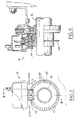
- Steering sensor 18 includes means for measuring the absolute steering position, which represents the angular excursion of the steering wheel from a center position, which is determined by the steering sensor in conjunction with the control module and means.
- steering sensor 18 comprises shutter wheel 28, attached to steering shaft 36, which shaft rotates in unison with the steering wheel as the steering wheel is turned by the driver of the vehicle.
- Shutter wheel 28 has a plurality of apertures 30, in this case 40 in number, which apertures serve to trigger the activity of detectors A and B as the shutter wheel is rotated with the steering system of the vehicle.
- the steering sensor provides a signal 80 times during one revolution of the steering wheel and as a result each of the 80 signals or steps indicates 4.5° of rotation of the steering system.
- a shutter having a greater number of apertures could be used. This considerably increases the resolution and correspondingly the precision of the sensor.
- each of detectors A and B includes a light emitting diode (LED), 32 and a photo diode, 34.
- the combination of the LED and photo diode is used to detect movement of shutter wheel 28 and, hence, the steering system.
- the photo diodes have two states-i.e., they are bistable.
- a conducting state occurs whenever light from the paired LED passes through an aperture 30 in the shutter wheel and impinges upon the photo diode.
- the output of the detector circuit then rises to approximately 5 volts.
- a non-conducting state exists whenever the shutter wheel blocks the transmission of light between the LED and the photo diode.
- clockwise rotation of shutter wheel 28 produces a wave form pattern for the detectors in which detector A undergoes its transition prior to detector B. In other words, detector A leads detector B.
- FIG. 6 is a tabulation of the wave forms shown in FIGS. 5A and 5B in a digital format.
- the approximately 5 volts maximum output of the detectors is treated as a logical "1", while the zero output state is treated as a logical "0".
- FIG. 6 shows each of the possible logic pair states which could be output by detectors A and B. The pairs are arranged in the order in which they will be received by control module 14 for both counterclockwise and clockwise rotation. As seen in FIG. 6, counterclockwise rotation is read from the bottom of the figure to the upper part of the figure with clockwise rotation being read from the top of the tabulation to the lower part of the tabulation.
- detectors A and B are further processed by control module 14 to yield a signal indicating the steering system speed or angular velocity. This operation is performed quite simply by merely tracking the number of transitions of one or both detectors during a given unit of time. The number of such transitions during the sampling period will be directly proportional to the angular speed of the steering system.
- FIG. 2 comprises a logic flow block diagram in accordance with an embodiment of this invention.
- the processor within control module 14 transfers to block 40 and a loop counter, CNT, is initialized at a predetermined value, which in the presently preferred embodiment is 20.
- the processor then transfers to block 42 where two conditions are evaluated to determine if the data being generated by the steering system can be used to rapidly and accurately find the center position of the steering system.
- the first condition is that the vehicle velocity, V s , must exceed a speed threshold, which in the presently preferred embodiment is set at 20mph.
- the second condition involves evaluating an estimate of the steering forces applied to the steering rack and ensuring that the processor only proceeds when the estimated steering assist force is below a predetermined force threshold.
- the present invention provides an estimated steering rack force signal without requiring additional sensors beyond those already required for steering system operation. It has been determined through experimentation that the pump load on the electric motor 12 can be related directly to the forces on the steering rack. Therefore, the present invention evaluates the pump load signal, T p , to determine when it is below a pump load threshold, K P before the processor proceeds to block 44.
- the processor gets the pump motor speed and current from the motor speed controller 20. Once these two conditions are satisfied, the processor proceeds to block 44, where the steering position data is filtered to determine the center position.
- the processor calculates an absolute steering position, ⁇ ABS , which is determined by subtracting a calculated error, ⁇ ERR , from an instantaneous steering position, ⁇ SW , acquired from the steering sensor 18.
- the calculated error, ⁇ ERR represents the difference between the steering position at vehicle start-up and the true steering center position. So, if the vehicle were started with the wheels pointed straight, the calculated error would be zero and the absolute steering position, ⁇ ABS , would equal the instantaneous steering position, ⁇ SW .
- the processor gets a new, or updated, absolute steering position, ⁇ ABS(N) However, before this can be used as a control input parameter, the processor performs a quality analysis at block 46.
- the processor calculates the numerical differential of the calculated error, ⁇ ERR , by dividing the difference of the latest two values of the calculated error, ⁇ ERR , by a value representative of a time step for a single pass through the loop. The result is compared to an error threshold, K ERR .
- Blocks 46, 48,, 50 and 52 require that ⁇ ERR is less than the error threshold for 100 consecutive passes before declaring the absolute steering position, ⁇ ABS , good enough to be used.
- the processor at block 54 switches a quality flag to indicate that a usable center position has been found and that the resultant absolute steering position, ⁇ ABS , can be used for control purposes.
- each time ⁇ ERR is less than the error threshold the processor proceeds from block 46 to block 48 and increments a counter, ErrCNT, and checks, at block 50 whether the counter has reached 100, or any other value established through testing that provides the degree of confidence necessary for a given control system. If the counter has not reached 100, the processor proceeds back to block 42, incrementing CNT at block 56. Referring back to block 46, if ⁇ ERR is greater than the error threshold, the processor proceeds to block 52 where the error counter, ErrCNT, is reset. Again, the processor proceeds back to block 42, incrementing CNT at block 56.
- the processor continues to improve the precision of the absolute steering position until the processor determines at block 58 that the loop counter, CNT, exceeds a loop counter threshold, which in the present invention is set at 300000. When this occurs, the processor proceeds to block 60 and fixes the center position by fixing the calculated error, ⁇ ERR , at the latest value and terminates further execution of the algorithm until the next time the vehicle is started.
Landscapes
- Engineering & Computer Science (AREA)
- Chemical & Material Sciences (AREA)
- Combustion & Propulsion (AREA)
- Transportation (AREA)
- Mechanical Engineering (AREA)
- Steering Control In Accordance With Driving Conditions (AREA)
- Length Measuring Devices With Unspecified Measuring Means (AREA)
Applications Claiming Priority (2)
| Application Number | Priority Date | Filing Date | Title |
|---|---|---|---|
| US88792 | 1998-06-01 | ||
| US09/088,792 US6089344A (en) | 1998-06-01 | 1998-06-01 | Method and apparatus for determining the center position of a steering system |
Publications (3)
| Publication Number | Publication Date |
|---|---|
| EP0962379A2 true EP0962379A2 (de) | 1999-12-08 |
| EP0962379A3 EP0962379A3 (de) | 2002-11-20 |
| EP0962379B1 EP0962379B1 (de) | 2004-12-22 |
Family
ID=22213504
Family Applications (1)
| Application Number | Title | Priority Date | Filing Date |
|---|---|---|---|
| EP99303923A Expired - Lifetime EP0962379B1 (de) | 1998-06-01 | 1999-05-20 | Verfahren und Vorrichtung zur Bestimmung der Neutralstellung eines Lenksystems |
Country Status (4)
| Country | Link |
|---|---|
| US (1) | US6089344A (de) |
| EP (1) | EP0962379B1 (de) |
| JP (1) | JPH11348811A (de) |
| DE (1) | DE69922738T2 (de) |
Families Citing this family (52)
| Publication number | Priority date | Publication date | Assignee | Title |
|---|---|---|---|---|
| JP3673377B2 (ja) * | 1997-09-26 | 2005-07-20 | 光洋精工株式会社 | パワーステアリング装置 |
| US6364050B1 (en) * | 1999-01-15 | 2002-04-02 | Trw Lucas Varity Electric Steering Ltd. | Electrical power assisted steering assemblies |
| JP2001004410A (ja) * | 1999-06-22 | 2001-01-12 | Nisshinbo Ind Inc | ステアリングセンサの故障検知方法 |
| US6834218B2 (en) | 2001-11-05 | 2004-12-21 | Ford Global Technologies, Llc | Roll over stability control for an automotive vehicle |
| US6564897B2 (en) | 2000-02-29 | 2003-05-20 | Crown Equipment Corporation | Synchronized/variable force feedback power steering |
| US6904350B2 (en) | 2000-09-25 | 2005-06-07 | Ford Global Technologies, Llc | System for dynamically determining the wheel grounding and wheel lifting conditions and their applications in roll stability control |
| US7132937B2 (en) * | 2000-09-25 | 2006-11-07 | Ford Global Technologies, Llc | Wheel lift identification for an automotive vehicle using passive and active detection |
| US7109856B2 (en) | 2000-09-25 | 2006-09-19 | Ford Global Technologies, Llc | Wheel lifted and grounded identification for an automotive vehicle |
| US7233236B2 (en) | 2000-09-25 | 2007-06-19 | Ford Global Technologies, Llc | Passive wheel lift identification for an automotive vehicle using operating input torque to wheel |
| US6356188B1 (en) | 2000-09-25 | 2002-03-12 | Ford Global Technologies, Inc. | Wheel lift identification for an automotive vehicle |
| US6683430B2 (en) * | 2000-11-27 | 2004-01-27 | Visteon Global Technologies, Inc. | Method for adjusting an input parameter of an adjustable bolster on a seat |
| US6654674B2 (en) | 2001-11-21 | 2003-11-25 | Ford Global Technologies, Llc | Enhanced system for yaw stability control system to include roll stability control function |
| US6556908B1 (en) | 2002-03-04 | 2003-04-29 | Ford Global Technologies, Inc. | Attitude sensing system for an automotive vehicle relative to the road |
| US7079928B2 (en) | 2002-08-01 | 2006-07-18 | Ford Global Technologies, Llc | System and method for determining a wheel departure angle for a rollover control system with respect to road roll rate and loading misalignment |
| US7194351B2 (en) | 2002-08-01 | 2007-03-20 | Ford Global Technologies, Llc | System and method for determining a wheel departure angle for a rollover control system |
| US7302331B2 (en) | 2002-08-01 | 2007-11-27 | Ford Global Technologies, Inc. | Wheel lift identification for an automotive vehicle |
| US6941205B2 (en) | 2002-08-01 | 2005-09-06 | Ford Global Technologies, Llc. | System and method for deteching roll rate sensor fault |
| US7003389B2 (en) * | 2002-08-01 | 2006-02-21 | Ford Global Technologies, Llc | System and method for characterizing vehicle body to road angle for vehicle roll stability control |
| US7085639B2 (en) | 2002-08-01 | 2006-08-01 | Ford Global Technologies, Llc | System and method for characterizing the road bank for vehicle roll stability control |
| US20040024504A1 (en) * | 2002-08-05 | 2004-02-05 | Salib Albert Chenouda | System and method for operating a rollover control system during an elevated condition |
| US7085642B2 (en) | 2002-08-05 | 2006-08-01 | Ford Global Technologies, Llc | Method and system for correcting sensor offsets |
| US7430468B2 (en) * | 2002-08-05 | 2008-09-30 | Ford Global Technologies, Llc | System and method for sensitizing the activation criteria of a rollover control system |
| US6963797B2 (en) * | 2002-08-05 | 2005-11-08 | Ford Global Technologies, Llc | System and method for determining an amount of control for operating a rollover control system |
| US6961648B2 (en) | 2002-08-05 | 2005-11-01 | Ford Motor Company | System and method for desensitizing the activation criteria of a rollover control system |
| US20040024505A1 (en) | 2002-08-05 | 2004-02-05 | Salib Albert Chenouda | System and method for operating a rollover control system in a transition to a rollover condition |
| US7653471B2 (en) | 2003-02-26 | 2010-01-26 | Ford Global Technologies, Llc | Active driven wheel lift identification for an automotive vehicle |
| US7239949B2 (en) | 2003-02-26 | 2007-07-03 | Ford Global Technologies, Llc | Integrated sensing system |
| US9162656B2 (en) | 2003-02-26 | 2015-10-20 | Ford Global Technologies, Llc | Active driven wheel lift identification for an automotive vehicle |
| US7136731B2 (en) | 2003-06-11 | 2006-11-14 | Ford Global Technologies, Llc | System for determining vehicular relative roll angle during a potential rollover event |
| US7142100B2 (en) * | 2003-10-27 | 2006-11-28 | Ford Global Technologies, Llc | Wheel position indicator |
| US7308350B2 (en) | 2004-05-20 | 2007-12-11 | Ford Global Technologies, Llc | Method and apparatus for determining adaptive brake gain parameters for use in a safety system of an automotive vehicle |
| US7451032B2 (en) | 2004-06-02 | 2008-11-11 | Ford Global Technologies, Llc | System and method for determining desired yaw rate and lateral velocity for use in a vehicle dynamic control system |
| US7640081B2 (en) | 2004-10-01 | 2009-12-29 | Ford Global Technologies, Llc | Roll stability control using four-wheel drive |
| US7668645B2 (en) | 2004-10-15 | 2010-02-23 | Ford Global Technologies | System and method for dynamically determining vehicle loading and vertical loading distance for use in a vehicle dynamic control system |
| US7715965B2 (en) | 2004-10-15 | 2010-05-11 | Ford Global Technologies | System and method for qualitatively determining vehicle loading conditions |
| US7660654B2 (en) | 2004-12-13 | 2010-02-09 | Ford Global Technologies, Llc | System for dynamically determining vehicle rear/trunk loading for use in a vehicle control system |
| US7480547B2 (en) | 2005-04-14 | 2009-01-20 | Ford Global Technologies, Llc | Attitude sensing system for an automotive vehicle relative to the road |
| US7590481B2 (en) | 2005-09-19 | 2009-09-15 | Ford Global Technologies, Llc | Integrated vehicle control system using dynamically determined vehicle conditions |
| US8121758B2 (en) | 2005-11-09 | 2012-02-21 | Ford Global Technologies | System for determining torque and tire forces using integrated sensing system |
| US7600826B2 (en) | 2005-11-09 | 2009-10-13 | Ford Global Technologies, Llc | System for dynamically determining axle loadings of a moving vehicle using integrated sensing system and its application in vehicle dynamics controls |
| US7411366B2 (en) * | 2006-11-13 | 2008-08-12 | Matsushita Electric Industrial Co., Ltd. | Electric power-assist system for manually-operated vehicle |
| MX2008014783A (es) * | 2008-02-05 | 2009-08-27 | Krueger Int Inc | Armazon para silla con soporte hueco ergonomico integral. |
| US9205869B2 (en) | 2010-08-16 | 2015-12-08 | Honda Motor Co., Ltd. | System and method for determining a steering angle for a vehicle and system and method for controlling a vehicle based on same |
| US9073569B2 (en) | 2013-03-19 | 2015-07-07 | Mitsubishi Electric Research Laboratories, Inc. | Determining steering angle of steering column of vehicle |
| US9302702B1 (en) * | 2015-03-27 | 2016-04-05 | Proterra Inc. | Steering control mechanisms for an electric vehicle |
| US10041846B2 (en) | 2015-07-20 | 2018-08-07 | Honda Motor Co., Ltd. | Rotary force diagnostic tools and methods |
| US9964457B2 (en) | 2015-07-20 | 2018-05-08 | Honda Motor Co., Ltd. | Rotary force diagnostic tools and methods |
| US12353210B2 (en) | 2019-07-25 | 2025-07-08 | Ag Leader Technology | Apparatus, systems and methods for automated navigation of agricultural equipment |
| US12583509B1 (en) | 2020-05-18 | 2026-03-24 | Ag Leader Technology | Assisted steering apparatus and associated systems and methods |
| CN113753126B (zh) * | 2020-06-04 | 2022-12-09 | 广州汽车集团股份有限公司 | 汽车转向系统及其方向盘绝对角度诊断方法、汽车及介质 |
| US12403950B2 (en) * | 2021-04-19 | 2025-09-02 | Ag Leader Technology | Automatic steering systems and methods |
| US12509337B2 (en) | 2023-04-13 | 2025-12-30 | Crown Equipment Corporation | Steering shaft assembly for a materials handling vehicle |
Citations (1)
| Publication number | Priority date | Publication date | Assignee | Title |
|---|---|---|---|---|
| US4722545A (en) | 1987-05-04 | 1988-02-02 | Ford Motor Company | Method and apparatus for determining the center position of a vehicular steering system |
Family Cites Families (18)
| Publication number | Priority date | Publication date | Assignee | Title |
|---|---|---|---|---|
| US4621833A (en) * | 1985-12-16 | 1986-11-11 | Ford Motor Company | Control system for multistable suspension unit |
| JPH0665550B2 (ja) * | 1986-01-08 | 1994-08-24 | 株式会社日立製作所 | パワ−ステアリング制御装置 |
| JPH0825468B2 (ja) * | 1987-04-07 | 1996-03-13 | ティーアールダブリュエスエスジエイ株式会社 | パワ−・ステアリング装置用のステアリング・センタ−自動セツト装置 |
| FR2615940B1 (fr) * | 1987-05-27 | 1990-11-30 | Bendix Electronics Sa | Procede et dispositif de determination d'une position de reference d'un mobile |
| US4867466A (en) * | 1987-12-16 | 1989-09-19 | Ford Motor Company | Distance based method and apparatus for determining the center position of a vehicular steering system |
| US4848791A (en) * | 1988-01-06 | 1989-07-18 | Ford Motor Company | Method and apparatus for determining steering position of automotive steering mechanism |
| EP0350819B1 (de) * | 1988-07-11 | 1993-12-29 | Koyo Seiko Co., Ltd. | Einrichtung zur Ermittlung des Mittelpunktes des Lenkungswinkels |
| JPH07100446B2 (ja) * | 1988-09-16 | 1995-11-01 | 日産自動車株式会社 | 車両用中立操舵角検出装置 |
| JP2502745B2 (ja) * | 1989-05-15 | 1996-05-29 | 日産自動車株式会社 | 中立舵角推定装置 |
| JP2507598B2 (ja) * | 1989-05-15 | 1996-06-12 | 日産自動車株式会社 | 中立舵角推定装置 |
| US4999776A (en) * | 1989-11-30 | 1991-03-12 | Ford Motor Company | Method and apparatus for determining the center position of a vehicular steering system |
| EP0440365B1 (de) * | 1990-01-25 | 1995-06-21 | Mitsubishi Jidosha Kogyo Kabushiki Kaisha | Verfahren und Vorrichtung zum Feststellen des Lenkausschlagnullpunktes eines Fahrzeuges |
| US5243188A (en) * | 1991-09-26 | 1993-09-07 | Kabushiki Kaisha Tokai Rika Denki Seisakusho | Neutral position detector for steering wheels having a first and second rotors with aligned slots |
| JPH05162652A (ja) * | 1991-12-10 | 1993-06-29 | Mitsubishi Motors Corp | ステアリングハンドルの中立点推定方法 |
| US5422810A (en) * | 1994-05-05 | 1995-06-06 | Ford Motor Company | Method and apparatus for determining steering position of automotive steering mechanism |
| US5465210A (en) * | 1994-08-18 | 1995-11-07 | General Motors Corporation | Method for determining a vehicle steering wheel center position |
| US5434784A (en) * | 1994-08-26 | 1995-07-18 | General Motors Corporation | Vehicle steering wheel position sensing apparatus |
| US5732372A (en) * | 1995-06-09 | 1998-03-24 | Ford Global Technologies, Inc. | Method for determining a center position of a vehicle steering system |
-
1998
- 1998-06-01 US US09/088,792 patent/US6089344A/en not_active Expired - Lifetime
-
1999
- 1999-05-20 EP EP99303923A patent/EP0962379B1/de not_active Expired - Lifetime
- 1999-05-20 DE DE69922738T patent/DE69922738T2/de not_active Expired - Lifetime
- 1999-05-25 JP JP11145095A patent/JPH11348811A/ja active Pending
Patent Citations (1)
| Publication number | Priority date | Publication date | Assignee | Title |
|---|---|---|---|---|
| US4722545A (en) | 1987-05-04 | 1988-02-02 | Ford Motor Company | Method and apparatus for determining the center position of a vehicular steering system |
Also Published As
| Publication number | Publication date |
|---|---|
| JPH11348811A (ja) | 1999-12-21 |
| EP0962379B1 (de) | 2004-12-22 |
| DE69922738D1 (de) | 2005-01-27 |
| DE69922738T2 (de) | 2005-12-22 |
| EP0962379A3 (de) | 2002-11-20 |
| US6089344A (en) | 2000-07-18 |
Similar Documents
| Publication | Publication Date | Title |
|---|---|---|
| EP0962379B1 (de) | Verfahren und Vorrichtung zur Bestimmung der Neutralstellung eines Lenksystems | |
| US5787375A (en) | Method for determining steering position of automotive steering mechanism | |
| US5790966A (en) | Method for determining steering position of automotive steering mechanism | |
| EP0290225B1 (de) | Verfahren und Gerät zur Ermittlung der Mittelstellung des Lenkungssystems eines Fahrzeugs | |
| US4856607A (en) | Apparatus for automatically setting steering center for use in power steering apparatus | |
| US5742919A (en) | Method and apparatus for dynamically determining a lateral velocity of a motor vehicle | |
| US5422810A (en) | Method and apparatus for determining steering position of automotive steering mechanism | |
| GB2297621A (en) | Method and circuit arrangement for compensating for the signal errors of a sensor | |
| EP2669146B1 (de) | Funktion zur Ermittlung und Abschätzung der Durchschnittlichen Reibung im Lenksystem | |
| KR102918867B1 (ko) | 운전자의 손이 차량의 스티어링 부재를 잡고 있을 확률을 검출하기 위한 방법 및 검출 유닛 | |
| EP0321082B1 (de) | Verfahren und Vorrichtung zur Bestimmung der Mittelstelle eines Fahrzeuglenkungssystems | |
| US6827177B2 (en) | Torque detector and electric power steering controller provided with torque detector | |
| JP2003520362A (ja) | 特に車両用espシステムのためのプロセスを検出する複数のセンサを監視する方法と装置 | |
| EP0323899B1 (de) | Verfahren und Vorrichtung zur Bestimmung der Lenkstellung eines Kraftfahrzeuglenkungssystems | |
| KR102214892B1 (ko) | 운전자에 의한 스티어링 개입을 결정하기 위한 시스템 및 방법 | |
| JPH10258757A (ja) | 操舵制御装置 | |
| US5381336A (en) | Speed averaging for variable effort power steering | |
| US20260116467A1 (en) | Method for Determining Contact with a Steering Handling of a Steering System | |
| JP7660766B2 (ja) | 操舵システムの操舵センサを較正及び/又は初期化するための方法 | |
| US12391310B2 (en) | Steering control device and method | |
| EP4651025A1 (de) | Nullphasenfiltersystem für kraftfahrzeuganwendungen und entsprechendes verfahren | |
| JPH09311036A (ja) | 車両用操舵角検出装置 | |
| JPH08324448A (ja) | 車両用電動式操舵装置の診断装置 | |
| JP2705079B2 (ja) | 車両運動状態推定用パラメータ修正装置 | |
| JPH09127150A (ja) | ヨーレートセンサの異常検出装置 |
Legal Events
| Date | Code | Title | Description |
|---|---|---|---|
| PUAI | Public reference made under article 153(3) epc to a published international application that has entered the european phase |
Free format text: ORIGINAL CODE: 0009012 |
|
| AK | Designated contracting states |
Kind code of ref document: A2 Designated state(s): AT BE CH CY DE DK ES FI FR GB GR IE IT LI LU MC NL PT SE |
|
| AX | Request for extension of the european patent |
Free format text: AL;LT;LV;MK;RO;SI |
|
| PUAL | Search report despatched |
Free format text: ORIGINAL CODE: 0009013 |
|
| AK | Designated contracting states |
Kind code of ref document: A3 Designated state(s): AT BE CH CY DE DK ES FI FR GB GR IE IT LI LU MC NL PT SE |
|
| AX | Request for extension of the european patent |
Free format text: AL;LT;LV;MK;RO;SI |
|
| 17P | Request for examination filed |
Effective date: 20030326 |
|
| AKX | Designation fees paid |
Designated state(s): DE FR GB |
|
| 17Q | First examination report despatched |
Effective date: 20030812 |
|
| GRAP | Despatch of communication of intention to grant a patent |
Free format text: ORIGINAL CODE: EPIDOSNIGR1 |
|
| GRAJ | Information related to disapproval of communication of intention to grant by the applicant or resumption of examination proceedings by the epo deleted |
Free format text: ORIGINAL CODE: EPIDOSDIGR1 |
|
| GRAP | Despatch of communication of intention to grant a patent |
Free format text: ORIGINAL CODE: EPIDOSNIGR1 |
|
| GRAS | Grant fee paid |
Free format text: ORIGINAL CODE: EPIDOSNIGR3 |
|
| GRAA | (expected) grant |
Free format text: ORIGINAL CODE: 0009210 |
|
| AK | Designated contracting states |
Kind code of ref document: B1 Designated state(s): DE FR GB |
|
| REG | Reference to a national code |
Ref country code: GB Ref legal event code: FG4D |
|
| REG | Reference to a national code |
Ref country code: IE Ref legal event code: FG4D |
|
| REF | Corresponds to: |
Ref document number: 69922738 Country of ref document: DE Date of ref document: 20050127 Kind code of ref document: P |
|
| REG | Reference to a national code |
Ref country code: GB Ref legal event code: 732E |
|
| PLBE | No opposition filed within time limit |
Free format text: ORIGINAL CODE: 0009261 |
|
| STAA | Information on the status of an ep patent application or granted ep patent |
Free format text: STATUS: NO OPPOSITION FILED WITHIN TIME LIMIT |
|
| 26N | No opposition filed |
Effective date: 20050923 |
|
| ET | Fr: translation filed | ||
| REG | Reference to a national code |
Ref country code: GB Ref legal event code: 746 Effective date: 20061128 |
|
| PGFP | Annual fee paid to national office [announced via postgrant information from national office to epo] |
Ref country code: GB Payment date: 20090407 Year of fee payment: 11 |
|
| PGFP | Annual fee paid to national office [announced via postgrant information from national office to epo] |
Ref country code: FR Payment date: 20100525 Year of fee payment: 12 |
|
| GBPC | Gb: european patent ceased through non-payment of renewal fee |
Effective date: 20100520 |
|
| PG25 | Lapsed in a contracting state [announced via postgrant information from national office to epo] |
Ref country code: GB Free format text: LAPSE BECAUSE OF NON-PAYMENT OF DUE FEES Effective date: 20100520 |
|
| REG | Reference to a national code |
Ref country code: FR Ref legal event code: ST Effective date: 20120131 |
|
| PG25 | Lapsed in a contracting state [announced via postgrant information from national office to epo] |
Ref country code: FR Free format text: LAPSE BECAUSE OF NON-PAYMENT OF DUE FEES Effective date: 20110531 |
|
| PGFP | Annual fee paid to national office [announced via postgrant information from national office to epo] |
Ref country code: DE Payment date: 20120531 Year of fee payment: 14 |
|
| PG25 | Lapsed in a contracting state [announced via postgrant information from national office to epo] |
Ref country code: DE Free format text: LAPSE BECAUSE OF NON-PAYMENT OF DUE FEES Effective date: 20131203 |
|
| REG | Reference to a national code |
Ref country code: DE Ref legal event code: R119 Ref document number: 69922738 Country of ref document: DE Effective date: 20131203 |