EP0961074A2 - Beleuchtungseinrichtung für Fahrzeuge - Google Patents
Beleuchtungseinrichtung für Fahrzeuge Download PDFInfo
- Publication number
- EP0961074A2 EP0961074A2 EP99110040A EP99110040A EP0961074A2 EP 0961074 A2 EP0961074 A2 EP 0961074A2 EP 99110040 A EP99110040 A EP 99110040A EP 99110040 A EP99110040 A EP 99110040A EP 0961074 A2 EP0961074 A2 EP 0961074A2
- Authority
- EP
- European Patent Office
- Prior art keywords
- cover
- reflector
- lighting device
- cover part
- light source
- Prior art date
- Legal status (The legal status is an assumption and is not a legal conclusion. Google has not performed a legal analysis and makes no representation as to the accuracy of the status listed.)
- Granted
Links
Images


Classifications
-
- B—PERFORMING OPERATIONS; TRANSPORTING
- B60—VEHICLES IN GENERAL
- B60Q—ARRANGEMENT OF SIGNALLING OR LIGHTING DEVICES, THE MOUNTING OR SUPPORTING THEREOF OR CIRCUITS THEREFOR, FOR VEHICLES IN GENERAL
- B60Q1/00—Arrangement of optical signalling or lighting devices, the mounting or supporting thereof or circuits therefor
- B60Q1/0029—Spatial arrangement
- B60Q1/0041—Spatial arrangement of several lamps in relation to each other
-
- F—MECHANICAL ENGINEERING; LIGHTING; HEATING; WEAPONS; BLASTING
- F21—LIGHTING
- F21S—NON-PORTABLE LIGHTING DEVICES; SYSTEMS THEREOF; VEHICLE LIGHTING DEVICES SPECIALLY ADAPTED FOR VEHICLE EXTERIORS
- F21S41/00—Illuminating devices specially adapted for vehicle exteriors, e.g. headlamps
- F21S41/40—Illuminating devices specially adapted for vehicle exteriors, e.g. headlamps characterised by screens, non-reflecting members, light-shielding members or fixed shades
- F21S41/43—Illuminating devices specially adapted for vehicle exteriors, e.g. headlamps characterised by screens, non-reflecting members, light-shielding members or fixed shades characterised by the shape thereof
-
- F—MECHANICAL ENGINEERING; LIGHTING; HEATING; WEAPONS; BLASTING
- F21—LIGHTING
- F21S—NON-PORTABLE LIGHTING DEVICES; SYSTEMS THEREOF; VEHICLE LIGHTING DEVICES SPECIALLY ADAPTED FOR VEHICLE EXTERIORS
- F21S41/00—Illuminating devices specially adapted for vehicle exteriors, e.g. headlamps
- F21S41/40—Illuminating devices specially adapted for vehicle exteriors, e.g. headlamps characterised by screens, non-reflecting members, light-shielding members or fixed shades
- F21S41/47—Attachment thereof
-
- F—MECHANICAL ENGINEERING; LIGHTING; HEATING; WEAPONS; BLASTING
- F21—LIGHTING
- F21S—NON-PORTABLE LIGHTING DEVICES; SYSTEMS THEREOF; VEHICLE LIGHTING DEVICES SPECIALLY ADAPTED FOR VEHICLE EXTERIORS
- F21S43/00—Signalling devices specially adapted for vehicle exteriors, e.g. brake lamps, direction indicator lights or reversing lights
- F21S43/50—Signalling devices specially adapted for vehicle exteriors, e.g. brake lamps, direction indicator lights or reversing lights characterised by aesthetic components not otherwise provided for, e.g. decorative trim, partition walls or covers
Definitions
- the invention relates to a lighting device for vehicles with a Housing, with a translucent that closes the housing End plate, with at least one reflector arranged in the housing, with a light source assigned to the reflector, with one between the light source and cover plate arranged cover and a reflector surrounding frame-like cover part.
- a headlight for motor vehicles serves as the lighting device with two reflectors. Both reflectors are in a pot-shaped housing arranged and together through a translucent lens covered. The outer lens is on with its outer peripheral edge put the outer edge of the pot-shaped housing. Between Reflectors and the lens is a surrounding the reflectors Cover part arranged. The cover is made of plastic and attached to the Cover disc held. With a lens, which at least has optics-free areas, the cover shields the interior of the pot-shaped Housing against views from the outside.
- Both reflectors are one Assigned light source, which are formed by incandescent lamps. The light bulbs are placed in the top of the reflectors Receiving opening inserted. Between the light sources and the Cover plate are arranged hood-like shields.
- the Covering screens can serve as decorative caps and are long Support arm connected to the edge of the receiving opening of the reflectors.
- the object of the invention is that described in the preamble of claim 1
- the frame-like cover part is also the holder for the cover screen.
- the cover part holding the cover screen is either on the outer edge of the housing or the lens can be securely fixed.
- the reflector has no connection geometry for fastening the cover screen is a effective loss of reflective surface avoidable.
- the material of the cover screen must not be adapted to that of the reflector.
- the galvanized shielding part attached to the reflector would have an aluminum surface Reflector lead to contact corrosion.
- the cover screen has a side Support element connected to the upper inside of the frame-like cover part is. As a result, at least a section of the support element is at a glance shielded diagonally from above by the cover part itself.
- this is frame-like cover part together with the cover screen in one piece Component.
- the component is inexpensive to manufacture if it is injection molded is made of plastic.
- the cover screen and the cover part carrying the cover screen are torsionally rigid when the cover is hood-like and that Supporting element is formed like a groove, the hood and the groove for Reflector are open, and if the cover screen with a double wall executed cover part on the inner wall of the frame-like cover part is molded.
- the cover part together with the cover screen is without additional adjustable tool parts made of plastic by injection molding producible.
- the headlamp has a harmonious overall impression when the Cover screen and the frame-like cover part on the lens facing side has the same colored surface.
- the colored surface can be formed by a high-gloss, silver-colored layer.
- a decorative cap that one as Light source serving lamp is associated with a yellow glass bulb.
- the cover shade only serves to cover the yellow lamp.
- a lighting device with a headlight reflector advantageous if the cover a decorative cap for the light source of Headlights and / or a radiation shield held on the reflector for the Headlight is.
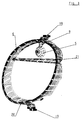
- the headlamp has a pot-shaped housing made of plastic (1), the front opening of which is made of a plastic translucent lens (2) is closed.
- the lens (2) is with its outer peripheral edge in a receiving bed (14) of the outer Edge of the pot-shaped housing (1) used.
- the lens (2) is by means of an adhesive introduced into the receiving bed (14) with the housing (1) tightly connected.
- the portion of the headlamp shown in Figure 1 is circular design and has a reflector (12) in the lower area Low beam and in a top area a reflector (3) for flashing light
- the reflectors are bowl-shaped and run with the adjacent edges at an equidistant distance from each other.
- the Reflectors (3, 12) have a receiving opening (15 or 16).
- a lamp Light source (4) with the socket (17) inserted) while in the receiving opening (16) a lamp serving as a light source (18) is arranged.
- a lamp serving as a light source (18) is arranged inside the The headlight is between the reflectors (3, 12) and the lens (2) a frame-like cover part (6) is arranged.
- the frame-like cover is made of plastic and is with holding tabs (19) on the receiving bed (14) Housing (1) fixed.
- the frame-like cover part (6) has both Reflectors (3.12) surrounding double-walled ring section (20) and one web (21) extending between the two reflectors.
- the lamp serving as the light source (4) has a yellow glass bulb (11)
- a hood-like Cover screen (5) arranged on a channel-shaped support element (9) the upper inner side wall of the double-walled ring portion (20) of the Cover part (6) is integrally formed.
- the facing the end plate (2) Surface (7) of the cover screen (5) and the cover part (6) and Surface (8) of the reflectors (3 and 12) with a high-gloss, silver-colored layer.
- FIG 2 is between the light source (18) for low beam and the End plate (2) a cover screen (5) shown in phantom.
- the Covering screen (5) with its supporting element (9) is on a side surface of the web (21) of the cover part (6) formed.
- a radiation shield (13) is arranged, which directly from the Light source (18) emerging and directed towards the front reflector edge Shields light rays.
- the radiation diaphragm (13) is on support arms at the edge of the Receiving opening (16) attached to the reflector (12).
- the reflector (3) and the Cover (5) assigned to reflector (12) serves as a decorative cap.
- the lighting device for vehicles can also be of a rear light for Motor vehicles be formed.
Landscapes
- Engineering & Computer Science (AREA)
- General Engineering & Computer Science (AREA)
- Mechanical Engineering (AREA)
- Non-Portable Lighting Devices Or Systems Thereof (AREA)
Abstract
Description
- 1
- Gehäuse
- 2
- Abschlußscheibe
- 3
- Reflektor
- 4
- Lichtquelle
- 5
- Abdeckschirm
- 6
- Abdeckteil
- 7
- Oberfläche
- 8
- Oberfläche
- 9
- Tragelement
- 10
- innere Wandung
- 11
- Glaskolben
- 12
- Reflektor
- 13
- Strahlenblende
- 14
- Aufnahmebett
- 15
- Aufnahmeöffnung
- 16
- Aufnahmeöffnung
- 17
- Fassung
- 18
- Lichtquelle
- 19
- Haltefahnen
- 20
- Ringabschnitt
- 21
- Steg
Claims (9)
- Beleuchtungseinrichtung für Fahrzeuge mit einem Gehäuse (1), mit einer das Gehäuse (1) abschließenden lichtdurchlässigen Abschlußscheibe (2), mit mindestens einem im Gehäuse (1) angeordneten Reflektor (3), mit einer dem Reflektor (3) zugeordneten Lichtquelle (4), mit einem zwischen Lichtquelle (4) und Abschlußscheibe (2) angeordneten Abdeckschirm (5) und einem den Reflektor (3) umgebenden rahmenartigen Abdeckteil (6), dadurch gekennzeichnet, daß das rahmenartige Abdeckteil (6) zusätzlich der Halter für den Abdeckschirm (5) ist.
- Beleuchtungseinrichtung nach Anspruch 1, dadurch gekennzeichnet, daß der Abdeckschirm (5) in der Anbaulage des Scheinwerfers mit der oberen Innenseite des rahmenartigen Abdeckteils (6) verbunden ist.
- Beleuchtungseinrichtung nach Anspruch 1 oder 2, dadurch gekennzeichnet, daß der Abdeckschirm (5) über ein seitliches Tragelement (9) mit dem Abdeckteil (6) verbunden ist.
- Beleuchtungseinrichtung nach einem der Ansprüche 1 bis 3, dadurch gekennzeichnet, daß das rahmenartige Abdeckteil (6) zusammen mit dem Abdeckschirm (5) ein einstückiges Bauteil ist.
- Beleuchtungseinrichtung nach Anspruch 3, dadurch gekennzeichnet, daß der Abdeckschirm (5) haubenartig und das Tragelement (9) rinnenartig ausgebildet ist, wobei die Haube und die Rinne zum Reflektor (3) hin geöffnet sind.
- Beleuchtungseinrichtung nach Anspruch 5, dadurch gekennzeichnet, daß der Abdeckschirm (5) bei einem aus Kunststoff bestehenden und doppelwandig ausgeführten Abdeckteil (6) an die innere Wandung (10) des rahmenartigen Abdeckteils (6) angeformt ist.
- Beleuchtungseinrichtung nach einem der Ansprüche 1 bis 6, dadurch gekennzeichnet, daß der Abdeckschirm (5) und das rahmenartige Abdeckteil (6) auf der der Abschlußscheibe (2) zugewandten Seite dieselbe farbige Oberfläche (7) aufweist.
- Beleuchtungseinrichtung nach einem der Ansprüche 1 bis 7, dadurch gekennzeichnet, daß der Abdeckschirm (5) eine Zierkappe für die Lichtquelle (4) einer Blinkleuchte ist, bei der als Lichtquelle (4) eine Lampe mit einem gelben Glaskolben (11) dient.
- Beleuchtungseinrichtung nach einem der Ansprüche 1 bis 8, dadurch gekennzeichnet, daß der Abdeckschirm (5) eine Zierkappe für eine Lichtquelle (4) eines Scheinwerfers und/oder einer am Reflektor (12) gehalterten Strahlenblende (13) für einen Scheinwerfer ist.
Applications Claiming Priority (2)
| Application Number | Priority Date | Filing Date | Title |
|---|---|---|---|
| DE19824053 | 1998-05-29 | ||
| DE19824053A DE19824053A1 (de) | 1998-05-29 | 1998-05-29 | Beleuchtungseinrichtung für Fahrzeuge |
Publications (3)
| Publication Number | Publication Date |
|---|---|
| EP0961074A2 true EP0961074A2 (de) | 1999-12-01 |
| EP0961074A3 EP0961074A3 (de) | 2002-01-30 |
| EP0961074B1 EP0961074B1 (de) | 2007-04-11 |
Family
ID=7869296
Family Applications (1)
| Application Number | Title | Priority Date | Filing Date |
|---|---|---|---|
| EP99110040A Expired - Lifetime EP0961074B1 (de) | 1998-05-29 | 1999-05-21 | Beleuchtungseinrichtung für Fahrzeuge |
Country Status (4)
| Country | Link |
|---|---|
| US (1) | US6267488B1 (de) |
| EP (1) | EP0961074B1 (de) |
| DE (2) | DE19824053A1 (de) |
| ES (1) | ES2285803T3 (de) |
Cited By (10)
| Publication number | Priority date | Publication date | Assignee | Title |
|---|---|---|---|---|
| FR2782777A1 (fr) * | 1998-08-27 | 2000-03-03 | Bosch Gmbh Robert | Installation d'eclairage pour vehicule |
| EP1110814A3 (de) * | 1999-12-22 | 2006-04-05 | Hella KGaA Hueck & Co. | Fahrzeugscheinwerfer |
| EP2045518A1 (de) * | 2007-10-04 | 2009-04-08 | Peugeot Citroën Automobiles Sa | Signalleuchte, die eine zusammengebaute Maske und Blende mit verdeckten Montagebauteilen umfasst |
| EP1908629A3 (de) * | 2006-09-29 | 2009-07-15 | Yamaha Hatsudoki Kabushiki Kaisha | Scheinwerfervorrichtung und Fahrzeug |
| EP1908630A3 (de) * | 2006-09-29 | 2009-07-15 | Yamaha Hatsudoki Kabushiki Kaisha | Scheinwerfervorrichtung und Fahrzeug |
| WO2010007028A1 (de) | 2008-07-16 | 2010-01-21 | Osram Gesellschaft mit beschränkter Haftung | Halterungsrahmen mit mindestens einem optischen element |
| EP2157368A1 (de) * | 2008-08-21 | 2010-02-24 | Peugeot Citroën Automobiles Société Anonyme | Optische Einheit für Fahrzeug, mit einer an dem Leuchtgehäuse aufgehängten Blende |
| FR2941282A1 (fr) * | 2009-01-16 | 2010-07-23 | Peugeot Citroen Automobiles Sa | Masque a cache de lumiere pour un bloc optique de vehicule automobile |
| DE102009032891A1 (de) * | 2009-07-13 | 2011-01-20 | Volkswagen Ag | Beleuchtungsvorrichtung eines Kraftfahrzeugs |
| WO2014125226A1 (fr) * | 2013-02-15 | 2014-08-21 | Peugeot Citroen Automobiles Sa | Écran multifonctions pour un bloc optique multifonctions de véhicule |
Families Citing this family (10)
| Publication number | Priority date | Publication date | Assignee | Title |
|---|---|---|---|---|
| US6375341B1 (en) * | 1999-08-20 | 2002-04-23 | Elco Textron, Inc. | Electro-formed bulb shield and method of making same |
| DE19961858A1 (de) * | 1999-12-22 | 2001-06-28 | Hella Kg Hueck & Co | Fahrzeugscheinwerfer |
| DE10144000B4 (de) | 2001-09-07 | 2007-10-04 | Hella Kgaa Hueck & Co. | Fahrzeugscheinwerfer mit mehreren Beleuchtungseinrichtungen |
| EP1432950A4 (de) * | 2001-10-05 | 2007-05-02 | Elco Textron Inc | Lichtblende |
| FR2840387B1 (fr) * | 2002-05-31 | 2005-01-07 | Valeo Vision | Dispositif d'eclairage et/ou de signalisation pour vehicule comprenant un masque |
| DE102004006078B4 (de) * | 2004-02-07 | 2014-04-30 | Hella Kgaa Hueck & Co. | Abschlussscheibe für Scheinwerfer und Überzugsvorrichtung |
| US7014346B2 (en) * | 2004-03-08 | 2006-03-21 | Valeo Sylvania L.L.C. | Light shield mounting for automotive headlamp |
| DE102004039524B4 (de) | 2004-08-14 | 2018-05-09 | Volkswagen Ag | Scheinwerfer mit einer Strahlenblende für ein Fahrzeug |
| US9133996B2 (en) * | 2012-04-17 | 2015-09-15 | Code 3, Inc. | Emergency vehicle light with illuminated bezel |
| CN105584566B (zh) * | 2014-10-24 | 2021-09-24 | 雅马哈发动机株式会社 | 速克达型车辆 |
Citations (1)
| Publication number | Priority date | Publication date | Assignee | Title |
|---|---|---|---|---|
| EP0646495A1 (de) | 1993-09-30 | 1995-04-05 | Honda Giken Kogyo Kabushiki Kaisha | Scheinwerfervorrichtung für ein Motorfahrzeug |
Family Cites Families (12)
| Publication number | Priority date | Publication date | Assignee | Title |
|---|---|---|---|---|
| US1367964A (en) * | 1916-07-20 | 1921-02-08 | Ellsworth A Hawthorne | Illuminating apparatus |
| FR2219651A6 (de) * | 1972-07-20 | 1974-09-20 | Cibie Projecteurs | |
| JP2544660B2 (ja) * | 1988-12-15 | 1996-10-16 | 株式会社小糸製作所 | 自動車用前照灯装置 |
| FR2664363B1 (fr) * | 1990-07-03 | 1992-12-31 | Valeo Vision | Projecteur a plusieurs fonctions, en particulier pour vehicule automobile, adapte a ameliorer l'eclairement d'elements de signalisation routiere. |
| DE4036031C1 (de) * | 1990-11-13 | 1992-02-27 | Hella Kg Hueck & Co, 4780 Lippstadt, De | |
| DE4124374A1 (de) * | 1991-07-23 | 1993-01-28 | Hella Kg Hueck & Co | Scheinwerfer fuer fahrzeuge |
| JP2610088B2 (ja) * | 1993-03-08 | 1997-05-14 | 株式会社小糸製作所 | 補助ランプ内蔵自動車用ヘッドランプ |
| US5386348A (en) * | 1994-05-09 | 1995-01-31 | General Motors Corporation | Vehicle headlamp with snap fit bulb shield |
| JP3061248B2 (ja) * | 1995-01-20 | 2000-07-10 | 株式会社小糸製作所 | 自動車用ヘッドランプ |
| JP3145930B2 (ja) * | 1996-08-02 | 2001-03-12 | 株式会社小糸製作所 | 車輌用前照灯 |
| JP2965930B2 (ja) * | 1997-03-07 | 1999-10-18 | スタンレー電気株式会社 | 車両用前照灯 |
| US6012830A (en) * | 1998-06-23 | 2000-01-11 | Valeo Sylvania L.L.C. | Light shield for a vehicle headlamp |
-
1998
- 1998-05-29 DE DE19824053A patent/DE19824053A1/de not_active Withdrawn
-
1999
- 1999-05-21 ES ES99110040T patent/ES2285803T3/es not_active Expired - Lifetime
- 1999-05-21 EP EP99110040A patent/EP0961074B1/de not_active Expired - Lifetime
- 1999-05-21 DE DE59914286T patent/DE59914286D1/de not_active Expired - Lifetime
- 1999-05-26 US US09/318,627 patent/US6267488B1/en not_active Expired - Fee Related
Patent Citations (1)
| Publication number | Priority date | Publication date | Assignee | Title |
|---|---|---|---|---|
| EP0646495A1 (de) | 1993-09-30 | 1995-04-05 | Honda Giken Kogyo Kabushiki Kaisha | Scheinwerfervorrichtung für ein Motorfahrzeug |
Cited By (15)
| Publication number | Priority date | Publication date | Assignee | Title |
|---|---|---|---|---|
| FR2782777A1 (fr) * | 1998-08-27 | 2000-03-03 | Bosch Gmbh Robert | Installation d'eclairage pour vehicule |
| EP1110814A3 (de) * | 1999-12-22 | 2006-04-05 | Hella KGaA Hueck & Co. | Fahrzeugscheinwerfer |
| US7815353B2 (en) | 2006-09-29 | 2010-10-19 | Yamaha Hatsudoki Kabushiki Kaisha | Headlight device and vehicle |
| EP1908629A3 (de) * | 2006-09-29 | 2009-07-15 | Yamaha Hatsudoki Kabushiki Kaisha | Scheinwerfervorrichtung und Fahrzeug |
| EP1908630A3 (de) * | 2006-09-29 | 2009-07-15 | Yamaha Hatsudoki Kabushiki Kaisha | Scheinwerfervorrichtung und Fahrzeug |
| EP2045518A1 (de) * | 2007-10-04 | 2009-04-08 | Peugeot Citroën Automobiles Sa | Signalleuchte, die eine zusammengebaute Maske und Blende mit verdeckten Montagebauteilen umfasst |
| FR2921875A1 (fr) * | 2007-10-04 | 2009-04-10 | Peugeot Citroen Automobiles Sa | Feu de signalisation comprenant un masque et un ecran assembles avec dissimulation des moyens d'assemblage utilises. |
| WO2010007028A1 (de) | 2008-07-16 | 2010-01-21 | Osram Gesellschaft mit beschränkter Haftung | Halterungsrahmen mit mindestens einem optischen element |
| US8552627B2 (en) | 2008-07-16 | 2013-10-08 | Osram Gesellschaft Mit Beschrankter Haftung | Retaining frame having at least one optical element |
| FR2935114A1 (fr) * | 2008-08-21 | 2010-02-26 | Peugeot Citroen Automobiles Sa | Bloc avant de vehicule automobile, a ecran suspendu au masque |
| EP2157368A1 (de) * | 2008-08-21 | 2010-02-24 | Peugeot Citroën Automobiles Société Anonyme | Optische Einheit für Fahrzeug, mit einer an dem Leuchtgehäuse aufgehängten Blende |
| FR2941282A1 (fr) * | 2009-01-16 | 2010-07-23 | Peugeot Citroen Automobiles Sa | Masque a cache de lumiere pour un bloc optique de vehicule automobile |
| DE102009032891A1 (de) * | 2009-07-13 | 2011-01-20 | Volkswagen Ag | Beleuchtungsvorrichtung eines Kraftfahrzeugs |
| WO2014125226A1 (fr) * | 2013-02-15 | 2014-08-21 | Peugeot Citroen Automobiles Sa | Écran multifonctions pour un bloc optique multifonctions de véhicule |
| FR3002305A1 (fr) * | 2013-02-15 | 2014-08-22 | Peugeot Citroen Automobiles Sa | Ecran multifonctions pour un bloc optique multifonctions de vehicule |
Also Published As
| Publication number | Publication date |
|---|---|
| US6267488B1 (en) | 2001-07-31 |
| ES2285803T3 (es) | 2007-11-16 |
| EP0961074A3 (de) | 2002-01-30 |
| EP0961074B1 (de) | 2007-04-11 |
| DE59914286D1 (de) | 2007-05-24 |
| DE19824053A1 (de) | 1999-12-02 |
Similar Documents
| Publication | Publication Date | Title |
|---|---|---|
| EP0961074A2 (de) | Beleuchtungseinrichtung für Fahrzeuge | |
| EP0745511B1 (de) | Beleuchtungseinrichtung für Fahrzeuge | |
| DE4127402A1 (de) | Fahrzeugscheinwerfer | |
| EP0212211A2 (de) | Abgeblendeter Fahrzeugscheinwerfer mit einem ellipsoidförmigen Reflektor | |
| EP0955207A2 (de) | Mehrkammerleuchte für Fahrzeuge | |
| DE3540130C1 (de) | Scheinwerfer fuer Kraftfahrzeuge | |
| DE19519655B4 (de) | An einem Frontteil eines Fahrzeugs angeordnete Beleuchtungseinrichtung | |
| DE19507585C2 (de) | Scheinwerfer-Leuchten-Einheit für Fahrzeuge | |
| DE10062735A1 (de) | Beleuchtungseinrichtung, insbesondere Scheinwerfer oder Scheinwerferleuchteneinheit für Kraftfahrzeuge | |
| DE19721596C2 (de) | Leuchte, insbesondere Heckleuchte, für Fahrzeuge, vorzugsweise Kraftfahrzeuge | |
| DE19546271A1 (de) | Scheinwerfer für Fahrzeuge | |
| EP1004473B1 (de) | Lichteinheit für Fahrzeuge | |
| DE4445187A1 (de) | Scheinwerfer für Fahrzeuge | |
| EP0679551A2 (de) | Lichteinheit für Kraftfahrzeuge | |
| DE19825558C2 (de) | Fahrzeugleuchte | |
| DE19838911B4 (de) | Beleuchtungseinrichtung eines Fahrzeugs | |
| DE29809618U1 (de) | Scheinwerfer für Fahrzeuge, insbesondere Zusatzscheinwerfer für Kraftfahrzeuge | |
| EP0262586B1 (de) | Kraftfahrzeugscheinwerfer mit Kunststoffglas, ausgerüstet mit einer dem Glas fest verbundenen Aussenkappe | |
| DE102004011090B4 (de) | Scheinwerfer für Fahrzeuge | |
| EP0745512B1 (de) | Leuchteneinrichtung für Kraftfahrzeuge | |
| DE19535704A1 (de) | Scheinwerfer für Fahrzeuge | |
| DE102004039524B4 (de) | Scheinwerfer mit einer Strahlenblende für ein Fahrzeug | |
| DE19745467A1 (de) | Scheinwerfer für Fahrzeuge | |
| EP0636831A1 (de) | Abschatter eines abgeblendeten Scheinwerfers für Fahrzeuge | |
| DE19843986A1 (de) | Scheinwerfer für Fahrzeuge |
Legal Events
| Date | Code | Title | Description |
|---|---|---|---|
| PUAI | Public reference made under article 153(3) epc to a published international application that has entered the european phase |
Free format text: ORIGINAL CODE: 0009012 |
|
| AK | Designated contracting states |
Kind code of ref document: A2 Designated state(s): AT BE CH CY DE DK ES FI FR GB GR IE IT LI LU MC NL PT SE Kind code of ref document: A2 Designated state(s): DE ES FR GB IT |
|
| AX | Request for extension of the european patent |
Free format text: AL;LT;LV;MK;RO;SI |
|
| PUAL | Search report despatched |
Free format text: ORIGINAL CODE: 0009013 |
|
| AK | Designated contracting states |
Kind code of ref document: A3 Designated state(s): AT BE CH CY DE DK ES FI FR GB GR IE IT LI LU MC NL PT SE |
|
| AX | Request for extension of the european patent |
Free format text: AL;LT;LV;MK;RO;SI |
|
| 17P | Request for examination filed |
Effective date: 20020617 |
|
| AKX | Designation fees paid |
Free format text: DE ES FR GB IT |
|
| RAP1 | Party data changed (applicant data changed or rights of an application transferred) |
Owner name: HELLA KGAA HUECK & CO. |
|
| 17Q | First examination report despatched |
Effective date: 20050606 |
|
| RIC1 | Information provided on ipc code assigned before grant |
Ipc: F21V 1/04 20060101AFI20060213BHEP |
|
| 17Q | First examination report despatched |
Effective date: 20050606 |
|
| GRAP | Despatch of communication of intention to grant a patent |
Free format text: ORIGINAL CODE: EPIDOSNIGR1 |
|
| GRAS | Grant fee paid |
Free format text: ORIGINAL CODE: EPIDOSNIGR3 |
|
| GRAA | (expected) grant |
Free format text: ORIGINAL CODE: 0009210 |
|
| AK | Designated contracting states |
Kind code of ref document: B1 Designated state(s): DE ES FR GB IT |
|
| REG | Reference to a national code |
Ref country code: GB Ref legal event code: FG4D Free format text: NOT ENGLISH |
|
| REF | Corresponds to: |
Ref document number: 59914286 Country of ref document: DE Date of ref document: 20070524 Kind code of ref document: P |
|
| GBT | Gb: translation of ep patent filed (gb section 77(6)(a)/1977) |
Effective date: 20070620 |
|
| ET | Fr: translation filed | ||
| REG | Reference to a national code |
Ref country code: ES Ref legal event code: FG2A Ref document number: 2285803 Country of ref document: ES Kind code of ref document: T3 |
|
| PLBE | No opposition filed within time limit |
Free format text: ORIGINAL CODE: 0009261 |
|
| STAA | Information on the status of an ep patent application or granted ep patent |
Free format text: STATUS: NO OPPOSITION FILED WITHIN TIME LIMIT |
|
| 26N | No opposition filed |
Effective date: 20080114 |
|
| PGFP | Annual fee paid to national office [announced via postgrant information from national office to epo] |
Ref country code: ES Payment date: 20080619 Year of fee payment: 10 |
|
| PGFP | Annual fee paid to national office [announced via postgrant information from national office to epo] |
Ref country code: IT Payment date: 20080529 Year of fee payment: 10 |
|
| PGFP | Annual fee paid to national office [announced via postgrant information from national office to epo] |
Ref country code: GB Payment date: 20100329 Year of fee payment: 12 |
|
| REG | Reference to a national code |
Ref country code: ES Ref legal event code: FD2A Effective date: 20090522 |
|
| PGFP | Annual fee paid to national office [announced via postgrant information from national office to epo] |
Ref country code: FR Payment date: 20100525 Year of fee payment: 12 |
|
| PG25 | Lapsed in a contracting state [announced via postgrant information from national office to epo] |
Ref country code: ES Free format text: LAPSE BECAUSE OF NON-PAYMENT OF DUE FEES Effective date: 20090522 |
|
| PG25 | Lapsed in a contracting state [announced via postgrant information from national office to epo] |
Ref country code: IT Free format text: LAPSE BECAUSE OF NON-PAYMENT OF DUE FEES Effective date: 20090521 |
|
| GBPC | Gb: european patent ceased through non-payment of renewal fee |
Effective date: 20110521 |
|
| REG | Reference to a national code |
Ref country code: FR Ref legal event code: ST Effective date: 20120131 |
|
| PG25 | Lapsed in a contracting state [announced via postgrant information from national office to epo] |
Ref country code: FR Free format text: LAPSE BECAUSE OF NON-PAYMENT OF DUE FEES Effective date: 20110531 |
|
| PG25 | Lapsed in a contracting state [announced via postgrant information from national office to epo] |
Ref country code: GB Free format text: LAPSE BECAUSE OF NON-PAYMENT OF DUE FEES Effective date: 20110521 |
|
| REG | Reference to a national code |
Ref country code: DE Ref legal event code: R084 Ref document number: 59914286 Country of ref document: DE Effective date: 20140702 |
|
| PGFP | Annual fee paid to national office [announced via postgrant information from national office to epo] |
Ref country code: DE Payment date: 20170516 Year of fee payment: 19 |
|
| REG | Reference to a national code |
Ref country code: DE Ref legal event code: R081 Ref document number: 59914286 Country of ref document: DE Owner name: HELLA GMBH & CO. KGAA, DE Free format text: FORMER OWNER: HELLA KGAA HUECK & CO., 59557 LIPPSTADT, DE |
|
| REG | Reference to a national code |
Ref country code: DE Ref legal event code: R119 Ref document number: 59914286 Country of ref document: DE |
|
| PG25 | Lapsed in a contracting state [announced via postgrant information from national office to epo] |
Ref country code: DE Free format text: LAPSE BECAUSE OF NON-PAYMENT OF DUE FEES Effective date: 20181201 |