EP0960467B1 - Hysteresebremse - Google Patents
Hysteresebremse Download PDFInfo
- Publication number
- EP0960467B1 EP0960467B1 EP98908067A EP98908067A EP0960467B1 EP 0960467 B1 EP0960467 B1 EP 0960467B1 EP 98908067 A EP98908067 A EP 98908067A EP 98908067 A EP98908067 A EP 98908067A EP 0960467 B1 EP0960467 B1 EP 0960467B1
- Authority
- EP
- European Patent Office
- Prior art keywords
- ring
- hysteresis
- magnetic
- brake according
- hysteresis brake
- Prior art date
- Legal status (The legal status is an assumption and is not a legal conclusion. Google has not performed a legal analysis and makes no representation as to the accuracy of the status listed.)
- Expired - Lifetime
Links
- XEEYBQQBJWHFJM-UHFFFAOYSA-N Iron Chemical compound [Fe] XEEYBQQBJWHFJM-UHFFFAOYSA-N 0.000 claims description 8
- 239000000696 magnetic material Substances 0.000 claims description 5
- 229910052742 iron Inorganic materials 0.000 claims description 4
- 210000002105 tongue Anatomy 0.000 claims description 3
- 239000000463 material Substances 0.000 description 9
- 230000005284 excitation Effects 0.000 description 4
- 238000004519 manufacturing process Methods 0.000 description 3
- 238000000034 method Methods 0.000 description 3
- 238000012545 processing Methods 0.000 description 3
- 230000006978 adaptation Effects 0.000 description 2
- 238000013459 approach Methods 0.000 description 2
- 238000013461 design Methods 0.000 description 2
- 239000000243 solution Substances 0.000 description 2
- 239000004753 textile Substances 0.000 description 2
- 230000005540 biological transmission Effects 0.000 description 1
- 238000010276 construction Methods 0.000 description 1
- 230000008878 coupling Effects 0.000 description 1
- 238000010168 coupling process Methods 0.000 description 1
- 238000005859 coupling reaction Methods 0.000 description 1
- 238000011161 development Methods 0.000 description 1
- 230000018109 developmental process Effects 0.000 description 1
- 230000000694 effects Effects 0.000 description 1
- 238000007654 immersion Methods 0.000 description 1
- 238000002347 injection Methods 0.000 description 1
- 239000007924 injection Substances 0.000 description 1
- 238000003754 machining Methods 0.000 description 1
- 230000005415 magnetization Effects 0.000 description 1
- 238000003801 milling Methods 0.000 description 1
- 238000004804 winding Methods 0.000 description 1
Images


Classifications
-
- H—ELECTRICITY
- H02—GENERATION; CONVERSION OR DISTRIBUTION OF ELECTRIC POWER
- H02K—DYNAMO-ELECTRIC MACHINES
- H02K49/00—Dynamo-electric clutches; Dynamo-electric brakes
- H02K49/06—Dynamo-electric clutches; Dynamo-electric brakes of the synchronous type
- H02K49/065—Dynamo-electric clutches; Dynamo-electric brakes of the synchronous type hysteresis type
-
- H—ELECTRICITY
- H02—GENERATION; CONVERSION OR DISTRIBUTION OF ELECTRIC POWER
- H02K—DYNAMO-ELECTRIC MACHINES
- H02K2213/00—Specific aspects, not otherwise provided for and not covered by codes H02K2201/00 - H02K2211/00
- H02K2213/09—Machines characterised by the presence of elements which are subject to variation, e.g. adjustable bearings, reconfigurable windings, variable pitch ventilators
Definitions
- the present invention relates to a permanent magnet Hysteresis brake with a roller, a hysteresis ring and a magnetic ring provided with magnetic poles.
- Hysteresis clutches or hysteresis brakes are based on magnetic force in general tightening pole in synchronism or on permanent Ummagnetleiter a permanent magnetic material in the Slip mode, the slip performance converted into heat becomes.
- Hysteresis brakes are particularly suitable for Use as a brake when processing material in a production plant such as B. stranding, twisting, Coil winding etc.
- the system defines the The speed at which the material is withdrawn from the drain , where the drain brake defines the pulling force.
- the material from the stock will be more appropriate Way out on a roller, z. B. by it this wraps around, the roller the braking effect of Hysteresis brake transfers to the material.
- the magnetization in the semi-hard magnetic Permanent magnet material can by existing hysteresis realized various arrangements of the excitation magnets become.
- B. DE-PS 28 21 973 a magnetic Torque clutch, which essentially consists of the Combination of a permanent magnet excited hysteresis clutch with there is a permanent magnet eddy current clutch.
- This known clutch or brake has a driving Coupling body on, on one end a flat Hysteresis ring is arranged.
- Opposite this hysteresis ring are several permanent magnets at an appropriate distance provided in a ring arrangement, the Alternating south-north orientation in the course of the ring.
- the Permanent magnets are on the end face of a magnetizable one Disc arranged. A possibility of adjustability of the torque is in this known arrangement not given.
- JP 01234043 discloses a permanent magnet excitation Hysteresis brake with one hysteresis ring and one on one Carrier part attached magnetic ring, which via an adjustment device axially displaceable relative to the hysteresis ring is.
- the FR-A-2 553 741 shows a hysteresis brake that does not have a torque is adjustable.
- DE-A-4 424 457 there is an electromagnetic hysteresis brake shown, the braking torque by the excitation current the solenoid is affected.
- the object of the present invention is a simplified To create hysteresis brake with non-contact Torque transmission of a speed-independent torque, which is manual in its braking torque in very small Steps can be set in a time-saving manner, which ensures exact reproducibility the setting allows as well as equality setting even with a large number of copies guaranteed.
- the hysteresis brake according to the invention is particularly suitable for use in textile processes such as B. the processing of threads, the braking torque being manual in a range between z. B. 10% and 100% in very small steps, e.g. B. 5% steps is adjustable.
- the segmental, radial, magnetized design of the magnetic ring and the assembly with a Soft iron yoke ring brings the advantage of a higher one Exploitation of the relatively expensive magnetic material.
- the configuration of the adjusting device according to the invention a shift in the hysteresis ring without that Braking torque acts on the setting ring.
- the magnetic ring is - Non-rotatable even when adjusting the setting ring connected to a machine-fixed connection plate.
- a locking device which are solved for each adjustment process must, not required.
- the latching device provided according to the invention enables an exact reproducibility of the setting values, while the connection plate provided for adaptation to a Machine the easiest handling of the adjustment device guaranteed.
- a version of the locking device with resilient Pull with spherical attachments as well as evenly distributed longitudinal grooves is as a plastic injection molded part inexpensive to manufacture.
- connection plate or in the adjusting ring Two cooperating locking cams on the connection plate or in the adjusting ring cause the adjustment device only twist in a certain angle range leaves, and consequently incorrect settings avoided become.
- a roller in which the same parts with the same 9, a roller is designated, those for guiding a thread in a textile processing or to apply a thread tension Wrapping this roller serves.
- the roller 9 is via bearing 11 rotatably arranged on an axis 5 and carries a hysteresis ring 1 which is connected to it in a rotationally fixed manner.
- An arrangement in which the magnetic ring 2 and hysteresis ring 1 are reversed compared to the version shown, at which means that the magnetic ring is connected to the roller in a rotationally fixed manner and the hysteresis ring is fastened to a carrier part 4 is obvious.
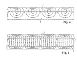
- a closed magnetic ring Permanent magnet material 2 arranged, the outside, d. H. its surface facing the hysteresis ring (Lateral surface), with a variety of circumferentially alternating stamped magnetic poles is provided, as indicated in Fig. 4 is.
- the magnetic ring 2 is radial in segments magnetized and with a soft iron yoke ring 3 connected (Fig. 5).
- the magnetic ring 2 is on the carrier part 4, which is secured against rotation by a hexagonal profile 15, but arranged axially displaceable on the axis 5 is, the carrier part 4 with a threaded approach engages in a threaded spindle 10 of an adjusting ring 7, which is axially fixed but rotatable.
- This Adjustment device does not affect hysteresis 1, but only on the carrier part 4, which carries the magnetic ring 2.
- Fig. 1 is above the Center line shown an end position of the support member which corresponds to the maximum braking torque, and below the Centerline a position where only a smaller one Braking torque is transferable.
- the magnet carrier 4 and the adjusting ring 7 have each part of a locking device, the one hand formed by resilient tongues 6 with a spherical approach which are connected to the adjusting ring 7 and on the other hand formed by evenly distributed longitudinal grooves are formed in the carrier part 4.
- the hysteresis brake is also with a connection plate 8 provided for adaptation to a machine, this Connection plate 8 z. B. has a locking cam 14, which with matching locking cams 16 in the setting ring cooperates so that misadjustments outside the intended Torque range can be avoided (Fig. 3).
- the axial position of the roller 9 is advantageous by a central axial spring 12 against a central one Screw 13 defined.
- this screw is the axial basic setting of the hysteresis brake, d. H. a Fine calibration of any number of copies possible.
- the hysteresis brake is easy to use, finely calibrated and does not transmit any braking torque to the adjusting ring so that a locking device for the adjusting ring is not required.
Landscapes
- Engineering & Computer Science (AREA)
- Power Engineering (AREA)
- Dynamo-Electric Clutches, Dynamo-Electric Brakes (AREA)
Description
- Fig. 1
- einen Schnitt durch eine erfindungsgemäße Hysteresebremse;
- Fig. 2
- eine Stirnansicht auf diese Hysteresebremse;
- Fig. 3
- eine Rückansicht auf diese Hysteresebremse und
- Fig. 4 und 5
- Abwicklungen des Hystereseringes und des Magnetringes.
- 1
- Hysteresering
- 2
- Magnetring
- 3
- Weicheisenrückschlussring
- 4
- Trägerteil
- 5
- Achse
- 6
- Zunge
- 7
- Einstellring
- 8
- Anschlußplatte
- 9
- Laufrolle
- 10
- Gewindespindel
- 11
- Lager
- 12
- Axialfeder
- 13
- Schraube
- 14
- Sperrnocken
- 15
- Sechskantprofil
- 16
- Sperrnocken
Claims (9)
- Dauermagneterregte Hysteresebremse mit einer Laufrolle (9), einem Hysteresering (1) und einem mit Magnetpolen versehenen konzentrisch zu dem Hysteresering (1) angeordneten Magnetring (2), dadurch gekennzeichnet, daß der Magnetring (2) aus Permanentmagnetmaterial segmentweise abwechselnd radial durchmagnetisiert ist, der Hysteresering (1) durch einen einzigen Ringluftspalt vom Magnetring (2) getrennt ist, und der Magnetring (2) an einem Trägerteil (4) befestigt ist, das relativ zum Hysteresering (1) über eine Verstelleinrichtung (4, 10, 7) axial verschiebbar gelagert ist.
- Hysteresebremse nach Anspruch 1, dadurch gekennzeichnet, daß der Hysteresering (1) radial außerhalb des Magnetrings (2) angeordnet ist und der Magnetring (2) das Trägerteil (4) konzentrisch umgibt.
- Hysteresebremse nach einem der Ansprüche 1 bis 2, dadurch gekennzeichnet, daß der Magnetring (2) mit einem Rückschlußring aus Weicheisen (3) verbunden ist.
- Hysteresebremse nach einem der Ansprüche 1 bis 3, dadurch gekennzeichnet, daß die Verstelleinrichtung aus einem Gewindeansatz im Trägerteil (4) und aus einer Gewindespindel (10) in einem Einstellring (7) besteht, der axial feststeht, aber drehbar ist.
- Hysteresebremse nach einem der Ansprüche 1 bis 4, dadurch gekennzeichnet, daß der Magnetring (2) - auch bei einer Verstellung des Einstellrings (7) - drehfest mit der Anschlußplatte (8)verbunden ist.
- Hysteresebremse nach einem der vorhergehenden Ansprüche, dadurch gekennzeichnet, daß zwischen dem Trägerteil (4) für den Magnetring (2) und der Verstelleinrichtung (4, 10, 7) eine Rastanordnung (6) vorgesehen ist.
- Hysteresebremse nach Anspruch 6, dadurch gekennzeichnet, daß die Rastanordnung federnde Zungen (6) mit kugelförmigen Ansatzstücken sowie gleichmässig verteilte Längsrillen aufweist.
- Hysteresebremse nach einem der vorhergehenden Ansprüche, dadurch gekennzeichnet, daß sie mit einer Maschinenanschlußplatte (8) versehen ist, die einen Sperrnocken (14) aufweist, der mit angepaßten Sperrnocken (16) im Einstellring (7) zusammenwirkt.
- Hysteresebremse nach einem der vorhergehenden Ansprüche, dadurch gekennzeichnet, daß sich die Laufrolle (9) über eine Axialfeder (12) auf dem Trägerteil (4) abstützt gegen die Wirkung einer Schraube (13).
Applications Claiming Priority (3)
| Application Number | Priority Date | Filing Date | Title |
|---|---|---|---|
| DE19705290A DE19705290A1 (de) | 1997-02-12 | 1997-02-12 | Hysteresebremse |
| DE19705290 | 1997-02-12 | ||
| PCT/EP1998/000661 WO1998036488A1 (de) | 1997-02-12 | 1998-02-06 | Hysteresebremse |
Publications (2)
| Publication Number | Publication Date |
|---|---|
| EP0960467A1 EP0960467A1 (de) | 1999-12-01 |
| EP0960467B1 true EP0960467B1 (de) | 2003-08-13 |
Family
ID=7819988
Family Applications (1)
| Application Number | Title | Priority Date | Filing Date |
|---|---|---|---|
| EP98908067A Expired - Lifetime EP0960467B1 (de) | 1997-02-12 | 1998-02-06 | Hysteresebremse |
Country Status (6)
| Country | Link |
|---|---|
| US (1) | US6232686B1 (de) |
| EP (1) | EP0960467B1 (de) |
| JP (1) | JP2001512000A (de) |
| DE (2) | DE19705290A1 (de) |
| ES (1) | ES2201449T3 (de) |
| WO (1) | WO1998036488A1 (de) |
Cited By (2)
| Publication number | Priority date | Publication date | Assignee | Title |
|---|---|---|---|---|
| WO2024213205A1 (de) | 2023-04-13 | 2024-10-17 | Schaeffler Technologies AG & Co. KG | Prüfstandsanordnung, prüf- und auswerteeinrichtung sowie verfahren zum abgleich von lagerprüfständen |
| DE102024109694A1 (de) | 2023-04-13 | 2024-10-17 | Schaeffler Technologies AG & Co. KG | Prüf- und Auswerteeinrichtung sowie Verfahren zum Abgleich von Lagerprüfständen |
Families Citing this family (27)
| Publication number | Priority date | Publication date | Assignee | Title |
|---|---|---|---|---|
| DE19856320A1 (de) | 1998-12-07 | 2000-06-08 | Zahnradfabrik Friedrichshafen | Verfahren zum Steuern eines Automatgetriebes |
| DE19934623A1 (de) * | 1999-07-23 | 2001-02-01 | Elero Gmbh | Antriebsvorrichtung aus einem Motor und einem Getriebe |
| DE10313855B4 (de) * | 2003-03-26 | 2015-09-10 | Chr. Mayr Gmbh & Co. Kg | Hysteresekupplung oder -bremse |
| DE10327082B4 (de) * | 2003-06-13 | 2007-06-21 | Vacuumschmelze Gmbh & Co. Kg | Rotationssymmetrischer Hohlkörper aus einer verformbaren dauermagnetischen Legierung sowie dessen Verwendung und Herstellverfahren |
| DE102004057848A1 (de) * | 2004-12-01 | 2006-06-08 | Zf Friedrichshafen Ag | Einstellbare Hysteresekupplung |
| DE102005041973A1 (de) * | 2005-09-03 | 2007-09-13 | Werth, Vladimir, Dipl.-Ing. | Einstellbares-Permanentmagnetkupplung |
| DE102006007924A1 (de) | 2006-02-21 | 2007-08-30 | Saurer Gmbh & Co. Kg | Verfahren zum Einstellen eines Bremsmomentes und Magnethysteresebremse |
| DE102006031310A1 (de) * | 2006-07-06 | 2008-01-24 | Zf Friedrichshafen Ag | Hysteresekupplung |
| DE102006061290A1 (de) * | 2006-12-22 | 2008-06-26 | Oerlikon Textile Gmbh & Co. Kg | Komponente zum Fadentransport an einer Zwirn- oder Kabliermaschine |
| EP1940012A1 (de) * | 2006-12-27 | 2008-07-02 | Valeo Sicherheitssysteme GmbH | Selbsttätigeverstellvorrichtung für eine Kraftfahrzeugtür |
| DE102007059933B3 (de) * | 2007-12-12 | 2009-07-09 | Flück, Anton | Vorrichtung zum Bremsen und Kuppeln mit berührungsloser Kraftübertragung |
| DE102008053166A1 (de) * | 2008-10-24 | 2010-04-29 | Chr. Mayr Gmbh + Co Kg | Abgedichtete Hysteresekupplung oder -bremse |
| US8203316B2 (en) * | 2008-12-18 | 2012-06-19 | Hamilton Sundstrand Corporation | Eddy current torsional damper for generator |
| DE102010009166B4 (de) * | 2010-02-24 | 2016-07-28 | Honigmann Industrielle Elektronik Gmbh | Hystereseeinheit |
| CN103103641A (zh) * | 2012-12-11 | 2013-05-15 | 吴江兰瑞特纺织品有限公司 | 一种磁力绕线轮 |
| CN103103640A (zh) * | 2012-12-11 | 2013-05-15 | 吴江兰瑞特纺织品有限公司 | 一种电磁绕线轮 |
| DE102013101748B4 (de) | 2013-02-21 | 2018-11-29 | Gerd Engel | Rollvorrichtung mit gleichzeitiger Brems- und Feststellfunktion für unterschiedliche Anwendungen |
| CN103397417B (zh) * | 2013-07-27 | 2016-06-01 | 陕西华燕航空仪表有限公司 | 纱线张力恒定装置 |
| WO2015019910A1 (ja) * | 2013-08-07 | 2015-02-12 | 小倉クラッチ株式会社 | スピンドルユニット |
| CN103523591B (zh) * | 2013-10-18 | 2016-04-06 | 陕西华燕航空仪表有限公司 | 大锥度筒纱成型装置 |
| WO2015070854A1 (de) * | 2013-11-13 | 2015-05-21 | Schaeffler Technologies AG & Co. KG | Betätigungseinrichtung für eine kupplungseinrichtung |
| CN105329709B (zh) * | 2015-11-28 | 2018-12-04 | 江阴市华方新技术科研有限公司 | 一种张力储纱器 |
| DE102017128214A1 (de) | 2017-11-29 | 2019-05-29 | Brose Fahrzeugteile Gmbh & Co. Kommanditgesellschaft, Bamberg | Kraftfahrzeugkomponente |
| US10959365B2 (en) * | 2018-08-14 | 2021-03-30 | Cnh Industrial America Llc | System and method for controlling the position of an agricultural implement by applying a braking force to a wheel of the implement |
| JP7185583B2 (ja) * | 2019-04-03 | 2022-12-07 | 小倉クラッチ株式会社 | スピンドルユニット |
| EP3741476B1 (de) * | 2019-05-20 | 2022-12-28 | Schleuniger AG | Richtvorrichtung zum begradigen einer leitung, verfahren zum bremsen von zumindest einer drehbaren rolle in einer richtvorrichtung, kabelverarbeitungsmaschine mit einer richtvorrichtung sowie upgrade-kit für eine kabelverarbeitungsmaschine |
| FI129445B (en) * | 2021-02-11 | 2022-02-28 | Valmet Technologies Oy | Braking of an unpowered roller in a fiber web machine, especially in a roller cutting machine |
Family Cites Families (17)
| Publication number | Priority date | Publication date | Assignee | Title |
|---|---|---|---|---|
| DE1082512B (de) | 1956-09-04 | 1960-05-25 | Philips Nv | Mehrpolige dauermagnetische Wirbelstrombremse fuer Fahrzeuge, insbesondere Kraftfahrzeuge |
| US3068372A (en) * | 1958-11-19 | 1962-12-11 | Havilland Engine Co Ltd | Eddy-current braking apparatus |
| DE1114917B (de) * | 1959-06-04 | 1961-10-12 | Licentia Gmbh | Magnetkupplung |
| US3700941A (en) * | 1971-02-03 | 1972-10-24 | John E Duncan | Adjustable hysteresis clutch and brake |
| JPS53146057A (en) | 1977-05-20 | 1978-12-19 | Vibrac Corp | Magnetic torque coupling |
| US4152617A (en) * | 1977-11-22 | 1979-05-01 | Dana Corporation | Selectively variable torque magnetic brake |
| US4239092A (en) * | 1978-08-28 | 1980-12-16 | Dana Corporation | Adjustable tensioner |
| DE3210167A1 (de) * | 1982-03-19 | 1983-09-29 | Franz Klaus Union Armaturen, Pumpen Gmbh & Co, 4630 Bochum | Vorrichtung zur drehmomentbegrenzung |
| DE3323298A1 (de) * | 1982-06-30 | 1984-01-12 | Mitsubishi Denki K.K., Tokyo | Induktionsmotor mit geringer traegheit und variabler drehzahl |
| FR2553741B1 (fr) | 1983-10-25 | 1988-08-26 | Artus | Rouleau pour l'ensemble a rouleau d'entrainement auto-elevateur, et ensemble equipe d'un tel rouleau |
| DE3732766A1 (de) * | 1986-10-10 | 1988-04-14 | Zahnradfabrik Friedrichshafen | Dauermagneterregte hysteresekupplung bzw. -bremse |
| JP2709821B2 (ja) * | 1988-03-14 | 1998-02-04 | 住友金属工業株式会社 | 渦電流式減速装置 |
| DE8810471U1 (de) * | 1988-08-18 | 1988-10-20 | Fluid Misch- und Dispergiertechnik GmbH, 7860 Schopfheim | Wirbelstromkupplung |
| US5096024A (en) * | 1990-08-10 | 1992-03-17 | Wu Hung Chi | Adjustable magnetic brake |
| US5238095A (en) * | 1992-06-30 | 1993-08-24 | Pedu Jeffrey C | Hysteresis brakes and clutches |
| DE4424457A1 (de) | 1994-07-12 | 1996-01-18 | Zahnradfabrik Friedrichshafen | Elektromagnetische Hysteresebremse |
| US5982063A (en) * | 1997-12-18 | 1999-11-09 | Unique Mobility, Inc. | Electric motor with internal brake |
-
1997
- 1997-02-12 DE DE19705290A patent/DE19705290A1/de not_active Withdrawn
-
1998
- 1998-02-06 EP EP98908067A patent/EP0960467B1/de not_active Expired - Lifetime
- 1998-02-06 ES ES98908067T patent/ES2201449T3/es not_active Expired - Lifetime
- 1998-02-06 WO PCT/EP1998/000661 patent/WO1998036488A1/de not_active Ceased
- 1998-02-06 US US09/355,575 patent/US6232686B1/en not_active Expired - Lifetime
- 1998-02-06 DE DE59809278T patent/DE59809278D1/de not_active Expired - Lifetime
- 1998-02-06 JP JP53530998A patent/JP2001512000A/ja active Pending
Cited By (2)
| Publication number | Priority date | Publication date | Assignee | Title |
|---|---|---|---|---|
| WO2024213205A1 (de) | 2023-04-13 | 2024-10-17 | Schaeffler Technologies AG & Co. KG | Prüfstandsanordnung, prüf- und auswerteeinrichtung sowie verfahren zum abgleich von lagerprüfständen |
| DE102024109694A1 (de) | 2023-04-13 | 2024-10-17 | Schaeffler Technologies AG & Co. KG | Prüf- und Auswerteeinrichtung sowie Verfahren zum Abgleich von Lagerprüfständen |
Also Published As
| Publication number | Publication date |
|---|---|
| JP2001512000A (ja) | 2001-08-14 |
| US6232686B1 (en) | 2001-05-15 |
| DE59809278D1 (de) | 2003-09-18 |
| EP0960467A1 (de) | 1999-12-01 |
| WO1998036488A1 (de) | 1998-08-20 |
| ES2201449T3 (es) | 2004-03-16 |
| DE19705290A1 (de) | 1998-09-24 |
Similar Documents
| Publication | Publication Date | Title |
|---|---|---|
| EP0960467B1 (de) | Hysteresebremse | |
| DE2410702C2 (de) | Elektromagnetisch betätigbare Schlingfederkupplung | |
| DE19733169B4 (de) | Elektromagnetisch gelüftete Reibungs-Sicherheitsbremse mit zwei unabhängigen Bremskreisen | |
| EP1848898B1 (de) | Elektromagnetische bremse mit einem permanentmagneten | |
| DE2312486C2 (de) | Elektromagnetisch betätigbare Schlingfederkupplung | |
| EP0771303B1 (de) | Elektromagnetische hysteresebremse | |
| EP0374268B1 (de) | Selbsttätige Nachstellvorrichtung für elektromagnetisch betätigte Kupplungs- und/oder Bremsaggregate | |
| DE2722366A1 (de) | Elektromagnetische kupplungs- und bremsvorrichtung | |
| DE2821973A1 (de) | Magnetische drehmomentkupplung | |
| DE2627161A1 (de) | Selbsteinstellende elektromagnetkupplung | |
| EP0531752B1 (de) | Rotierend angetriebene Bremstelleranordnung eines Fadenspanners | |
| CH444607A (de) | Verfahren und Vorrichtung zum Aufwickeln von Wickelgut, insbesondere eines Bandes oder Fadens | |
| DE8435225U1 (de) | Elektromagnetische Kupplung | |
| EP0847369A1 (de) | Fadenbremse | |
| DE3727534C2 (de) | ||
| DE102006031310A1 (de) | Hysteresekupplung | |
| DE2419446C2 (de) | Elektromagnetisch betätigbare Kupplung für Textilmaschinen | |
| DE4118778C2 (de) | Staurollenbahn zum Transport von Fördergut | |
| DE4236428A1 (en) | Magnetically actuated torque limiting coupling - has driving cylinder between cylinders with inner and outer rings of magnets permitting relative rotation for torque adjustment | |
| DE2037817B2 (de) | Elektrische induktions-heizvorrichtung | |
| EP0078944A1 (de) | Elektromagnetisch betätigte Federdruckbremse | |
| DE3910046C2 (de) | ||
| EP1142086B1 (de) | Elektromagnetische hystereseeinheit | |
| DE2601121A1 (de) | Elektromagnetisch betaetigte bremse oder kupplung und reibelement dafuer | |
| DE3301760A1 (de) | Als stellmagnet ausgebildeter hubmagnet |
Legal Events
| Date | Code | Title | Description |
|---|---|---|---|
| PUAI | Public reference made under article 153(3) epc to a published international application that has entered the european phase |
Free format text: ORIGINAL CODE: 0009012 |
|
| 17P | Request for examination filed |
Effective date: 19990616 |
|
| AK | Designated contracting states |
Kind code of ref document: A1 Designated state(s): CH DE ES FR GB IT LI |
|
| 17Q | First examination report despatched |
Effective date: 20010123 |
|
| GRAH | Despatch of communication of intention to grant a patent |
Free format text: ORIGINAL CODE: EPIDOS IGRA |
|
| GRAH | Despatch of communication of intention to grant a patent |
Free format text: ORIGINAL CODE: EPIDOS IGRA |
|
| GRAA | (expected) grant |
Free format text: ORIGINAL CODE: 0009210 |
|
| AK | Designated contracting states |
Designated state(s): CH DE ES FR GB IT LI |
|
| REG | Reference to a national code |
Ref country code: GB Ref legal event code: FG4D Free format text: NOT ENGLISH |
|
| REG | Reference to a national code |
Ref country code: CH Ref legal event code: EP |
|
| REG | Reference to a national code |
Ref country code: CH Ref legal event code: NV Representative=s name: DR. LUSUARDI AG |
|
| GBT | Gb: translation of ep patent filed (gb section 77(6)(a)/1977) | ||
| REF | Corresponds to: |
Ref document number: 59809278 Country of ref document: DE Date of ref document: 20030918 Kind code of ref document: P |
|
| REG | Reference to a national code |
Ref country code: ES Ref legal event code: FG2A Ref document number: 2201449 Country of ref document: ES Kind code of ref document: T3 |
|
| ET | Fr: translation filed | ||
| PLBE | No opposition filed within time limit |
Free format text: ORIGINAL CODE: 0009261 |
|
| STAA | Information on the status of an ep patent application or granted ep patent |
Free format text: STATUS: NO OPPOSITION FILED WITHIN TIME LIMIT |
|
| 26N | No opposition filed |
Effective date: 20040514 |
|
| REG | Reference to a national code |
Ref country code: CH Ref legal event code: PFA Owner name: ZF FRIEDRICHSHAFEN AKTIENGESELLSCHAFT Free format text: ZF FRIEDRICHSHAFEN AKTIENGESELLSCHAFT# #88038 FRIEDRICHSHAFEN (DE) -TRANSFER TO- ZF FRIEDRICHSHAFEN AKTIENGESELLSCHAFT# #88038 FRIEDRICHSHAFEN (DE) |
|
| PGFP | Annual fee paid to national office [announced via postgrant information from national office to epo] |
Ref country code: IT Payment date: 20120216 Year of fee payment: 15 |
|
| PGFP | Annual fee paid to national office [announced via postgrant information from national office to epo] |
Ref country code: ES Payment date: 20120307 Year of fee payment: 15 |
|
| PG25 | Lapsed in a contracting state [announced via postgrant information from national office to epo] |
Ref country code: IT Free format text: LAPSE BECAUSE OF NON-PAYMENT OF DUE FEES Effective date: 20130206 |
|
| REG | Reference to a national code |
Ref country code: ES Ref legal event code: FD2A Effective date: 20140408 |
|
| PGFP | Annual fee paid to national office [announced via postgrant information from national office to epo] |
Ref country code: GB Payment date: 20140206 Year of fee payment: 17 |
|
| PG25 | Lapsed in a contracting state [announced via postgrant information from national office to epo] |
Ref country code: ES Free format text: LAPSE BECAUSE OF NON-PAYMENT OF DUE FEES Effective date: 20130207 |
|
| GBPC | Gb: european patent ceased through non-payment of renewal fee |
Effective date: 20150206 |
|
| REG | Reference to a national code |
Ref country code: FR Ref legal event code: PLFP Year of fee payment: 19 |
|
| PG25 | Lapsed in a contracting state [announced via postgrant information from national office to epo] |
Ref country code: GB Free format text: LAPSE BECAUSE OF NON-PAYMENT OF DUE FEES Effective date: 20150206 |
|
| REG | Reference to a national code |
Ref country code: FR Ref legal event code: PLFP Year of fee payment: 20 |
|
| PGFP | Annual fee paid to national office [announced via postgrant information from national office to epo] |
Ref country code: FR Payment date: 20170112 Year of fee payment: 20 Ref country code: CH Payment date: 20170214 Year of fee payment: 20 Ref country code: DE Payment date: 20170131 Year of fee payment: 20 |
|
| REG | Reference to a national code |
Ref country code: DE Ref legal event code: R071 Ref document number: 59809278 Country of ref document: DE |
|
| REG | Reference to a national code |
Ref country code: CH Ref legal event code: PL |