EP0959463B1 - Optisches abtastgerät - Google Patents
Optisches abtastgerät Download PDFInfo
- Publication number
- EP0959463B1 EP0959463B1 EP98901528A EP98901528A EP0959463B1 EP 0959463 B1 EP0959463 B1 EP 0959463B1 EP 98901528 A EP98901528 A EP 98901528A EP 98901528 A EP98901528 A EP 98901528A EP 0959463 B1 EP0959463 B1 EP 0959463B1
- Authority
- EP
- European Patent Office
- Prior art keywords
- light receiving
- sub
- receiving sections
- light
- signal
- Prior art date
- Legal status (The legal status is an assumption and is not a legal conclusion. Google has not performed a legal analysis and makes no representation as to the accuracy of the status listed.)
- Expired - Lifetime
Links
- 230000003287 optical effect Effects 0.000 title claims abstract description 167
- 238000001514 detection method Methods 0.000 description 15
- 238000006073 displacement reaction Methods 0.000 description 15
- 239000004065 semiconductor Substances 0.000 description 10
- 239000000758 substrate Substances 0.000 description 7
- 230000004075 alteration Effects 0.000 description 5
- 230000007423 decrease Effects 0.000 description 4
- 238000004519 manufacturing process Methods 0.000 description 4
- 238000013459 approach Methods 0.000 description 3
- 230000003247 decreasing effect Effects 0.000 description 3
- 238000000034 method Methods 0.000 description 3
- 230000000903 blocking effect Effects 0.000 description 2
- 239000006059 cover glass Substances 0.000 description 2
- 238000009792 diffusion process Methods 0.000 description 2
- 239000002184 metal Substances 0.000 description 2
- 230000004048 modification Effects 0.000 description 2
- 238000012986 modification Methods 0.000 description 2
- 230000015572 biosynthetic process Effects 0.000 description 1
- 230000008094 contradictory effect Effects 0.000 description 1
- 230000006866 deterioration Effects 0.000 description 1
- 238000005516 engineering process Methods 0.000 description 1
- 238000001539 field-emission electron spectroscopy Methods 0.000 description 1
- 239000011521 glass Substances 0.000 description 1
- 238000009434 installation Methods 0.000 description 1
- 238000010030 laminating Methods 0.000 description 1
- 230000000873 masking effect Effects 0.000 description 1
- 238000000059 patterning Methods 0.000 description 1
- 230000035945 sensitivity Effects 0.000 description 1
- 238000004904 shortening Methods 0.000 description 1
- 230000000153 supplemental effect Effects 0.000 description 1
Images


Classifications
-
- G—PHYSICS
- G11—INFORMATION STORAGE
- G11B—INFORMATION STORAGE BASED ON RELATIVE MOVEMENT BETWEEN RECORD CARRIER AND TRANSDUCER
- G11B7/00—Recording or reproducing by optical means, e.g. recording using a thermal beam of optical radiation by modifying optical properties or the physical structure, reproducing using an optical beam at lower power by sensing optical properties; Record carriers therefor
- G11B7/08—Disposition or mounting of heads or light sources relatively to record carriers
- G11B7/09—Disposition or mounting of heads or light sources relatively to record carriers with provision for moving the light beam or focus plane for the purpose of maintaining alignment of the light beam relative to the record carrier during transducing operation, e.g. to compensate for surface irregularities of the latter or for track following
-
- G—PHYSICS
- G11—INFORMATION STORAGE
- G11B—INFORMATION STORAGE BASED ON RELATIVE MOVEMENT BETWEEN RECORD CARRIER AND TRANSDUCER
- G11B7/00—Recording or reproducing by optical means, e.g. recording using a thermal beam of optical radiation by modifying optical properties or the physical structure, reproducing using an optical beam at lower power by sensing optical properties; Record carriers therefor
- G11B7/12—Heads, e.g. forming of the optical beam spot or modulation of the optical beam
- G11B7/13—Optical detectors therefor
- G11B7/131—Arrangement of detectors in a multiple array
-
- G—PHYSICS
- G11—INFORMATION STORAGE
- G11B—INFORMATION STORAGE BASED ON RELATIVE MOVEMENT BETWEEN RECORD CARRIER AND TRANSDUCER
- G11B7/00—Recording or reproducing by optical means, e.g. recording using a thermal beam of optical radiation by modifying optical properties or the physical structure, reproducing using an optical beam at lower power by sensing optical properties; Record carriers therefor
- G11B7/08—Disposition or mounting of heads or light sources relatively to record carriers
- G11B7/09—Disposition or mounting of heads or light sources relatively to record carriers with provision for moving the light beam or focus plane for the purpose of maintaining alignment of the light beam relative to the record carrier during transducing operation, e.g. to compensate for surface irregularities of the latter or for track following
- G11B7/0908—Disposition or mounting of heads or light sources relatively to record carriers with provision for moving the light beam or focus plane for the purpose of maintaining alignment of the light beam relative to the record carrier during transducing operation, e.g. to compensate for surface irregularities of the latter or for track following for focusing only
- G11B7/0916—Foucault or knife-edge methods
-
- G—PHYSICS
- G11—INFORMATION STORAGE
- G11B—INFORMATION STORAGE BASED ON RELATIVE MOVEMENT BETWEEN RECORD CARRIER AND TRANSDUCER
- G11B7/00—Recording or reproducing by optical means, e.g. recording using a thermal beam of optical radiation by modifying optical properties or the physical structure, reproducing using an optical beam at lower power by sensing optical properties; Record carriers therefor
- G11B7/08—Disposition or mounting of heads or light sources relatively to record carriers
- G11B7/09—Disposition or mounting of heads or light sources relatively to record carriers with provision for moving the light beam or focus plane for the purpose of maintaining alignment of the light beam relative to the record carrier during transducing operation, e.g. to compensate for surface irregularities of the latter or for track following
- G11B7/094—Methods and circuits for servo offset compensation
-
- G—PHYSICS
- G11—INFORMATION STORAGE
- G11B—INFORMATION STORAGE BASED ON RELATIVE MOVEMENT BETWEEN RECORD CARRIER AND TRANSDUCER
- G11B7/00—Recording or reproducing by optical means, e.g. recording using a thermal beam of optical radiation by modifying optical properties or the physical structure, reproducing using an optical beam at lower power by sensing optical properties; Record carriers therefor
- G11B7/08—Disposition or mounting of heads or light sources relatively to record carriers
- G11B7/09—Disposition or mounting of heads or light sources relatively to record carriers with provision for moving the light beam or focus plane for the purpose of maintaining alignment of the light beam relative to the record carrier during transducing operation, e.g. to compensate for surface irregularities of the latter or for track following
- G11B7/0943—Methods and circuits for performing mathematical operations on individual detector segment outputs
-
- G—PHYSICS
- G11—INFORMATION STORAGE
- G11B—INFORMATION STORAGE BASED ON RELATIVE MOVEMENT BETWEEN RECORD CARRIER AND TRANSDUCER
- G11B7/00—Recording or reproducing by optical means, e.g. recording using a thermal beam of optical radiation by modifying optical properties or the physical structure, reproducing using an optical beam at lower power by sensing optical properties; Record carriers therefor
- G11B7/12—Heads, e.g. forming of the optical beam spot or modulation of the optical beam
- G11B7/13—Optical detectors therefor
- G11B7/133—Shape of individual detector elements
-
- G—PHYSICS
- G11—INFORMATION STORAGE
- G11B—INFORMATION STORAGE BASED ON RELATIVE MOVEMENT BETWEEN RECORD CARRIER AND TRANSDUCER
- G11B7/00—Recording or reproducing by optical means, e.g. recording using a thermal beam of optical radiation by modifying optical properties or the physical structure, reproducing using an optical beam at lower power by sensing optical properties; Record carriers therefor
- G11B7/12—Heads, e.g. forming of the optical beam spot or modulation of the optical beam
- G11B7/135—Means for guiding the beam from the source to the record carrier or from the record carrier to the detector
- G11B7/1353—Diffractive elements, e.g. holograms or gratings
-
- G—PHYSICS
- G11—INFORMATION STORAGE
- G11B—INFORMATION STORAGE BASED ON RELATIVE MOVEMENT BETWEEN RECORD CARRIER AND TRANSDUCER
- G11B7/00—Recording or reproducing by optical means, e.g. recording using a thermal beam of optical radiation by modifying optical properties or the physical structure, reproducing using an optical beam at lower power by sensing optical properties; Record carriers therefor
- G11B2007/0003—Recording, reproducing or erasing systems characterised by the structure or type of the carrier
- G11B2007/0009—Recording, reproducing or erasing systems characterised by the structure or type of the carrier for carriers having data stored in three dimensions, e.g. volume storage
- G11B2007/0013—Recording, reproducing or erasing systems characterised by the structure or type of the carrier for carriers having data stored in three dimensions, e.g. volume storage for carriers having multiple discrete layers
Definitions
- the present invention relates to an optical pickup device installed in an optical disk device for optically recording/reproducing information to/from an information recording medium such as an optical disk, or more specifically, relates to an optical pickup device capable of precisely recording/reproducing information to/from an optical disk having a plurality of recording/reproduction layers.
- optical disks Recently, practical application of optical disks is promoted in audio, video, computer, and other various fields since an optical disk is capable of recording massive information signals at high density.
- CD compact disks
- video disks video disks
- mini disks mini disks
- computer-use magneto-optical disks and the like which are now widely put on the market
- a 1.2 mm thick substrate is usually used.
- An objective lens of an optical pickup is also usually designed so as to correct aberration which occurs due to the 1.2 mm thick substrate.
- the Japanese Publication for Laid-Open Patent Application No. 5-151609/1993 discloses an optical disk device for reproducing information from an optical disk having a plurality of data layers so that data recorded in the data layers are separately reproduced from the respective data layers.
- the recording/reproduction layers of the foregoing multilaminate disk are formed by alternately laminating transparent substrates and aerial layers. Information is recorded/reproduced by shifting a focus of an objective lens in an optical axis direction by driving it with an actuator.
- a focus error signal (FES) of an n'th layer becomes 0 when an (n+1)'th or (n-1)'th layer is brought into focus, thereby causing no affect such as offset on FESs of other layers.
- FES focus error signal
- the layers are disposed at great distances, in the case where focus servo is applied to each layer, a total thickness of the whole disk substrate to be brought into focus greatly varies. Therefore, it is also necessary to correct spherical aberration which is generated on each layer, by using an aberration compensator.
- a double-layer disk having two data layers at a distance (for example, 40 ⁇ m to 70 ⁇ m) which is very small as compared with a thickness of the substrate has been proposed as a digital versatile disk (DVD) or the like.
- DVD digital versatile disk
- spherical aberration occurring due to a difference in the substrate thickness is sufficiently small, and hence no aberration compensator is needed.
- optical system for use with the foregoing multilaminate disk in which layers are formed at sufficiently small distances is disclosed, for example, in the Japanese Publication for Laid-Open Patent Application No. 9-161282/1997 ( Tokukaihei 9-161282 ).
- the content of the European Patent Application EP-A-0777217 which is a family document of said Japanese Publication, is regarded as to be comprised in the state of the art within the meaning of Article 54(3) EPC.
- the optical system is arranged so that, as shown in Figure 16 , light from a semiconductor laser 1 is converged onto an optical disk 5 by an objective lens 4, and a returned light therefrom is led to a light receiving element 6 by a three-division hologram element 2.
- the semiconductor laser 1, the hologram element 2, and the light receiving element 6 are integrally provided.
- the light receiving element 6 has (i) two main light receiving sections 6a and 6b for focus error signal (FES) detection use, provided adjacent to each other, and (ii) sub light receiving sections 6e and 6f for focus error signal compensation use, provided outside the main light receiving sections 6a and 6b, respectively.
- FES focus error signal
- sub light receiving sections 6e and 6f for focus error signal compensation use, provided outside the main light receiving sections 6a and 6b, respectively.
- the sub light receiving sections 6e and 6f are disposed at positions such that they detect light when, in a defocus state, the return light falls also outside the main light receiving sections 6a and 6b.
- the focus error signal FES can be computed by (Sa+Sf) - (Sb+Se).
- an output signal of the sub light receiving section 6e (or 6f) becomes intense, whereby the focus error signal FES becomes weaker.
- the focus error signal FES is intensified as a displacement from the just focus position increases, and thereafter abruptly weakens when the displacement exceeds a certain level.
- the return light to light receiving sections 6c and 6d for radial error signal production use is projected thereon with displacement from an ideal position. Therefore, the light receiving sections 6c and 6d need to be formed to greater sizes with all errors taken into consideration, so that the return light never fails to fall within the light receiving sections 6c and 6d, even when the displacement is greatest.
- a signal frequency band of the light receiving element is required to be higher, as capacity of an optical disk such as a DVD increases. To cope with such a requirement, however, it is necessary to reduce a size of the light receiving element, and this is contradictory to the aforementioned requirement of enlarging the light receiving element.
- EP 0 457 573 describes an optical head comprising a diffracting element having two tracking diffracting regions separated by a division line extending in a direction corresponding to a track direction of a recording medium and one focusing diffracting region separated from the tracking diffracting regions by a division line extending in a direction corresponding to a radial direction of the recording medium.
- US 5,253,237 describes an optical head device having a diffraction grating element divided into a plurality of diffraction gratings with a substantially equal diffraction angle, a substantially equal optical utilization efficiency and different focal distances of first order diffracted lights.
- the present invention was made in light with the above-described problems, and the object of the present invention is to provide an optical pickup device capable of performing precise recording/reproducing operations with respect to an optical disk having a plurality of recording/reproduction layers even with assembly errors produced in assembling the pickup device, by optimizing shapes of sub light receiving sections for focus error signal production use and shapes of light receiving sections for radial error signal production use.
- a first optical pickup device of the present invention in which a light beam emitted from a light source is converged onto an optical recording medium through an optical system, and a shift which a focal point of the light beam has made from the optical recording medium is detected based on return light returning from the optical recording medium through the optical system, is arranged so as to comprise (1) main light receiving means having at least two main light receiving sections, each main light receiving section producing a main signal in accordance with a quantity of the return light incident thereon, (2) sub light receiving means having sub light receiving sections, when the shift of the focal point is beyond a dynamic range and the return light becomes incident also on outside the main light receiving sections and partly on the sub light receiving sections, each sub light receiving means producing a sub signal in accordance with a quantity of the part of the return light that is incident thereon, and (3) error signal producing means for producing a focus error signal by compensating the main signal by using the sub signal, and the optical pickup device is arranged so that the sub light receiving means adjusts an offset of the focus
- the error signal producing means corrects the main signal obtained from the main light receiving sections by using the sub signal obtained from the sub light receiving sections, whereby in a great defocus state, the focus error signal abruptly decreases when the shift is beyond the dynamic range.
- focus control suitable for recording/reproduction with respect to an optical disk having a plurality of recording/reproduction layers can be performed.
- the sub light receiving means adjusts an error of the focus error signal due to an arrangement error (an assembly error or the like) of the optical element by using the sub signal, it is easy to suppress the offset of the focus error signal even in the case where the shape of the light beam spot varies due to the arrangement error.
- the foregoing optical pickup device is preferably, for adjustment by using the sub signal, arranged so that (i) the sub light receiving section has an effective light receiving area smaller than that of the main light receiving section, and (ii) the sub light receiving means includes level adjusting means for adjusting a level of the sub signal.
- the above arrangement allows the sub signal to be adjusted by using a simple structure, and ensures that the light receiving element including the main and sub light receiving sections is not hindered from having better signal characteristics in a high frequency band.
- the effective light receiving area of the sub light receiving sections is optimally set not less than 25 percent and not more than 80 percent of the effective light receiving area of the sub light receiving sections, compensation of the focus error signal is prevented from becoming excessive or insufficient in a great defocus state, irrelevant to presence or absence of the arrangement error.
- a second optical pickup device of the present invention in which a light beam emitted from a light source is made to pass through a hologram element and is converged onto an optical recording medium through an optical element, and a shift which a focal point of the light beam has made from the optical recording medium is detected based on return light which returns from the optical recording medium and is diffracted by the hologram element, is arranged so as to comprise (1) main light receiving means having at least two main light receiving sections, each main light receiving means producing a main signal in accordance with a quantity of the return light incident thereon, the return light having a cross section shape in accordance with the shift which the focal point of the light beam has made from the optical recording medium, (2) sub light receiving means having sub light receiving sections, when the shift of the focal point is beyond a dynamic range and the return light becomes incident also on outside the main light receiving sections and partly on the sub light receiving sections, each sub light receiving means producing a sub signal in accordance with a quantity of the part of the
- a first order diffractive angle is substantially equal to a minimum diffractive angle
- the first order diffractive angle includes a minimum diffractive angle to which an angle corresponding to the arrangement error is added so that the arrangement error is taken in consideration.
- the second optical pickup device is thus arranged so that the first order diffractive angle of the hologram element is set to a small degree in such a range that an emitted first order diffracted light does not enter the optical system (lens system) including the optical element (a collimator lens, an objective lens, and the like).
- the variation of the light beam spot shape of the return light formed on both the light receiving sections during a focus adjustment operation differs depending on the first order diffractive angle. Therefore, by setting the first order diffractive angle small as described above, such a difference in variation of the light beam spot shape can be made small. This prevents compensation of the focus error signal from becoming excessive or insufficient, whereby satisfactory focus error characteristics (an FES curve) can be obtained in recording/reproducing information to/from an optical disk having a plurality of recording/reproduction layers.
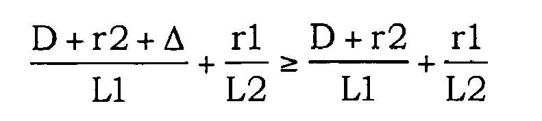
- the second optical pickup device is preferably arranged so that the first order diffractive angle represented by ⁇ satisfies: D + r ⁇ 2 + ⁇ / L ⁇ 1 + r ⁇ 1 / L ⁇ 2 ⁇ tan ⁇ ⁇ D + r ⁇ 2 / L ⁇ 1 + r ⁇ 1 / L ⁇ 2
- D represents a distance between the light source and the main and sub light receiving sections
- r1 represents a radius of the hologram element
- r2 represents a radius of an optical element closest to the hologram element
- L1 represents a distance between the optical element and the main and sub light receiving sections in a direction parallel with an optical axis of the hologram element
- L2 represents a distance between the hologram element and the main and sub light receiving sections in a direction parallel with the optical axis of the hologram element
- ⁇ represents an arrangement error of the optical element.
- a third optical pickup device in which a light beam emitted from a light source is converged onto an optical recording medium through an optical system, and a shift which a focal point of the light beam has made from the optical recording medium and a shift of the light beam in an radial direction on the optical recording medium are detected based on return light returning from the optical recording medium through the optical system, is arranged so as to comprise (1) focus control means including at least two focus-error-detection-use light receiving sections for producing a first signal in accordance with a quantity of the return light incident thereon, the focus control means producing, based on the first signal, a focus error signal in accordance with the shift of the focal point of the light beam, (2) radial control means having at least two radial-error-detection-use light receiving sections for providing a second signal in accordance with a quantity of the return light incident thereon, the radial-error-detection-use light receiving sections being provided so as to have the
- the third optical pickup device In the third optical pickup device, return light is surely received even in the case where the return light to be incident on the light receiving sections for radial error signal detection use is shifted due to an arrangement error, and moreover, the effective light receiving area can be minimized. By so doing, a difference between the respective effective light receiving areas of the light receiving sections for focus error signal detection use and that for radial error signal detection use can be made smaller, whereby deterioration of frequency characteristics is prevented. As a result, the light receiving element including both the light receiving sections is not hindered from having better frequency characteristics in a high frequency band. Further, since the effective receiving areas of the light receiving sections for the radial error signal detection use are set substantially equal to each other, the light receiving sections have the same frequency characteristics.
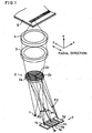
- FIGS 1 through 3 are views illustrating an arrangement of a pickup device in accordance with the first embodiment of the present invention.
- an optical disk 5 is, for example, a disk having two data layers at a sufficiently small distance (for example, 40 ⁇ m to 70 ⁇ m) as compared with a thickness of the substrate, which has been proposed as a double-layer digital versatile disk (DVD).
- a semiconductor laser 1 as a light source is diffracted by a hologram element 2, and a zeroth order diffracted light among the light thus diffracted is made to enter the objective lens 4 through a collimator lens 3, thereby being converged on the optical disk 5.
- Return light from the optical disk 5 is led to the hologram element 2 through the objective lens 4 and the collimator lens 3.
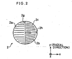
- the hologram element 2 is, as shown in Figure 2 , divided into three division regions 2a, 2b, and 2c by a dividing segment 2g extending in a y direction corresponding to a radial direction of the optical disk 5, and a dividing segment 2h extending from a center of the dividing segment 2g in an x direction which is orthogonal to the radial direction of the optical disk 5, that is, corresponds to a track direction of the optical disk 5.
- Diffraction gratings are formed so as to correspond to the division regions 2a, 2b, and 2c, respectively.
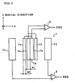
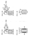
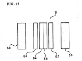
- the receiving element 7 has six rectangular light receiving sections 7a, 7b, 7c, 7d, 7e, and 7f which are juxtaposed in the x direction corresponding to the track direction of the optical disk 5.
- the light receiving sections 7a and 7b in the middle are main light receiving sections for focus error detection use, which are formed by equally dividing one rectangle into the two sections by a dividing segment 7x extending in the y direction corresponding to the radial direction of the optical disk 5.
- the light receiving sections 7e and 7f disposed beside the main light receiving sections 7a and 7b, respectively, are sub light receiving sections for focus error compensation use.
- the light receiving sections 7e and 7f are positioned symmetrically with respect to the dividing segment 7x.
- a width W1 of the main light receiving sections 7a and 7b and a width W2 of the sub light receiving sections 7e and 7f in the x direction are set so as to satisfy W1>W2.
- the light receiving sections 7c and 7d provided outermost are for radial (tracking) error detection use, and are provided at predetermined distances to the sub light receiving sections 7e and 7f in the x direction, respectively.
- Each of the light receiving sections 7a, 7b, 7c, 7d, 7e, and 7f is formed long in the y direction corresponding to the radial direction.
- the light receiving sections 7a and 7f are connected with each other, while so are the light receiving sections 7b and 7e, so that a sum signal of output signals Sa and Sf outputted by the light receiving sections 7a and 7f, and a sum signal of output signals Sb and Se outputted by the light receiving sections 7b and 7e are obtained.
- a differential amplifier 9 finds a difference between output signals of the light receiving sections 7c and 7d, and outputs a radial error signal RES.
- the radial error signal RES is outputted by finding, not a difference between output signals as above, but a phase difference (delay) of output signals.
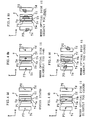
- Figures 4(a) through 4(e) are explanatory views explaining the states.
- a return light diffracted by the division region 2a of the hologram element 2 forms a light beam spot P1 on the dividing segment 7x, while return lights diffracted by the division regions 2b and 2c form light beam spots P2 and P3 on the light receiving sections 7d and 7c, respectively.
- the light beam spots P1, P2, and P3 are formed with some offsets from centers of the light receiving sections in the y direction, so that position tolerance of the light receiving element 7 or wavelength variation may be absorbed by adjusting the position of the hologram element 2.
- output signals of the main light receiving sections 7a and 7b and the sub light receiving sections 7e and 7f are zero.
- the output signals of the main light receiving sections 7a and 7b and the sub light receiving sections 7e and 7f are not zero.
- the light beam spot P1 is enlarged in the main light receiving section 7b as shown in Figure 4(b)
- the light beam spot P1 is enlarged in the main light receiving section 7a as shown in Figure 4(d) .
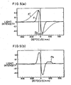
- an FES curve (F) of the control is indicated by a solid line
- an FES curve (F') in the case where the sub light receiving sections 7e and 7f are absent is indicated by a dot line.
- the FES curve F conforms to the FES curve F'.
- the focus error signal FES based on (Sa+Sf)-(Sb+Se) is sharply converged to zero immediately outside the dynamic range Dy, as shown by the solid line curve (F) in Figure 5(a) . Since the decreasing manner of the FES outside the dynamic range Dy changes by varying the shape of the light receiving sections 7e and 7f, the distances between the light receiving sections 7a and 7e and between the sections 7b and 7f, the FES curve can be rapidly converged to zero by optimizing such shapes and distances.
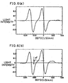
- the pickup device of the control is designed so as to be used for recording/reproducing information to/from an optical disk with a plurality of recording/reproduction layers such as a DVD (two layers)
- a satisfactory FES curve free from focus offset can be obtained from every layer, as shown in Figure 6(a) .
- the FES curve comes to have a high peak Pk, as shown in Figure 5(b) , in a region (right-hand side) in which the displacement of the optical disk is plus (hereinafter referred to as a FAR region). If such a pickup device of the control having an assembly error is used for recording/reproduction of an optical disk having a plurality of recording/reproduction layers, an FES obtained in this case has a great focus offset ⁇ f as shown in Figure 6(b) , hence it is difficult to achieve precise focalization.
- Figures 7(a) and 7(b) show a shape of a light beam spot P1 formed on the light receiving sections 7a, 7b, 7e, and 7f, and shapes of light beam spots P2 and P3 formed on the light receiving sections 7c and 7d.
- Figures 8(a) and 8(b) show signals Sa, Sb, Se, and Sf which are output signals of the light receiving sections 7a, 7b, 7e, and 7f.
- Figures 7(a) and 7(b) illustrate the light beam spots obtained in the case where the dividing segment 2g is offsetted in the +x direction, and as shown therein, the light beam spot P1 in the defocus state protrudes out to the main light receiving section 7a side by crossing the center of the light receiving element 7.
- the light beam spot P1 more greatly protrudes out from an appropriate side to the other side by crossing the dividing segment 2g, as compared with the light beam spot P1 in the case where the optical disk 5 is displaced so as to approach the objective lens excessively as shown in Figure 7(b) . If there is no assembly error, for example, no return light is made incident to the main light receiving section 7a even in the defocus state in which the optical disk is displaced so as to become farther excessively. In contrast, if there is an assembly error, return light becomes incident to the main light receiving section 7a as the defocus state is gravitated due to the assembly error.
- the output signals Sb and Sf vary as shown in Figure 8(a) .
- (Sb-Sf) becomes substantially zero in the FAR (right-hand side) region of the figure.
- (Sb-Sf) remains slightly greater than zero.
- the output signals Sa and Se vary as shown in Figure 8(b) .
- (Sa-Se) is substantially zero in the NEAR region, while it does not become zero in the FAR region in a defocus state with a displacement of not less than 10 ⁇ m, but has sufficiently greater than zero.
- (Sa-Se) is finally converged to zero in a defocus state with a displacement of not less than 20 ⁇ m.
- the FES expressed by (Sa-Se)-(Sb-Sf) has a high peak in the FAR region, while it gradually drops and becomes more or less greater than zero.
- each area (effective light receiving area) of the sub light receiving sections 7e and 7f is set smaller than each area (effective light receiving area) of the main light receiving sections 7a and 7b so as to reduce the compensation by the sub light receiving sections. Therefore, such excessive compensation can be prevented, and a satisfactory FES curve can be obtained.
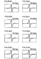
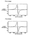
- Figures 9(a) through 9(h) show FES curves obtained when the width of the sub light receiving sections 7e and 7f is varied.
- Figures 9(a) through 9(d) show FES curves in the case where a certain assembly error occurs, while Figures 9(e) through 9(h) show FES curves when the light receiving sections are desirably assembled.
- the FES curves of Figures 9(a) and 9(e) , the FES curves of Figures 9(b) and 9(f) , the FES curves of Figures 9(c) and 9(g) , and the FES curves of Figures 9(d) and 9(h) are obtained when the width W2 of the sub light receiving sections 7e and 7f is 26 ⁇ m, 20 ⁇ m, 13 ⁇ m, and 7 ⁇ m, respectively.
- the width W1 of the main light receiving sections 7a and 7b is set to 25 ⁇ m.
- the width W2 is set to 7 ⁇ m, the focus offset in the case of desirable assembling is considerably great, and particularly when the width W2 is less than 25 percent of the width W1 of the main light receiving sections 7a and 7b, the offset seriously matters.
- the excessive compensation is prevented by forming the sub light receiving sections 7e and 7f so as to have a smaller width as compared with the width of the main light receiving sections 7a and 7b, but the arrangement of the optical pickup device of the present invention is not limited to this, and it may be arranged as follows. In the following arrangements, the width of the sub light receiving sections 7e and 7f is set substantially equal to that of the main light receiving sections 7a and 7b.
- An optical pickup device of the second embodiment is arranged so as to realize the following measure among those which are mentioned as measures for preventing excessive compensation in the description of the first embodiment: to make the light beam spot less protrude from the appropriate side to the other side by crossing the border between the main light receiving sections 7a and 7b in the case where there is an assembly error.
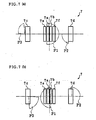
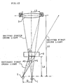
- Figure 12 shows a schematic arrangement of the optical pickup device.
- the semiconductor laser 1 the light receiving element 7, the hologram element 2, and the collimator lens 3 are shown.
- a cover glass 14 is provided in the vicinity of the hologram element 2, on a side thereof to the semiconductor laser 1.
- a diffractive angle of the hologram element 2 is set so that a first order diffracted light (returned first order light), among return light from the optical disk, is made incident onto the light receiving element 7. Further, regarding a light beam emitted from the semiconductor laser 1, not only a zeroth order light but also a first order diffracted light (emitted first order light) are also produced, going toward the collimator lens 3.
- the shape of the optical beam spot formed on the light receiving element 7 more greatly varies due to an assembly error or the like, as the diffractive angle ⁇ 1 of the hologram element 2 is greater. Therefore, to cause the light beam spot to less protrude out of the appropriate main light receiving section to the other by crossing the border therebetween, the diffractive angle ⁇ 1 may be made smaller.
- the diffractive angle ⁇ 1 is decreased too much, since in such a case the emitted first order diffracted light enters the collimator lens 3, and produces unnecessary light onto the optical disk. Therefore, by decreasing the diffractive angle to such a level that the emitted first order diffracted light does not enter optical elements behind the hologram element 2 like the collimator lens 3, a satisfactory pickup device which satisfies both the requirements can be provided.
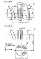
- r1 and r2 represent a radius of the hologram element 2 and a radius of the collimator lens 3, respectively, ⁇ 1 represents a diffractive angle of return light diffracted by the hologram element 2, and ⁇ 2 represents an angle at which a line connecting the light receiving element 7 and the closest position in the diffraction plane of the hologram element 2 crosses a direction parallel with the optical axis which crosses the hologram element 2.
- L1 represents a distance between the light receiving element 7 and the collimator lens 3 (distance in a direction parallel with the optical axis of the collimator lens 3)
- L2 represents a distance between the light receiving element 7 and the hologram element 2 (distance in a direction parallel with the optical axis of the hologram element 2).
- D represents a distance between the light receiving element 7 and the semiconductor laser 1 (distance in a direction parallel with a surface of the hologram element 2).
- a condition for preventing the emitted first order diffracted light from entering the collimator lens 3 can be expressed as follows: L ⁇ 1 ⁇ tan ⁇ ⁇ 2 ⁇ D + r ⁇ 2 tan ⁇ ⁇ 2 ⁇ D + r ⁇ 2 / L ⁇ 1 From the formulas (1) and (2), a condition that ⁇ 1 should satisfy is found as follows: tan ⁇ ⁇ 1 ⁇ D + r ⁇ 2 / L ⁇ 1 + r ⁇ 1 / L ⁇ 2 Therefore, by setting the diffractive angle ⁇ 1 so as to satisfy the foregoing formula, the emitted first order diffracted light does not enter the collimator lens 3.
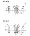
- Figures 13(a) and 13(b) show how a light beam spot (indicated by two-dot chain lines in the figures) formed on the light receiving element 7 varies when the diffractive angle of the hologram element 2 is varied to double.
- Figure 13(a) shows a light beam spot in the case where the diffractive angle is about 15°
- Figure 13(b) shows a light beam spot in the case where the diffractive angle is about 30°.
- the light beam spot protrudes less from the border between the main light receiving sections 7a and 7b to which the light beam spot is to fall on. As a result, the focus offset can be suppressed, whereby a satisfactory FES curve can be obtained.
- the compensation of the focus error signal is prevented from becoming excessive or insufficient, and consequently, stable focus control can be performed in recording/reproduction of an optical disk having a plurality of recording/reproduction layers.
- the radius r1 of the hologram element 2 is set to 0.39 mm, while a thickness of a supporter 2d of the hologram element 2 is set to 1.0 mm.
- L2 is set to 3.031 mm, while D is set to 0.8 mm.
- a distance between a light emitting point of the semiconductor laser 1 and a light receiving surface of the light receiving element 7 is set to 0.38 mm.
- a distance between a surface of the hologram element 2 on the semiconductor laser 1 side and the light receiving surface of the light receiving element is set to 2.57 mm as an optical path in the air.
- the cover glass 14 glass whose thickness is set to 0.25 mm and whose refractive index thereof is set to 1.48 is used.
- An optical pickup device of the present embodiment has light receiving sections 7c' and 7d' for radial error detection use as shown in Figures 14(a) and 14(b) , which differ in shape from the light receiving sections 7c and 7d (see Figure 3 ) for radial error detection use in the optical pickup device of the first embodiment.
- Figures 14(a) and 14(b) show shapes of light beam spots (indicated by two-dot chain lines in the figures) in the case where return light falls on the light receiving element 7 with maximum offsets in +y direction and -y direction, respectively, which are caused by an assembly error intrinsic in the optical system or the like. These figures also show the return light in a defocus state with a certain displacement.
- such light receiving sections 7c" and 7d" are formed in rectangular shapes having sides parallel with the dividing segment 7x as a border between the main light receiving sections 7a and 7b, as indicated by broken lines in the figure.
- an area of the same is remarkably greater than the area of the light receiving sections 7a, 7b, 7e, and 7f for focus error signal detection use, whereby frequency characteristics deteriorate.
- the left region and the right region of the light receiving element 7 have different frequency characteristics.
- it is important to obtain good signal characteristics in a high frequency band since a signal frequency band of the device is high, about 4 to 5 MHz.
- a level of noise contained in an output signal outputted from a light receiving section is in proportion to an area of the light receiving section. Further, since the signal level lowers as the frequency of the output signal is higher, the output signal is remarkably affected by noise. In other words, as the light receiving section has a greater area, it becomes more difficult to maintain a good S/N, and as a result, frequency characteristics deteriorate (a good S/N cannot be ensured in a high frequency band).
- stray light from a layer adjacent to a layer accessed is made incident on the light receiving element 7, and a radial offset takes place due to this stray light since the areas of the left and right regions of the light receiving element 7 are different from each other.
- a quantity of the stray light received by the light receiving element 7 is proportional to the light receiving area thereof, hence, in the case where the radial error signal is detected by detecting a difference between output signals of the light receiving sections 7c" and 7d", a difference between quantities of the stray light received by the light receiving sections 7c" and 7d" appears as a radial offset.
- the light receiving sections 7c' and 7d' have as small an area as possible, and to make the areas thereof substantially equal to each, other.
- the light receiving sections 7c' and 7d' have an equal width W3 in the x direction and an equal length L3 in the y direction.
- the width W3 is set smaller than a width W4 of the light receiving section 7c" in the x direction, and also smaller than a width W5 of the light receiving section 7c" in the x direction.
- the length L3 of the light receiving sections 7c' and 7d' is equal to the length L3 of the light receiving sections 7d" and 7d'' in the y -direction.
- the area (effective light receiving area) of the light receiving sections 7c' and 7d' is not more than half of the area of the light receiving sections 7c" and 7d" indicated by broken lines.
- Figure 15(a) shows an example of specific dimensions of the light receiving element 7
- Figure 15(b) shows an example of arrangement of the hologram element 2 and the light receiving element 7.
- the length L3, the width W3, and a distance between centers of the light receiving sections 7c' and 7d' are 244 ⁇ m, 60 ⁇ m, and 480 ⁇ m, respectively.
- the width W1 of the main light receiving sections 7a and 7b, and the width W2 of the sub light receiving sections 7e and 7f are 24.5 ⁇ m and 11 ⁇ m, respectively.
- a distance between farthest end edges of the sub light receiving sections 7e and 7f is 102 ⁇ m.
- a distance between the main light receiving sections 7a and 7b is 5 ⁇ m, while each distance between the main and sub light receiving sections 7a and 7e, and between the main and sub light receiving sections 7b and 7f, is 13 ⁇ m.
- a slant angle of the light receiving section 7c' is set to 20°
- a slant angle of the light receiving section 7d' is set to 5°.
- a distance between centers of the hologram element 2 and the light receiving element 7 in the y direction is set to 800 ⁇ m, while a distance therebetween in the x direction is set to 19.8 ⁇ m.
- the optical pickup device of the present invention is characterized in that: since the supplemental signals from the sub light receiving sections for focus error signal compensation use are adjusted, occurrence of offset to the focus error signal can be suppressed even in the case where the shape of the light beam spot varies due to an arrangement error (an assembly error or the like) of the optical element.
- the effective light receiving area of the sub light receiving sections smaller than the effective light receiving area of the main light receiving sections, compensation of the focus error signal is prevented from becoming excessive or insufficient in a great defocus state even in the case where shape variation of the light beam spot on the light receiving element including the main and sub light receiving sections is different from that in a normal state due to an arrangement error when the focus adjusting operation is carried out.
- the effective light receiving area of the sub light receiving sections is not less than 25 percent and not more than 80 percent of the effective light receiving area of the main light receiving sections, compensation of the focus error signal is prevented from becoming excessive or insufficient in a great defocus state, irrelevant to presence or absence of an arrangement error, even in the case where shape variation of the light beam spot on the light receiving element including the main and sub light receiving sections is different from that in a normal state when the focus adjusting operation is carried out.
- another optical pickup device of the present invention is arranged so that a first order diffractive angle of the hologram element is reduced to such a level that an emitted first order diffracted light is not made incident on the optical element, whereby occurrence of an offset to the focus error signal can be suppressed even in the case where the shape of the light beam spot on the light receiving element varies due to an arrangement error.
- compensation of the focus error signal is prevented from becoming excessive or insufficient. Therefore, it is possible to obtain a satisfactory FES curve upon recording/reproduction of an optical disk having a plurality of recording/reproduction layers.
- the light receiving sections for radial error signal detection use are provided at least in regions to which return light shifted due to an arrangement error is incident, in such a manner that they have a substantially equal effective light receiving area each.
- the effective light receiving areas can be made minimum, whereby the light receiving element including those for focus and radial error signal detection use can be made to have good frequency characteristic in a high frequency band.
- frequency characteristics of these light receiving sections become identical to each other. Therefore, when a reproducing operation is carried out with respect to an optical recording medium having a plurality of recording/reproduction layers, it is possible to suppress occurrence of radial offset stemming from stray light from a layer adjacent to a layer accessed.
Landscapes
- Physics & Mathematics (AREA)
- Optics & Photonics (AREA)
- Mathematical Physics (AREA)
- Optical Recording Or Reproduction (AREA)
- Optical Head (AREA)
Claims (6)
- Optische Aufnahmevorrichtung, in der ein von einer Lichtquelle (1) emittiertes Lichtstrahlenbündel auf einem optischen Aufzeichnungsmedium (5) durch ein optisches System zur Konvergenz gebracht wird und eine Verschiebung, die ein Brennpunkt des Lichtstrahlenbündels von dem optischen Aufzeichnungsmedium (5) ausgeführt hat, anhand von Rückkehrlicht detektiert wird, das von dem optischen Aufzeichnungsmedium (5) durch das optische System zurückkehrt, wobei die optische Aufnahmevorrichtung enthält:Hauptlichtempfangsmittel mit wenigstens zwei Hauptlichtempfangsabschnitten (7a, 7b), wobei jeder Hauptlichtempfangsabschnitt in Übereinstimmung mit einer Menge des darauf auftreffenden Rückkehrlichts ein Hauptsignal erzeugt;Nebenlichtempfangsmittel mit Nebenlichtempfangsabschnitten (7a, 7f), wobei jedes Nebenlichtempfangsmittel in Übereinstimmung mit einer Menge des Teils des Rückkehrlichts, das darauf auftrifft, ein Nebensignal erzeugt; undFehlersignalerzeugungsmittel (8), um ein Brennpunktfehlersignal durch Kompensieren des Hauptsignals unter Verwendung des Nebensignals zu erzeugen,dadurch gekennzeichnet, dass die Nebenlichtempfangsmittel das Nebensignal jeweils nur erzeugen, wenn die Verschiebung des Brennpunkts jenseits eines dynamischen Bereichs des Brennpunktfehlersignals liegt und das Rückkehrlicht außerdem außerhalb der Hauptlichtempfangsabschnitte (7a, 7b) und teilweise auf den Nebenlichtempfangsabschnitten (7e, 7f) auftrifft, und die Nebenlichtempfangsmittel dazu ausgelegt sind, einen Versatz des Brennpunktfehlersignals aufgrund eines Anordnungsfehlers eines das optische System bildenden optischen Elements unter Verwendung des Nebensignals einzustellen,wobei eine effektive Lichtempfangsfläche jedes Nebenlichtempfangsabschnitts (7e, 7f) kleiner gesetzt ist als eine effektive Lichtempfangsfläche jedes Hauptlichtempfangsabschnitts (7a, 7b).
- Optische Aufnahmevorrichtung nach Anspruch 1, wobei die effektive Lichtempfangsfläche jedes Nebenlichtempfangsabschnitts (7e, 7f) nicht kleiner als 25 Prozent und nicht größer als 80 Prozent der effektiven Lichtempfangsfläche jedes Hauptlichtempfangsabschnitts (7a, 7b) ist.
- Optische Aufnahmevorrichtung nach Anspruch 1, wobei die Nebenlichtempfangsmittel Pegeleinstellmittel zum Einstellen eines Pegels des Nebensignals enthalten.
- Optische Aufnahmevorrichtung, in der ein von einer Lichtquelle emittiertes Lichtstrahlenbündel dazu veranlasst wird, sich durch ein Hologrammelement (2) zu bewegen, und auf einem optischen Aufzeichnungsmedium (5) durch ein optisches Element zur Konvergenz gebracht wird und eine Verschiebung, die ein Brennpunkt des Lichtstrahlenbündels von dem optischen Aufzeichnungsmedium (5) ausgeführt hat, anhand von Rückkehrlicht detektiert wird, das von dem optischen Aufzeichnungsmedium (5) zurückkehrt und durch das Hologrammelement (2) gebeugt wird, wobei die optische Aufnahmevorrichtung enthält:Hauptlichtempfangsmittel mit wenigstens zwei Hauptlichtempfangsabschnitten, wobei jeder Hauptlichtempfangsabschnitt ein Hauptsignal in Übereinstimmung mit einer Menge des darauf auftreffenden Rückkehrlichts erzeugt, wobei das Rückkehrlicht eine Querschnittsform in Übereinstimmung mit der Verschiebung, die der Brennpunkt des Lichtstrahlenbündels von dem optischen Aufzeichnungsmedium (5) ausgeführt hat, besitzt;Nebenlichtempfangsmittel mit Nebenlichtempfangsabschnitten (7e, 7f), wobei jedes Nebenlichtempfangsmittel ein Nebensignal in Übereinstimmung mit einer Menge des Teils des darauf auftreffenden Rückkehrlichts erzeugt; undFehlersignalerzeugungsmittel (8), um durch Kompensieren des Hauptsignals durch das Nebensignal ein Brennpunktfehlersignal zu erzeugen,dadurch gekennzeichnet, dass die Nebenlichtempfangsmittel das Nebensignal jeweils nur erzeugen, wenn die Verschiebung des Brennpunkts jenseits eines dynamischen Bereichs des Brennpunktfehlersignals liegt und das Rückkehrlicht außerdem außerhalb der Hauptlichtempfangsabschnitte (7a, 7b) und teilweise auf den Nebenlichtempfangsabschnitten (7e, 7f) auftrifft, und ein Beugungswinkel erster Ordnung des Hologrammelements (2) im Wesentlichen gleich einem minimalen Beugungswinkel in einem Winkelbereich gesetzt wird, den gebeugtes Licht erster Ordnung hervorruft, das sich aus der Beugung des Lichtstrahlenbündels von der Lichtquelle durch das Hologrammelement (2) ergibt, um außerhalb eines Auftreffbereichs auf dem optischen Element anzukommen.
- Optische Aufnahmevorrichtung nach Anspruch 4, wobei der Beugungswinkel erster Ordnung, der durch 8 repräsentiert wird, erfüllt:
wobei D einen Abstand zwischen der Lichtquelle und den Haupt- und Nebenlichtempfangsabschnitten (7a, 7b, 7e, 7f) repräsentiert, r1 einen Radius des Hologrammelements (2) repräsentiert, r2 einen Radius eines optischen Elements, das sich am nächsten bei dem Hologrammelement (2) befindet, repräsentiert, L1 einen Abstand zwischen dem optischen Element und den Haupt- und Nebenlichtempfangsabschnitten (7a, 7b/7e, 7f) in einer Richtung parallel zu einer optischen Achse des Hologrammelements (2) repräsentiert, L2 einen Abstand zwischen dem Hologrammelement (2) und den Haupt- und Nebenlichtempfangsabschnitten in einer Richtung parallel zu der optischen Achse des Hologrammelements (2) repräsentiert und Δ einen Anordnungsfehler des optischen Elements repräsentiert. - Optische Aufnahmevorrichtung nach Anspruch 1, wobei auch eine Verschiebung des Lichtstrahlenbündels in einer radialen Richtung auf dem optischen Aufzeichnungsmedium (5) anhand von Rückkehrlicht, das von dem optischen Aufzeichnungsmedium (5) durch das optische System zurückkehrt, detektiert wird,
wobei die Hauptlichtempfangsmittel, die Signallichtempfangsmittel und die Fehlersignalerzeugungsmittel dazu ausgelegt sind, Brennpunktsteuermittel aufzubauen, die wenigstens zwei die Brennpunktfehlerdetektion nutzende Lichtempfangsabschnitte enthalten, um ein erstes Signal in Übereinstimmung mit einer Menge des darauf auftreffenden Rückkehrlichts zu erzeugen, wobei die Brennpunktsteuermittel anhand des ersten Signals ein Brennpunktfehlersignal in Übereinstimmung mit der Verschiebung des Brennpunkts des Lichtstrahlenbündels erzeugen;
ferner mit Radialsteuermitteln, die wenigstens zwei Lichtempfangsabschnitte mit Radialfehlerdetektionsnutzung besitzen, um in Übereinstimmung mit einer Menge des darauf auftreffenden Rückkehrlichts ein zweites Signal bereitzustellen, wobei die Lichtempfangsabschnitte mit Radialfehlerdetektionsnutzung so beschaffen sind, dass sie die dazwischen vorgesehenen Lichtempfangsabschnitte mit Brennpunktfehlerdetektionsnutzung besitzen, wobei die Radialsteuermittel anhand des zweiten Signals ein Radialfehlersignal in Übereinstimmung mit der Verschiebung des Lichtstrahlenbündels in der radialen Richtung erzeugen, wobei:die Lichtempfangsabschnitte mit Radialfehlerdetektionsnutzung wenigstens in Bereichen vorgesehen sind, auf die das Rückkehrlicht, das aufgrund eines Anordnungsfehlers eines das optische System bildenden optischen Elements verschoben ist, auftrifft; unddie Lichtempfangsabschnitte mit Radialfehlerdetektionsnutzung jeweilige effektive Lichtempfangsflächen besitzen, die im Wesentlichen einander gleich sind.
Applications Claiming Priority (3)
| Application Number | Priority Date | Filing Date | Title |
|---|---|---|---|
| JP2420397 | 1997-02-07 | ||
| JP02420397A JP3889104B2 (ja) | 1997-02-07 | 1997-02-07 | 光ピックアップ装置 |
| PCT/JP1998/000490 WO1998035346A1 (fr) | 1997-02-07 | 1998-02-06 | Dispositif de captage optique |
Publications (3)
| Publication Number | Publication Date |
|---|---|
| EP0959463A1 EP0959463A1 (de) | 1999-11-24 |
| EP0959463A4 EP0959463A4 (de) | 2008-04-02 |
| EP0959463B1 true EP0959463B1 (de) | 2011-05-04 |
Family
ID=12131768
Family Applications (1)
| Application Number | Title | Priority Date | Filing Date |
|---|---|---|---|
| EP98901528A Expired - Lifetime EP0959463B1 (de) | 1997-02-07 | 1998-02-06 | Optisches abtastgerät |
Country Status (6)
| Country | Link |
|---|---|
| US (1) | US6339562B1 (de) |
| EP (1) | EP0959463B1 (de) |
| JP (1) | JP3889104B2 (de) |
| KR (1) | KR100336958B1 (de) |
| DE (1) | DE69842255D1 (de) |
| WO (1) | WO1998035346A1 (de) |
Families Citing this family (17)
| Publication number | Priority date | Publication date | Assignee | Title |
|---|---|---|---|---|
| JP3435067B2 (ja) | 1998-08-06 | 2003-08-11 | シャープ株式会社 | 光ピックアップ装置 |
| JP2000182253A (ja) * | 1998-12-15 | 2000-06-30 | Sony Corp | 情報記録再生装置 |
| JP3549047B2 (ja) * | 2000-06-08 | 2004-08-04 | シャープ株式会社 | 光ピックアップ装置及びその収差補正方法並びに収差検出装置 |
| JP3755731B2 (ja) * | 2000-06-14 | 2006-03-15 | Tdk株式会社 | 光記録再生装置 |
| JP3827940B2 (ja) * | 2000-11-15 | 2006-09-27 | シャープ株式会社 | 収差検出装置および光ピックアップ装置 |
| JP2002157756A (ja) * | 2000-11-15 | 2002-05-31 | Sharp Corp | 焦点位置ずれ検出方法および光ピックアップ装置 |
| JP4242108B2 (ja) * | 2001-06-04 | 2009-03-18 | パナソニック株式会社 | 光ピックアップヘッドおよび情報記録再生装置 |
| US7076100B2 (en) * | 2002-09-05 | 2006-07-11 | Hi-Touch Imaging Technologies Co., Ltd. | Method and apprartus thereof for detecting a hidden image in a hologram |
| EP1939870B1 (de) * | 2003-01-29 | 2010-03-31 | Ricoh Company, Ltd. | Optische Lesekopfvorrichtung und optisches Plattengerät |
| JP4156484B2 (ja) * | 2003-09-30 | 2008-09-24 | シャープ株式会社 | 光ピックアップ |
| US8189434B2 (en) | 2004-04-30 | 2012-05-29 | Sharp Kabushiki Kaisha | Optical pickup unit and optical pickup device having same and information writing/reading device having same |
| JP4118869B2 (ja) * | 2004-11-12 | 2008-07-16 | シャープ株式会社 | 光ピックアップ装置 |
| WO2006067674A1 (en) * | 2004-12-20 | 2006-06-29 | Koninklijke Philips Electronics N.V. | Multi-spot detector arrangement for multi-layer record carriers |
| US8184519B2 (en) * | 2008-01-25 | 2012-05-22 | Sanyo Electric Co., Ltd. | Optical pickup apparatus |
| JP2009223937A (ja) * | 2008-03-14 | 2009-10-01 | Ricoh Co Ltd | 光ピックアップおよびこれを用いる光情報処理装置 |
| JP5255961B2 (ja) * | 2008-09-05 | 2013-08-07 | 株式会社日立メディアエレクトロニクス | 光ピックアップ装置および光ディスク装置 |
| JP5386198B2 (ja) * | 2009-03-09 | 2014-01-15 | 株式会社日立メディアエレクトロニクス | 光ピックアップ装置 |
Family Cites Families (14)
| Publication number | Priority date | Publication date | Assignee | Title |
|---|---|---|---|---|
| JPS609019A (ja) | 1983-06-29 | 1985-01-18 | 富士電機株式会社 | 屋外用真空しや断器 |
| JPS609019U (ja) * | 1983-06-29 | 1985-01-22 | 株式会社リコー | 光情報検出装置 |
| JPH0294119A (ja) * | 1988-09-30 | 1990-04-04 | Nippon Columbia Co Ltd | 光ピックアップ |
| JP2672620B2 (ja) * | 1989-01-12 | 1997-11-05 | 松下電器産業株式会社 | 光ヘッド装置及びその組立方法 |
| JPH083910B2 (ja) * | 1989-01-13 | 1996-01-17 | シャープ株式会社 | 光ピックアップ装置 |
| KR940001999B1 (ko) | 1989-06-06 | 1994-03-12 | 샤프 가부시끼가이샤 | 광 픽업장치 |
| JP2786496B2 (ja) * | 1990-01-12 | 1998-08-13 | 松下電器産業株式会社 | 光ヘッド装置 |
| JP2975395B2 (ja) | 1990-05-15 | 1999-11-10 | シャープ株式会社 | 光ピックアップ装置 |
| TW218427B (de) | 1991-06-04 | 1994-01-01 | Ibm | |
| JP3107892B2 (ja) * | 1992-03-04 | 2000-11-13 | シャープ株式会社 | 光学ヘッド |
| ATE168491T1 (de) * | 1992-08-12 | 1998-08-15 | Koninkl Philips Electronics Nv | Einrichtung zur optischen abtastung einer oberfläche |
| JP3209639B2 (ja) | 1994-06-21 | 2001-09-17 | 松下電器産業株式会社 | 半導体装置の製造方法 |
| JP3372413B2 (ja) * | 1995-12-04 | 2003-02-04 | シャープ株式会社 | 光ピックアップ装置及び光記録再生装置 |
| EP0831472B1 (de) * | 1996-03-11 | 2003-09-03 | Seiko Epson Corporation | Optische abtastvorrichtung und optisches aufzeichnungsgerät |
-
1997
- 1997-02-07 JP JP02420397A patent/JP3889104B2/ja not_active Expired - Lifetime
-
1998
- 1998-02-06 WO PCT/JP1998/000490 patent/WO1998035346A1/ja not_active Ceased
- 1998-02-06 KR KR1019997007106A patent/KR100336958B1/ko not_active Expired - Fee Related
- 1998-02-06 US US09/367,002 patent/US6339562B1/en not_active Expired - Lifetime
- 1998-02-06 EP EP98901528A patent/EP0959463B1/de not_active Expired - Lifetime
- 1998-02-06 DE DE69842255T patent/DE69842255D1/de not_active Expired - Lifetime
Also Published As
| Publication number | Publication date |
|---|---|
| WO1998035346A1 (fr) | 1998-08-13 |
| KR20000070841A (ko) | 2000-11-25 |
| JPH10222867A (ja) | 1998-08-21 |
| EP0959463A1 (de) | 1999-11-24 |
| US6339562B1 (en) | 2002-01-15 |
| DE69842255D1 (de) | 2011-06-16 |
| KR100336958B1 (ko) | 2002-05-15 |
| JP3889104B2 (ja) | 2007-03-07 |
| EP0959463A4 (de) | 2008-04-02 |
Similar Documents
| Publication | Publication Date | Title |
|---|---|---|
| EP0959463B1 (de) | Optisches abtastgerät | |
| EP0539354B1 (de) | Optische Abtastvorrichtung | |
| EP0777217B1 (de) | Optische Abtastvorrichtung, Aufzeichnungs-/Wiedergabegerät für eine optische Platte und Verfahren zur Erzeugung eines Fokussierungsfehlersignals | |
| JP3977234B2 (ja) | 光ピックアップ | |
| EP1215668B1 (de) | Optische Abtastvorrichtung fähig sphärische Aberration zu detektieren und/oder zu korrigieren | |
| US7035193B2 (en) | Objective lens for optical disc | |
| EP1575038A1 (de) | Optischer kopf und optische vorrichtung mit optischem kopf | |
| US7042819B2 (en) | Optical pickup apparatus | |
| US6167017A (en) | Optical head assembly having means for detecting tracking errors based on astigmatisms generated by returning beams | |
| EP0978828B1 (de) | Optische Abtastvorrichtung | |
| US7697401B2 (en) | Optical head device and optical disk apparatus | |
| JP2000011418A (ja) | ホログラムレーザユニット及びそれを使用した光ピックアップ装置 | |
| PL180658B1 (pl) | U rzadzenie do wybierania warstw informacji w optycznym nosniku zapisu PL PL | |
| US20040257960A1 (en) | Optical pick-up apparatus | |
| US7839731B2 (en) | Optical system for optical disc | |
| US6292441B1 (en) | Optical head device, optical information apparatus, and method for detecting focus error signal | |
| JP4699317B2 (ja) | 光ピックアップ装置 | |
| US7136409B2 (en) | Semiconductor laser device and optical pickup device | |
| US6167004A (en) | Error signal detecting apparatus of optical pickup adopting hologram grating | |
| JP4160411B2 (ja) | 光集積化ユニットおよびそれを備えた光ピックアップ装置 | |
| JP4004905B2 (ja) | 光集積化ユニット及び光ピックアップ装置 | |
| JPH11232665A (ja) | 光ピックアップ装置及び光ディスク装置 | |
| JP2004047092A (ja) | ホログラムレーザユニット及びそれを使用した光ピックアップ装置 |
Legal Events
| Date | Code | Title | Description |
|---|---|---|---|
| PUAI | Public reference made under article 153(3) epc to a published international application that has entered the european phase |
Free format text: ORIGINAL CODE: 0009012 |
|
| 17P | Request for examination filed |
Effective date: 19990907 |
|
| AK | Designated contracting states |
Kind code of ref document: A1 Designated state(s): DE FR GB |
|
| A4 | Supplementary search report drawn up and despatched |
Effective date: 20080305 |
|
| 17Q | First examination report despatched |
Effective date: 20081105 |
|
| GRAP | Despatch of communication of intention to grant a patent |
Free format text: ORIGINAL CODE: EPIDOSNIGR1 |
|
| GRAS | Grant fee paid |
Free format text: ORIGINAL CODE: EPIDOSNIGR3 |
|
| GRAA | (expected) grant |
Free format text: ORIGINAL CODE: 0009210 |
|
| AK | Designated contracting states |
Kind code of ref document: B1 Designated state(s): DE FR GB |
|
| REG | Reference to a national code |
Ref country code: GB Ref legal event code: FG4D |
|
| REF | Corresponds to: |
Ref document number: 69842255 Country of ref document: DE Date of ref document: 20110616 Kind code of ref document: P |
|
| REG | Reference to a national code |
Ref country code: DE Ref legal event code: R096 Ref document number: 69842255 Country of ref document: DE Effective date: 20110616 |
|
| PLBE | No opposition filed within time limit |
Free format text: ORIGINAL CODE: 0009261 |
|
| STAA | Information on the status of an ep patent application or granted ep patent |
Free format text: STATUS: NO OPPOSITION FILED WITHIN TIME LIMIT |
|
| 26N | No opposition filed |
Effective date: 20120207 |
|
| PGFP | Annual fee paid to national office [announced via postgrant information from national office to epo] |
Ref country code: FR Payment date: 20120214 Year of fee payment: 15 |
|
| PGFP | Annual fee paid to national office [announced via postgrant information from national office to epo] |
Ref country code: DE Payment date: 20120228 Year of fee payment: 15 |
|
| REG | Reference to a national code |
Ref country code: DE Ref legal event code: R097 Ref document number: 69842255 Country of ref document: DE Effective date: 20120207 |
|
| PGFP | Annual fee paid to national office [announced via postgrant information from national office to epo] |
Ref country code: GB Payment date: 20120201 Year of fee payment: 15 |
|
| GBPC | Gb: european patent ceased through non-payment of renewal fee |
Effective date: 20130206 |
|
| REG | Reference to a national code |
Ref country code: FR Ref legal event code: ST Effective date: 20131031 |
|
| REG | Reference to a national code |
Ref country code: DE Ref legal event code: R119 Ref document number: 69842255 Country of ref document: DE Effective date: 20130903 |
|
| PG25 | Lapsed in a contracting state [announced via postgrant information from national office to epo] |
Ref country code: GB Free format text: LAPSE BECAUSE OF NON-PAYMENT OF DUE FEES Effective date: 20130206 Ref country code: DE Free format text: LAPSE BECAUSE OF NON-PAYMENT OF DUE FEES Effective date: 20130903 Ref country code: FR Free format text: LAPSE BECAUSE OF NON-PAYMENT OF DUE FEES Effective date: 20130228 |