EP0958995A2 - Elément de paroi de carrosserie pour véhicule et procédé de fabrication d'un élément pareil - Google Patents
Elément de paroi de carrosserie pour véhicule et procédé de fabrication d'un élément pareil Download PDFInfo
- Publication number
- EP0958995A2 EP0958995A2 EP99108881A EP99108881A EP0958995A2 EP 0958995 A2 EP0958995 A2 EP 0958995A2 EP 99108881 A EP99108881 A EP 99108881A EP 99108881 A EP99108881 A EP 99108881A EP 0958995 A2 EP0958995 A2 EP 0958995A2
- Authority
- EP
- European Patent Office
- Prior art keywords
- wall element
- plate segments
- clasp
- angled
- edges
- Prior art date
- Legal status (The legal status is an assumption and is not a legal conclusion. Google has not performed a legal analysis and makes no representation as to the accuracy of the status listed.)
- Granted
Links
- 238000004519 manufacturing process Methods 0.000 title claims description 14
- 238000000034 method Methods 0.000 title claims description 4
- 239000000853 adhesive Substances 0.000 claims description 24
- 230000001070 adhesive effect Effects 0.000 claims description 24
- 239000011324 bead Substances 0.000 claims description 13
- 239000000463 material Substances 0.000 claims description 12
- 210000001503 joint Anatomy 0.000 claims description 5
- 239000004033 plastic Substances 0.000 claims description 5
- 229920003023 plastic Polymers 0.000 claims description 5
- 239000008259 solid foam Substances 0.000 claims 1
- 238000004026 adhesive bonding Methods 0.000 description 7
- 238000005452 bending Methods 0.000 description 7
- 239000003292 glue Substances 0.000 description 6
- 239000002184 metal Substances 0.000 description 5
- 239000006260 foam Substances 0.000 description 3
- 239000010410 layer Substances 0.000 description 3
- 239000007858 starting material Substances 0.000 description 3
- 230000007704 transition Effects 0.000 description 3
- 239000008186 active pharmaceutical agent Substances 0.000 description 2
- 239000012790 adhesive layer Substances 0.000 description 2
- 230000015572 biosynthetic process Effects 0.000 description 2
- 239000002131 composite material Substances 0.000 description 2
- 238000005260 corrosion Methods 0.000 description 2
- 230000007797 corrosion Effects 0.000 description 2
- 230000008878 coupling Effects 0.000 description 2
- 238000010168 coupling process Methods 0.000 description 2
- 238000005859 coupling reaction Methods 0.000 description 2
- 238000006073 displacement reaction Methods 0.000 description 2
- 238000005187 foaming Methods 0.000 description 2
- 239000003365 glass fiber Substances 0.000 description 2
- 238000009825 accumulation Methods 0.000 description 1
- 239000011248 coating agent Substances 0.000 description 1
- 238000000576 coating method Methods 0.000 description 1
- 238000011161 development Methods 0.000 description 1
- 230000018109 developmental process Effects 0.000 description 1
- 230000000694 effects Effects 0.000 description 1
- 238000005516 engineering process Methods 0.000 description 1
- 230000002349 favourable effect Effects 0.000 description 1
- 239000011152 fibreglass Substances 0.000 description 1
- 239000011810 insulating material Substances 0.000 description 1
- 239000000203 mixture Substances 0.000 description 1
- 230000003287 optical effect Effects 0.000 description 1
- 239000002984 plastic foam Substances 0.000 description 1
- 238000003825 pressing Methods 0.000 description 1
- 230000001737 promoting effect Effects 0.000 description 1
- 238000005096 rolling process Methods 0.000 description 1
- 238000007789 sealing Methods 0.000 description 1
- 229910001220 stainless steel Inorganic materials 0.000 description 1
- 239000010935 stainless steel Substances 0.000 description 1
- 238000004381 surface treatment Methods 0.000 description 1
- 230000000007 visual effect Effects 0.000 description 1
Images


Classifications
-
- B—PERFORMING OPERATIONS; TRANSPORTING
- B62—LAND VEHICLES FOR TRAVELLING OTHERWISE THAN ON RAILS
- B62D—MOTOR VEHICLES; TRAILERS
- B62D29/00—Superstructures, understructures, or sub-units thereof, characterised by the material thereof
- B62D29/04—Superstructures, understructures, or sub-units thereof, characterised by the material thereof predominantly of synthetic material
- B62D29/043—Superstructures
- B62D29/045—Van bodies composed of substantially rectangular panels
-
- B—PERFORMING OPERATIONS; TRANSPORTING
- B62—LAND VEHICLES FOR TRAVELLING OTHERWISE THAN ON RAILS
- B62D—MOTOR VEHICLES; TRAILERS
- B62D33/00—Superstructures for load-carrying vehicles
- B62D33/04—Enclosed load compartments ; Frameworks for movable panels, tarpaulins or side curtains
- B62D33/046—Enclosed load compartments ; Frameworks for movable panels, tarpaulins or side curtains built up with flat self-supporting panels; Fixed connections between panels
Definitions
- the invention relates to a wall element for a vehicle body and a Process for producing such a wall element.
- Wall elements in particular, are used for refrigerated vehicles opposite cover surfaces by a core of hardened Foam are interconnected as a heat insulating material.
- DE-OS 19 14 997 describes such a foamed wall element, which is made up of several wall parts. Each wall part points Side edges with a groove or a tongue and adjacent wall parts are made of tongue and groove with the interposition of a hardened mat glass fiber reinforced plastic joined together.
- EP 0 607 575 A1 discloses a kit for a box body of a vehicle, in which, among other things, wall elements are used that made up of wall parts with a plastic core and cover layers on both sides are, adjacent parts again with tongue and groove are provided, which snap together resiliently.
- the invention has for its object an advantageous wall element for a vehicle body and a method for producing such a wall element specify.
- the wall element according to the invention shows through the hollow web of the bar profile and the angled edges of the plate segments provide high rigidity against deflection along the abutting edges of adjacent plate segments and due to the side flags a high resistance to displacement neighboring plate segments along the abutting edges like a Shear of the wall element made up of several segments.
- the bond becomes a high backlash-free holding force of opposing surfaces reached from the clasp profile and plate segment without the material structure disturb.
- the bonding is also advantageous in terms of production technology.
- a two-component adhesive is used for bonding.
- the clasp profiles advantageously have essentially parallel inner surfaces of the hollow bar with the angled edges of the plate segments form a composite of a total of four parallel sheet layers, the high stability against vertical deflection in the plane of the surfaces having.
- the outer visible surface of the wall element is determined solely by the surface of the plate segments in the manufacturing process is not subject to any particular stress.
- the plate segments can with the simple shape of a flat top surface with inside angled edges advantageously with little effort flat starting material, for example made of metal or glass fiber reinforced sheet metal Plastic are made. By bending the edges the panel segments are also the most susceptible to corrosion-prone edges of the sheets forming the plate segments are additionally protected and in the event of corrosion not visually impairing.
- the side flags are provided in particular of the clasp profiles with bulging away from the flat surface of the plate segments Sections.
- arched sections are preferably as beads or grooves running parallel to the longitudinal direction of the profile or the like. Which face away from the inner surface of the plate segments and form flat channels filled with adhesive in the longitudinal direction of the profile.
- a reliable bond also results in the apex of the hollow web of the Clasp profile, in which so much adhesive is specified that this is not only the apex of the hollow web with the end edges of the bent edges of the panel segments, but also a little bit into the butt joint can penetrate between the abutting edges.
- the clasp profiles can advantageously be made from sheet metal Bending, rolling or the like. And can be made according to material thickness and Material composition preferably a much higher strength have, in particular a much higher bending stiffness than that Material of the plate segments.
- the clasp profiles can be made in particular a stainless steel sheet. This can ensure that the The clip does not tear at the sheet metal joint under load.
- the plate segment PS outlined in cross section in FIG. 1 is made of a flat one Starting material, in particular a roll material by bending manufactured by edge sections PR and extends with constant Cross section perpendicular to the drawing plane of Fig. 1.
- Such a plate segment is typically in a finished wall structure with its longitudinal direction arranged vertically.
- the starting material for the plate segment is, for example, a metallic one Sheet metal or a glass fiber reinforced plate, for example 0.5 - 2 mm Thickness.
- An outer surface OA of the plate segment is preferably with provide a coating, which requirements for visual appearance, Scratch resistance, weather resistance, corrosion protection, heat reflection etc. can meet.
- the inner surface of the plate segment Depending on the base material of the plate segment, it can be coated with an anti-corrosive Surface treatment and / or with an adhesion promoting layer for the insulating foam to be introduced later in the wall space be.
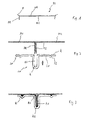
- the plate segments are in the Fig. 2 for two plate segments PS1 and PS2 outlined type with its bent edge sections PR and aligned butted outer surfaces.
- a clip profile SP with one Hollow bar HS and side flags SF are used to attach them to each other angled sections PR prepared by gluing K in the hollow bar HS and on the surface of the plate segments facing the Side flags SF is applied.
- the clasp profiles SP extend like the plate segments PS1, PS2 with their longitudinal direction perpendicular to the plane of the drawing 2 preferably in one piece over the entire length of the plate segments perpendicular to the plane of the drawing. The exact shape of the clasp profiles SP is explained in different variants below. In the example in Fig. 2 are clasp profiles SP with beads SI in the side flags SF shown.
- the sheet thickness of the clasp profiles can preferably between 0.5 times and 4 times the sheet thickness of the plate segments lie.
- the clasp profile SP is in the direction sketched by an arrow in FIG. 2 with the hollow bar HS over the collided angled Margins PR of the plate segments PS1 and PS2 pushed and with the side flags SF pressed against the inner surface OI of the plate segments.
- adhesive material K is introduced into the hollow web in such excess that at complete the clipped profile, possibly stripped adhesive material back in the space between the inner wall of the hollow web and the inner surface the angled edge sections PR is pushed.
- the Bulges can then parallel parallel flat channels filled with adhesive form to the longitudinal direction of the clasp profiles.
- the bulges are not necessarily extends in the longitudinal direction, but for reasons of simplified Production of the bar profiles as longitudinal profiles with the same Cross section designed as constant bulges in the longitudinal direction.
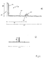
- Positions with guaranteed adhesive fillings in a high holding force ensuring thickness can also at the kinks of the plate segments and the clasp profile can be given if, for example, the bending radius is on the inner fold line of the plate segments at the transition from the flat Cover surface to the angled edge areas is significantly less than that outer bending radius of the clasp profile at the transition from the side walls of the ridge to the side flags. Then forms in the angular range longitudinal channel KW filled with adhesive, which reliably has a high holding force can apply and both in correspondence with the gluing points KS as well as with the glue points KH a favorable position in cross section of the glued Takes up order.
- the hollow bridge HS has essentially parallel side walls.
- the inner height HH of the Hollow bar from the adhesive surface of the side flags to the apex of the hollow bar is, for example, in the range from 1 mm to 20 mm or between 1% and 60%, preferably between 2% and 20% of the wall thickness of the one to be produced Wall element.
- the longitudinal bead in the side flags SF is designed as a semicircular bead RS, with a Bead depth HR in the range from 0.1 mm to 2 mm.
- the distance DS from the center of the beads from the center line ML is denoted by DS and lies, for example, in Range between 3 mm and 30 mm with a total length LF of the side flags FF based on the center line ML in the range from 5 mm to 50 mm.
- the Range specifications are only to be understood as preferred illustrative examples, depending on the dimensions of the wall structure and the individual panel segments can still vary.
- 4b is an overall view of the cross section given the clasp profile on a reduced scale.
- FIG. 5 shows various exemplary embodiments for advantageous cross-sectional shapes given the clasp profile.
- the clasp profile in cross-section an angling of the outer Edges of the side flags in the form of webs SA, which have an additional stiffening function against vertical deflection of the composite Own wall element.
- 5b shows a profile cross section in which the longitudinal bead has an approximately triangular cross section and again the edges of the side flags are angled inwards.
- the longitudinal bead has an approximately rectangular cross section.
- a profile step ST is provided, which of the middle plane extends outward over a distance DT.
- the cross section of the clasp profile is still a large number of others Shapes conceivable, especially combinations of the outlined Designs and / or designs with several parallel beads inside a side flag, bulges, not extending in the longitudinal direction, etc., which are known per se to the person skilled in the art and depending on the application and production process can be advantageous for the clasp profiles.
- FIG. 6 shows a structure of a wall element WE, which essentially from an outer cover plate WA and an inner cover plate WI as well an intermediate insulating core SK consists of hard foam.
- the Cover plates WA and WI in turn are made up of a plurality of abutting ones and connected in the manner described via clasp profiles SP Plate segments built up.
- the cover plates WA and WI in the manner outlined in FIGS. 1 to 3 made separately and spaced from each other in a plate press inserted.
- the space between the cover plates WA and WI is filled with a hardening plastic foam, the plate press absorbs the pressure that occurs during foaming and the cover plates WA and WI are kept at a defined distance.
- One of the two cover plates WE or WA can also be executed differently constructed, in particular be designed as a one-piece plate.
- the segments a cover plate are not necessarily the same width.
- the beads in the side flags of the clasp profiles be shaped in many ways, for example as grooves, or the Side flags can have flat adhesive surfaces.
- the folded edges abutting plate segments can on the mutually facing Surfaces can also be glued flat, which creates tensile forces that lead to a Bending he could lead clasp, is counteracted.
Applications Claiming Priority (2)
| Application Number | Priority Date | Filing Date | Title |
|---|---|---|---|
| DE19822884A DE19822884A1 (de) | 1998-05-22 | 1998-05-22 | Wandelement für einen Fahrzeugaufbau und Verfahren zur Herstellung eines solchen Wandelements |
| DE19822884 | 1998-05-22 |
Publications (3)
| Publication Number | Publication Date |
|---|---|
| EP0958995A2 true EP0958995A2 (fr) | 1999-11-24 |
| EP0958995A3 EP0958995A3 (fr) | 2000-07-12 |
| EP0958995B1 EP0958995B1 (fr) | 2003-03-05 |
Family
ID=7868573
Family Applications (1)
| Application Number | Title | Priority Date | Filing Date |
|---|---|---|---|
| EP99108881A Expired - Lifetime EP0958995B1 (fr) | 1998-05-22 | 1999-05-05 | Elément de paroi de carrosserie pour véhicule et procédé de fabrication d'un élément pareil |
Country Status (4)
| Country | Link |
|---|---|
| EP (1) | EP0958995B1 (fr) |
| AT (1) | ATE233688T1 (fr) |
| DE (2) | DE19822884A1 (fr) |
| PL (1) | PL333201A1 (fr) |
Cited By (2)
| Publication number | Priority date | Publication date | Assignee | Title |
|---|---|---|---|---|
| EP1415898A3 (fr) * | 2002-11-02 | 2004-11-10 | ArvinMeritor GmbH | Pièce plane de carosserie |
| DE10103077B4 (de) * | 2001-01-24 | 2008-02-14 | Schmitz Cargobull Ag | Eckabschlussanordnung für einen Koffer-Fahrzeugaufbau |
Families Citing this family (1)
| Publication number | Priority date | Publication date | Assignee | Title |
|---|---|---|---|---|
| DE102018129602B4 (de) * | 2018-11-23 | 2023-03-23 | Kögel Trailer GmbH | Isolierpaneel, Komponente eines Fahrzeugaufbaus, Fahrzeugaufbau, Fahrzeug und Herstellungsverfahren |
Citations (3)
| Publication number | Priority date | Publication date | Assignee | Title |
|---|---|---|---|---|
| DE1914997A1 (de) | 1968-03-26 | 1969-10-16 | Norcem Fa As | Karosserie aus miteinander verbundenen Kunststoffwandteilen und Verfahren zur Herstellung der Fahrzeugkarosserie |
| DE2848774A1 (de) | 1978-11-10 | 1980-05-22 | Ackermann Fruehauf | Wandelement |
| EP0607575A1 (fr) | 1993-01-21 | 1994-07-27 | Kögel Fahrzeugwerke Aktiengesellschaft | Jeu d'éléments pour carrosserie de fourgon |
Family Cites Families (3)
| Publication number | Priority date | Publication date | Assignee | Title |
|---|---|---|---|---|
| DE522732C (de) * | 1929-04-12 | 1932-05-18 | Hans Arquint | Fahrzeugwagenkasten |
| CH469594A (de) * | 1965-05-03 | 1969-03-15 | Koegel Gmbh Fahrzeug | Behälter- oder Kastenaufbau, insbesondere für Kraftfahrzeuge |
| GB2223712B (en) * | 1988-09-23 | 1992-10-14 | York Trailer Co Ltd | Improvements in and relating to thermally insulated containers |
-
1998
- 1998-05-22 DE DE19822884A patent/DE19822884A1/de not_active Withdrawn
-
1999
- 1999-05-05 EP EP99108881A patent/EP0958995B1/fr not_active Expired - Lifetime
- 1999-05-05 AT AT99108881T patent/ATE233688T1/de not_active IP Right Cessation
- 1999-05-05 DE DE59904417T patent/DE59904417D1/de not_active Expired - Lifetime
- 1999-05-18 PL PL99333201A patent/PL333201A1/xx unknown
Patent Citations (3)
| Publication number | Priority date | Publication date | Assignee | Title |
|---|---|---|---|---|
| DE1914997A1 (de) | 1968-03-26 | 1969-10-16 | Norcem Fa As | Karosserie aus miteinander verbundenen Kunststoffwandteilen und Verfahren zur Herstellung der Fahrzeugkarosserie |
| DE2848774A1 (de) | 1978-11-10 | 1980-05-22 | Ackermann Fruehauf | Wandelement |
| EP0607575A1 (fr) | 1993-01-21 | 1994-07-27 | Kögel Fahrzeugwerke Aktiengesellschaft | Jeu d'éléments pour carrosserie de fourgon |
Cited By (3)
| Publication number | Priority date | Publication date | Assignee | Title |
|---|---|---|---|---|
| DE10103077B4 (de) * | 2001-01-24 | 2008-02-14 | Schmitz Cargobull Ag | Eckabschlussanordnung für einen Koffer-Fahrzeugaufbau |
| EP1415898A3 (fr) * | 2002-11-02 | 2004-11-10 | ArvinMeritor GmbH | Pièce plane de carosserie |
| US6974179B2 (en) | 2002-11-02 | 2005-12-13 | Arvinmeritor Gmbh | Vehicle bodywork component |
Also Published As
| Publication number | Publication date |
|---|---|
| PL333201A1 (en) | 1999-12-06 |
| ATE233688T1 (de) | 2003-03-15 |
| EP0958995A3 (fr) | 2000-07-12 |
| DE19822884A1 (de) | 1999-11-25 |
| DE59904417D1 (de) | 2003-04-10 |
| EP0958995B1 (fr) | 2003-03-05 |
Similar Documents
| Publication | Publication Date | Title |
|---|---|---|
| WO2009150065A1 (fr) | Profilé en forme de baguette et procédé de fabrication de celui-ci ainsi que guide d’extraction muni d’un tel profilé | |
| DE102006012373B3 (de) | Breitschlitzdüse und Verfahren zum Auftragen von hochviskosem Material | |
| DE3146414T1 (de) | Roofing sheet and foof construction comprising of such sheets | |
| CH704363A1 (de) | Verbundprofil für Fenster, Türen und Fassaden sowie Verfahren zu dessen Herstellung. | |
| DE1914997A1 (de) | Karosserie aus miteinander verbundenen Kunststoffwandteilen und Verfahren zur Herstellung der Fahrzeugkarosserie | |
| DE102011121381B4 (de) | Verfahren zur Herstellung eines Aufprallquerträgers sowie Aufprallquerträger | |
| DE2234704A1 (de) | Wabenstruktur | |
| AT509993B1 (de) | Stossstelle zwischen den enden vorgefertigter abstandhalter für isolierglas und verfahren zum herstellen derselben | |
| DE10110996B4 (de) | Wandelement für eine Ladegutsicherungsvorrichtung und Verfahren zu dessen Herstellung | |
| EP0958995B1 (fr) | Elément de paroi de carrosserie pour véhicule et procédé de fabrication d'un élément pareil | |
| EP0358930B1 (fr) | Panneau de construction léger composé de modules plats | |
| DE69828259T2 (de) | Verfahren zur Herstellung eines Verbundelementes für hochfeste Wände und Abdeckungen | |
| DE102020101975A1 (de) | Metallband | |
| DE3937561A1 (de) | Profilleiste, insbesondere fuer fahrzeuge | |
| DE2622905A1 (de) | Rolladenstab und verfahren zu seiner herstellung | |
| DE4323922A1 (de) | Wabenstruktur, vorzugsweise für ein plattenförmiges Verbundmaterial, Verbundmaterial sowie Verfahren zur Herstellung eine solchen Verbundmaterials | |
| DE112019001609T5 (de) | Platte zur Herstellung von Schalungshaltewänden für Betonguss, insbesondere für Halteschalungen zur Herstellung von Betondecken oder dergleichen und Verfahren zur Herstellung dieser Platte | |
| DE69915032T2 (de) | Verfahren zur herstellung eines sandwichelements und kernmaterial hierfür | |
| EP2185774B1 (fr) | Structure portante pour éléments de construction légère | |
| DE19611413C2 (de) | Schalplatte für Betonschalungen mit Kantenschutz und Eckverstärkung | |
| AT160664B (de) | Biegbare, mit Metallüberzug versehene Leisten. | |
| DE10255999A1 (de) | Längsgesickter Dachlängsträger für ein Kraftfahrzeug | |
| DE2626868C3 (de) | Thermisch isolierendes Verbundprofil | |
| DE102008059152A1 (de) | Verbindungsknoten für ein Fahrzeug | |
| DE10217190A1 (de) | Profilplatte zum Eindecken eines Gebäudedachs sowie Gebäudedach |
Legal Events
| Date | Code | Title | Description |
|---|---|---|---|
| PUAI | Public reference made under article 153(3) epc to a published international application that has entered the european phase |
Free format text: ORIGINAL CODE: 0009012 |
|
| AK | Designated contracting states |
Kind code of ref document: A2 Designated state(s): AT BE CH CY DE DK ES FI FR GB GR IE IT LI LU MC NL PT SE |
|
| AX | Request for extension of the european patent |
Free format text: AL;LT;LV;MK;RO;SI |
|
| PUAL | Search report despatched |
Free format text: ORIGINAL CODE: 0009013 |
|
| AK | Designated contracting states |
Kind code of ref document: A3 Designated state(s): AT BE CH CY DE DK ES FI FR GB GR IE IT LI LU MC NL PT SE |
|
| AX | Request for extension of the european patent |
Free format text: AL;LT;LV;MK;RO;SI |
|
| 17P | Request for examination filed |
Effective date: 20000607 |
|
| AKX | Designation fees paid |
Free format text: AT BE CH CY DE DK ES FI FR GB GR IE IT LI LU MC NL PT SE |
|
| 17Q | First examination report despatched |
Effective date: 20020405 |
|
| GRAH | Despatch of communication of intention to grant a patent |
Free format text: ORIGINAL CODE: EPIDOS IGRA |
|
| GRAH | Despatch of communication of intention to grant a patent |
Free format text: ORIGINAL CODE: EPIDOS IGRA |
|
| GRAA | (expected) grant |
Free format text: ORIGINAL CODE: 0009210 |
|
| RBV | Designated contracting states (corrected) |
Designated state(s): AT BE CH DE DK ES FI FR GB GR IE IT LI LU NL PT SE |
|
| AK | Designated contracting states |
Designated state(s): AT BE CH DE DK ES FI FR GB GR IE IT LI LU NL PT SE |
|
| PG25 | Lapsed in a contracting state [announced via postgrant information from national office to epo] |
Ref country code: NL Free format text: LAPSE BECAUSE OF FAILURE TO SUBMIT A TRANSLATION OF THE DESCRIPTION OR TO PAY THE FEE WITHIN THE PRESCRIBED TIME-LIMIT Effective date: 20030305 Ref country code: IE Free format text: LAPSE BECAUSE OF FAILURE TO SUBMIT A TRANSLATION OF THE DESCRIPTION OR TO PAY THE FEE WITHIN THE PRESCRIBED TIME-LIMIT Effective date: 20030305 Ref country code: GR Free format text: LAPSE BECAUSE OF FAILURE TO SUBMIT A TRANSLATION OF THE DESCRIPTION OR TO PAY THE FEE WITHIN THE PRESCRIBED TIME-LIMIT Effective date: 20030305 Ref country code: FI Free format text: LAPSE BECAUSE OF FAILURE TO SUBMIT A TRANSLATION OF THE DESCRIPTION OR TO PAY THE FEE WITHIN THE PRESCRIBED TIME-LIMIT Effective date: 20030305 |
|
| REG | Reference to a national code |
Ref country code: GB Ref legal event code: FG4D Free format text: NOT ENGLISH |
|
| REG | Reference to a national code |
Ref country code: CH Ref legal event code: NV Representative=s name: RIEDERER HASLER & PARTNER PATENTANWAELTE AG Ref country code: CH Ref legal event code: EP |
|
| REG | Reference to a national code |
Ref country code: IE Ref legal event code: FG4D Free format text: GERMAN |
|
| REF | Corresponds to: |
Ref document number: 59904417 Country of ref document: DE Date of ref document: 20030410 Kind code of ref document: P |
|
| PG25 | Lapsed in a contracting state [announced via postgrant information from national office to epo] |
Ref country code: LU Free format text: LAPSE BECAUSE OF NON-PAYMENT OF DUE FEES Effective date: 20030505 |
|
| PG25 | Lapsed in a contracting state [announced via postgrant information from national office to epo] |
Ref country code: BE Free format text: LAPSE BECAUSE OF NON-PAYMENT OF DUE FEES Effective date: 20030531 |
|
| PG25 | Lapsed in a contracting state [announced via postgrant information from national office to epo] |
Ref country code: SE Free format text: LAPSE BECAUSE OF FAILURE TO SUBMIT A TRANSLATION OF THE DESCRIPTION OR TO PAY THE FEE WITHIN THE PRESCRIBED TIME-LIMIT Effective date: 20030605 Ref country code: PT Free format text: LAPSE BECAUSE OF FAILURE TO SUBMIT A TRANSLATION OF THE DESCRIPTION OR TO PAY THE FEE WITHIN THE PRESCRIBED TIME-LIMIT Effective date: 20030605 Ref country code: DK Free format text: LAPSE BECAUSE OF FAILURE TO SUBMIT A TRANSLATION OF THE DESCRIPTION OR TO PAY THE FEE WITHIN THE PRESCRIBED TIME-LIMIT Effective date: 20030605 |
|
| GBT | Gb: translation of ep patent filed (gb section 77(6)(a)/1977) | ||
| NLV1 | Nl: lapsed or annulled due to failure to fulfill the requirements of art. 29p and 29m of the patents act | ||
| ET | Fr: translation filed | ||
| PG25 | Lapsed in a contracting state [announced via postgrant information from national office to epo] |
Ref country code: ES Free format text: LAPSE BECAUSE OF FAILURE TO SUBMIT A TRANSLATION OF THE DESCRIPTION OR TO PAY THE FEE WITHIN THE PRESCRIBED TIME-LIMIT Effective date: 20030930 |
|
| REG | Reference to a national code |
Ref country code: IE Ref legal event code: FD4D Ref document number: 0958995E Country of ref document: IE |
|
| BERE | Be: lapsed |
Owner name: *KIESLING PETER Effective date: 20030531 |
|
| PLBE | No opposition filed within time limit |
Free format text: ORIGINAL CODE: 0009261 |
|
| STAA | Information on the status of an ep patent application or granted ep patent |
Free format text: STATUS: NO OPPOSITION FILED WITHIN TIME LIMIT |
|
| 26N | No opposition filed |
Effective date: 20031208 |
|
| PGFP | Annual fee paid to national office [announced via postgrant information from national office to epo] |
Ref country code: CH Payment date: 20080523 Year of fee payment: 10 |
|
| PGFP | Annual fee paid to national office [announced via postgrant information from national office to epo] |
Ref country code: AT Payment date: 20080521 Year of fee payment: 10 |
|
| PGFP | Annual fee paid to national office [announced via postgrant information from national office to epo] |
Ref country code: IT Payment date: 20080524 Year of fee payment: 10 |
|
| PGFP | Annual fee paid to national office [announced via postgrant information from national office to epo] |
Ref country code: GB Payment date: 20080522 Year of fee payment: 10 |
|
| REG | Reference to a national code |
Ref country code: CH Ref legal event code: PL |
|
| GBPC | Gb: european patent ceased through non-payment of renewal fee |
Effective date: 20090505 |
|
| PG25 | Lapsed in a contracting state [announced via postgrant information from national office to epo] |
Ref country code: LI Free format text: LAPSE BECAUSE OF NON-PAYMENT OF DUE FEES Effective date: 20090531 Ref country code: CH Free format text: LAPSE BECAUSE OF NON-PAYMENT OF DUE FEES Effective date: 20090531 Ref country code: AT Free format text: LAPSE BECAUSE OF NON-PAYMENT OF DUE FEES Effective date: 20090505 |
|
| REG | Reference to a national code |
Ref country code: FR Ref legal event code: ST Effective date: 20100129 |
|
| PG25 | Lapsed in a contracting state [announced via postgrant information from national office to epo] |
Ref country code: FR Free format text: LAPSE BECAUSE OF NON-PAYMENT OF DUE FEES Effective date: 20090602 |
|
| PGFP | Annual fee paid to national office [announced via postgrant information from national office to epo] |
Ref country code: FR Payment date: 20080519 Year of fee payment: 10 |
|
| PG25 | Lapsed in a contracting state [announced via postgrant information from national office to epo] |
Ref country code: GB Free format text: LAPSE BECAUSE OF NON-PAYMENT OF DUE FEES Effective date: 20090505 |
|
| PG25 | Lapsed in a contracting state [announced via postgrant information from national office to epo] |
Ref country code: IT Free format text: LAPSE BECAUSE OF NON-PAYMENT OF DUE FEES Effective date: 20090505 |
|
| REG | Reference to a national code |
Ref country code: DE Ref legal event code: R082 Ref document number: 59904417 Country of ref document: DE Representative=s name: BAUR & WEBER PATENTANWAELTE PARTG MBB, DE Ref country code: DE Ref legal event code: R082 Ref document number: 59904417 Country of ref document: DE Representative=s name: BAUR & WEBER PATENTANWAELTE, DE |
|
| PGFP | Annual fee paid to national office [announced via postgrant information from national office to epo] |
Ref country code: DE Payment date: 20180531 Year of fee payment: 20 |
|
| REG | Reference to a national code |
Ref country code: DE Ref legal event code: R071 Ref document number: 59904417 Country of ref document: DE |