EP0957782B1 - Bohrlehre instrument - Google Patents
Bohrlehre instrument Download PDFInfo
- Publication number
- EP0957782B1 EP0957782B1 EP96914486A EP96914486A EP0957782B1 EP 0957782 B1 EP0957782 B1 EP 0957782B1 EP 96914486 A EP96914486 A EP 96914486A EP 96914486 A EP96914486 A EP 96914486A EP 0957782 B1 EP0957782 B1 EP 0957782B1
- Authority
- EP
- European Patent Office
- Prior art keywords
- collum
- drill
- base member
- instrument according
- cutting plane
- Prior art date
- Legal status (The legal status is an assumption and is not a legal conclusion. Google has not performed a legal analysis and makes no representation as to the accuracy of the status listed.)
- Expired - Lifetime
Links
Images


Classifications
-
- A—HUMAN NECESSITIES
- A61—MEDICAL OR VETERINARY SCIENCE; HYGIENE
- A61B—DIAGNOSIS; SURGERY; IDENTIFICATION
- A61B17/00—Surgical instruments, devices or methods
- A61B17/16—Instruments for performing osteoclasis; Drills or chisels for bones; Trepans
- A61B17/17—Guides or aligning means for drills, mills, pins or wires
- A61B17/1739—Guides or aligning means for drills, mills, pins or wires specially adapted for particular parts of the body
- A61B17/1742—Guides or aligning means for drills, mills, pins or wires specially adapted for particular parts of the body for the hip
- A61B17/175—Guides or aligning means for drills, mills, pins or wires specially adapted for particular parts of the body for the hip for preparing the femur for hip prosthesis insertion
Definitions
- the invention relates to the field of hip joint prostheses for permanent anchorage in the human hip joint. More specifically, the invention relates to a drill guide instrument for guiding a drill tool when drilling a longitudinal bore through the neck (collum femoris) of the human femur, subsequent to a resection of the head (caput) of the collum.
- the invention being especially, but not exclusively, applicable to the anchorage of hip joint prostheses of the type disclosed in WO 93/16663, the technical background to the invention will be described with specific reference to this document and the problems encountered when mounting a hip joint prosthesis of the type disclosed therein.
- the invention is applicable also to other types of hip joint prostheses.
- WO 93/16663 discloses a hip joint prosthesis comprising an attachment part for a ball unit designed to be anchored in the neck of the human femur (collum femoris).
- the attachment part comprises a part for carrying a ball or caput intended to be attached to the collum after a resection of the head of the collum has been performed.
- the attachment part also comprises a fixture member having two main parts, namely a first part which is to extend through a bore extending from the collum towards the outer side of the femur, and a plug-like second part intended to fit into a cylindrical recess cut in the cancellous bone of the collum.
- a hip joint prosthesis of this kind is illustrated in Fig. 1 of the accompanying drawings. Further examples of prior-art hip joint prostheses are disclosed in WO 93/01769 and WO 89/11837. The first one of these documents further shows a drill guide locked by means of an external fixture.
- the plug-like second fixture part may be brought into engagement with the inside of the cortical bone in the collum, as discussed in general terms in WO 93/16663, since a direct contact with the cortical bone will reduce the risk of mechanical loosening of the prosthesis.
- any perforation of the cortical bone of the collum must be avoided, as discussed in the same document.
- the cortical bone must not be perforated by the cylindrical recess or by the plug-like part received therein.
- the longitudinal bore must be drilled through the collum along an axis having a predetermined orientation and a predetermined position relative to the collum in order to obtain the aimed-at engagement between the plug-like fixture part and the cortical bone.
- WO 93/16663 also discloses a one-piece cutting tool comprising a cylindrical, elongated guide part, a reamer and a surface cutter.
- an object of the invention to enable high-precision drilling of a longitudinal bore through the collum of the human femur along a drill axis having a predetermined orientation and a predetermined position relative to the collum.
- a particular object of the invention is to provide a drill guide instrument by means of which both the orientation and the position of the drill axis relative to the collum can be determined in a reliable and accurate manner, and which can be used for guiding a drill tool or the equivalent along the drill axis thus established.
- a drill guide instrument comprises a drill guide provided with a base member and arranged to guide the drill tool along a drill axis relative to the base member, said base member being adapted to be applied in a position against a cut end surface of the collum defining a cutting plane, along which the head (caput) of the collum has been removed, for obtaining a predetermined orientation of the drill axis relative to the cutting plane.
- the instrument further comprises a positioning member, which extends from the drill guide and is adapted to be contactable, when the base member is in said position against said cut end surface, with the periphery of the narrowest portion of the collum in at least two circumferentially-spaced contact positions, so as to locate the drill axis at a minimum distance from the periphery of the narrowest portion of the collum.
- a bore for receiving a fixture member of a hip joint prosthesis can be drilled longitudinally through the femoral collum along a drill axis having, the correct orientation as well as the correct position relative to the collum.
- the instrument according to the invention is to be used subsequent to a resection of the head (caput) of the collum along a cutting plane, the instrument using this cutting plane as reference plane in order to establish the correct orientation of the drill axis relative to the collum.
- the base member of the drill guide serves to orient the guide, i.e. the drill axis, relative to the cut end surface of the collum.
- the drill axis is orientated at right angles to the cutting plane. Since the drill guide in-, strument uses the cutting plane as reference plane, the resection of the head of the collum should preferably be exactly performed at predetermined angles to the longitudinal extension of the collum.
- the drill guide is provided with a guide channel for receiving and guiding the drill tool along a longitudinal axis of the drill channel coinciding with the drill axis.
- the statement that the drill guide being intended to guide a drill tool along a drill axis relative to the base member is meant to encompass not only the alternative of the drill tool being separate from the instrument of the invention, as will be described below with reference to the preferred embodiment of the instrument, but also the alternative of the drill tool being an integral part of the instrument.
- the drill guide may also comprise a jig for supporting the drill tool and guiding it relative to the base member.
- the instrument according to the invention comprises the above-mentioned positioning member which, in use, extends from the drill guide, beyond the cutting plane and towards the collum, so as to abut against the periphery of the narrowest portion of the collum in at least two circumferentially-spaced contact positions.
- the drill axis can be positioned at a predetermined minimum distance from the periphery of the narrowest portion of the collum.
- the positioning member is intended to be brought into simultaneous abutment against the collum in said contact positions.
- the positioning member may also be arranged to be brought into abutment in only one contact position at a time.
- the positioning member is detachably connected to the instrument, so as to be replaceable with other positioning members corresponding to different values of the minimum distance mentioned above.
- This embodiment is advantageous in that one and the same drill guide can be used for different-sized femoral colla.
- the minimum distance is first determined by measuring the size of the narrowest portion of the collum. Then, a positioning member corresponding to the minimum distance thus determined will be selected from a set of different positioning members and mounted on the instrument.
- the positioning member be displaceable relative to the base member transversely of the cutting plane, in order to allow for an adjustment of the positioning member to a position in which the portions of the positioning member that are to abut against the periphery of the collum are on a level with the narrowest portion thereof.
- the instrument according to the invention preferably comprises means for temporarily fixing the base member relative to the collum.
- the fixing means may advantageously be adapted to clamp the base member against the cut end surface of the collum defining the cutting plane.
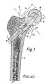
- Fig. 1 illustrates a hip joint prosthesis of the type disclosed in WO93/16663.
- the prosthesis comprises a cylindrical first fixture part 1, and a plug-like second fixture part 2 carrying a ball or caput 3.
- the first fixture part 1 is made in, several versions of different length, whereas the plug-like second fixture part 2 is made in several versions of different diameter.
- the first fixture part 1 has been fitted into a bore 4, which has been drilled longitudinally through the cancellous bone of the femoral collum 5 along a drill axis B-B by means of a drill tool (reference numeral 24 in Fig. 2) having a diameter corresponding to that of the: first fixture part 1.
- the plug-like, second fixture part 2 has been fitted into a cylindrical recess 6 cut in the cancellous bone of the collum 5 so as to be coaxial with the drilled bore 4.
- the cylindrical recess 6 has been. cut longitudinally along the drill axis B-B in a direction away from the head 8 by means of a rotary milling tool (not shown).
- the milling tool is available in several sizes, each corresponding to a specific diameter of a plug-like, second fixture part 2, and comprises an elongate guide element to be inserted in and guided by the drilled bore 4.
- the plug-like, second fixture part 2 is delimited by a circumferential flange 7 limiting the insertion into the recess 6, the flange 7 abutting against a cut end surface 11 which defines a cutting plane P, along which the head 8 of the collum 5 has been removed.
- WO93/ 16663 for further details of this prior-art prosthesis shown in Fig. 1 and the anchorage thereof.
- the orientation of the fixture parts 1 and 2 relative to the collum 5, and especially the cortical bone 10, differs from what has previously been disclosed in WO93/ 16663. More specifically, the plug-like, second fixture part 2 firmly engages, along its entire length, the cortical bone 10 in a specific area 12 located along the medial aspect of the transition zone between the femoral collum 5 and the femoral shaft 9. Since the overall object is to maximise the support for the fixture part 1, 2 without penetrating the cortical bone 10, the area 12 of the cortical bone 10, which is relatively thick as illustrated in Fig. 1, is advantageously used for engaging and supporting the plug-like, second fixture part 2.
- both the orientation and the position of the drill axis B-B are preferably established with a high degree of accuracy during the drilling operation, since the bore 4 is subsequently used as guide channel for the milling tool when cutting the recess 6 in the cancellous bone of the collum 5, as stated above.
- the cylindrical periphery of the cut recess 6 will either (i) be entirely or partly spaced from the advantageous area 12 of the cortical bone 10, resulting in no or only partial anchorage of the plug-like, second fixture part 2 in the cortical bone 10, especially in the advantageous area 12, or (ii) be displaced towards the cortical bone to such an extent that the latter is penetrated, either by the recess 6 or by the plug-like, second fixture part 2.
- a dashed line N indicates the narrowest part 13 of the collum 5. Due to the funnel-shape of the collum 5, correct positioning of the drill axis B-B relative to the collum 5, i.e. correct positioning of the point of intersection of the drill axis B-B and the cutting plane P, cannot be determined on the basis of the profile section of the cut end surface 11, since it is the size of the narrowest part 13 that determines the maximum permissible size of the milling tool to be used, and hence the maximum permissible diameter of the plug-like, second fixture part 2.
- the cutting plane P has been so chosen as to make a predetermined cutting angle ⁇ C with the femoral shaft 9, the longitudinal main direction of which is identified by a straight line A-A, and be located at a predetermined cutting level L C with respect to the end of the head 8.
- Resection of the head 8 along such a well-defined cutting plane may preferably be performed by means of a cutting guide instrument as disclosed in the above-mentioned SE 9501828-9.
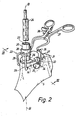
- the instrument according to the invention comprises a drill guide 20 having a base member 21 and a positioning member 22 connected to the drill guide 20.
- the drill guide 20 is in the form of a tubular cylinder, the inner periphery of which defines a guide channel 23 for receiving and guiding a drill tool 24 along the drill axis B-B.
- the drill tool 24 is a trephine, but any other drill tool may also be used.
- the base member 21 of the drill guide 20 is in the form of a plate having an plane abutment surface 25 covering essentially the entire cut end surface 11.
- One end 26 of the cylinder 20 is fixedly connected at right angles to the opposite surface 27 of the abutment plate 21, which is provided with a through hole (not shown) coinciding with the guide channel 23 of the cylinder 20.
- the positioning member 22 is an exchangeable part of the drill guide instrument and comprises a cylindrical connection sleeve 28, which fits loosely over the cylinder 20 and is provided with two essentially U-shaped positioning arms 29.
- the positioning arms 29 extend from the connection sleeve 28, beyond the base plate 21 and towards the collum 5, as shown in Figs 2 and 4.
- the U-shaped positioning arms 29 are essentially orthogonal and extend in respective radial planes of the drill axis B-B.
- the distal ends of the positioning arms 29 form abutment ends 30, both of which are to be brought into contact with the periphery of the collum 5 at the narrowest portion 13 thereof, as indicated by the dashed line N in Fig. 2.
- the preferred embodiment of the instrument comprises a set of exchangeable positioning members 22, each having a connection sleeve 28 with two positioning arms 29.
- the positioning members 22 of the set differ only in radial distance, as measured from their abutment ends 30 to the centre axis of the connection sleeve 28.
- the two abutment ends 30 and the centre axis of the connection sleeve 28 define circles of different diameters for each of the positioning members 22 of the set.
- such a set may comprise four different positioning members 22, corresponding to diameters of 16 mm, 17 mm, 18 mm and 19 mm.
- FIG. 5 illustrates a control device comprising a cylindrical shaft 31 and a stepped conical base 32 and adapted to verify that the abutment ends 30 of each positioning member 22 of such a four-member set are located at the correct distance from the centre axis of the connection sleeve 28.
- the diameter of the plug-like, second fixture part 2 should be selected to be 18 mm.
- the recess 6 for the plug-like fixture part 2 may be cut with a milling tool having a diameter of 18 mm or slightly less, depending on whether the plug-like, second fixture part 2 will remove any further bone tissue when inserted in the recess 6.
- the base plate 21 is clamped against the cut end surface 11 of the collum 5 by means of two pivotable jaws 33.
- each jaw is pivotably connected to the base plate 21 at 34 for pivotal movement in a plane perpendicular to the base plate 21.
- the jaws 33 comprise co-operating, toothed engagement ends 35, which can be clamped against the collum 5 by forcing apart the opposite ends 36 with the aid of a separate hand-held clamping tool 37 having conventional means 38 for locking the tool in a clamped position.
- the above-mentioned funnel shape of the collum 5 in combination with the pivotal movement of the jaws 33 will also effect clamping of the base plate 21 downwards in Fig. 3 against the cut end surface 11, in order to ensure correct orientation of the cylinder 21 relative to the cutting plane P.
- the following steps are to be taken when using the above drill guide instrument.
- the size of the narrowest portion 13 of the collum 5 is measured.
- the position of the narrowest portion 13 may be marked by a line (N).
- a positioning member 22 corresponding to a convenient size of the plug-like, second fixture part 2 is selected for mounting on the cylinder 20.
- the abutment surface 25 of the base plate 21 is brought into engagement with the cut end surface 11 of the collum 5.
- the positioning member is manually displaced along the cylinder 20 from the base plate 21, as illustrated in Fig. 4, to a position in which the abutment ends 30 of the positioning arms 29 are on a level (at line N) with the narrowest portion 13.
- the indication line can be dispensed with, since the narrowest portion 13 of the collum may easily be located by displacing the positioning member 22 along the cylinder 20 while constantly urging the two abutment ends 30 into contact with the periphery of the collum.
- the connection sleeve 28 is rotated about the cylinder 20 to an angular position in which the abutment ends 30 of the arms 39 are at equal angular distance from a plane of symmetry of the collum, as indicated by a dashed line L in Fig. 2.
- the drill axis B-B being now correctly orientated and positioned, the whole instrument is temporarily fixed to the collum 5 by means of the jaws 33 and the clamping tool 37.
- the drill tool 24 can now be received in and guided by the drill channel 23 for drilling the bore 4 longitudinally through the collum 5, whereupon the drill guide instrument is removed. Finally, the recess 6 is cut in the cancellous bone as described above, using the drilled bore 4 as guide channel for a milling tool.
- the drill guide may be formed by a number of coaxial rings forming a guide channel for a drill tool.
- the drill tool may be formed integral with the instrument, and in that case the structure of the drill guide may differ essentially from that of the embodiment shown in the Figures.
- the positioning member may be fixedly connected to the drill guide.
- the base member other alternatives than a plate could be envisaged, e.g. some form of tripod arrangement for orienting the drill guide relative to the cut end surface.
- the abutment ends 30 of the positioning member could be in the form of a continuous ring abutting against the collum along the line N.
Landscapes
- Health & Medical Sciences (AREA)
- Surgery (AREA)
- Life Sciences & Earth Sciences (AREA)
- Animal Behavior & Ethology (AREA)
- Public Health (AREA)
- Orthopedic Medicine & Surgery (AREA)
- Oral & Maxillofacial Surgery (AREA)
- Engineering & Computer Science (AREA)
- Biomedical Technology (AREA)
- Heart & Thoracic Surgery (AREA)
- Medical Informatics (AREA)
- Molecular Biology (AREA)
- Dentistry (AREA)
- General Health & Medical Sciences (AREA)
- Nuclear Medicine, Radiotherapy & Molecular Imaging (AREA)
- Veterinary Medicine (AREA)
- Surgical Instruments (AREA)
- Prostheses (AREA)
- Paper (AREA)
- Perforating, Stamping-Out Or Severing By Means Other Than Cutting (AREA)
- Drilling And Boring (AREA)
- Drilling Tools (AREA)
- Earth Drilling (AREA)
- Forklifts And Lifting Vehicles (AREA)
- Solid-Sorbent Or Filter-Aiding Compositions (AREA)
- Inorganic Fibers (AREA)
- Catalysts (AREA)
Claims (11)
- Bohrlehre zur Führung eines Bohrwerkzeugs (24) beim Bohren eines längsgerichteten Loches (4) durch das Collum femoris (5) eines menschlichen Oberschenkelknochens (9) nach einer Resektion des Kopfes (8) des Oberschenkelhalses (5) in einer Schnittebene (P), enthaltend
eine Bohrführung (20) mit einem Basisteil (21) und dazu eingerichtet, das Bohrwerkzeug (24) entlang einer Bohrachse (B-B) gegenüber dem Basisteil (21) zu führen, wobei das Basisteil (21) derart ausgebildet ist, dass es in einer Position gegen eine Schnittendfläche (11) des Collum (5) anliegt, welche eine Schnittebene (P) zur Erzielung einer vorher festgelegten Orientierung der Bohrachse (B-B) bezüglich der Schnittebene (P) definiert, und
ein Positionierelement (22), das sich von der Bohrführung (20) erstreckt und dazu eingerichtet ist, mit dem Umfang des engsten Bereiches (13) des Collum (5) an mindestens zwei umfangsmässig im Abstand befindlichen Kontaktstellen (30) verbunden zu werden, wenn das Basisteil in der genannten Position an der genannten Schnittendfläche anliegt, derart, dass sich die Bohrachse (B-B) in der geringsten Entfernung vom Umfang des genannten engsten Bereiches (13) des Collum (5) befindet. - Bohrlehre nach Anspruch 1, bei der das genannte Positionierelement (22) abnehmbar mit dem Gerät verbunden ist, derart, dass es durch andere Positionierelemente (22) ersetzt werden kann, welche anderen Werten der genannten geringsten Entfernung entsprechen.
- Bohrlehre nach einem der vorstehenden Ansprüche, bei der die Bohrführung (20) mit einem Bohrkanal (23) zur Aufnahme und Führung des Bohrwerkzeuges (24) entlang der Bohrachse (B-B) versehen ist.
- Bohrlehre nach einem der vorstehenden Ansprüche, bei der das Positionierelement (22) gegenüber dem Basisteil (21) quer zur Schnittebene (P) verschiebbar ist.
- Bohrlehre nach Anspruch 4, sofern dieser vom Anspruch 3 abhängt, worin die Bohrführung (20) ein rohrförmiges Element (20) enthält, welches an einem Ende (26) mit dem Basisteil (21) verbunden ist und eine inneren zylindrische Oberfläche aufweist, welche den Bohrkanal (23) definiert, sowie eine äussere zylindrische Fläche entlang welcher eine Verbindungshülse (28) des Positionierelementes (22) verschiebbar ist.
- Bohrlehre nach einem der vorstehenden Ansprüche, bei der das Positionierelement (22) um die Bohrachse (B-B) drehbar ist.
- Bohrlehre nach einem der vorstehenden Ansprüche, bei der das Basisteil (21) eine ebene Anlagefläche (25) aufweist, die ausreichend dimensioniert ist, um mindestens den grössten Teil der Schnittendfläche (11) des Knochenhalses (5), welche die Schnittebene (P) defindert, zu bedecken.
- Bohrlehre nach einem der vorstehenden Ansprüche, bei der die Bohrachse (B-B) rechtwinklig zum Basisteil (21) orientiert ist.
- Bohrlehre nach einem der vorstehenden Ansprüche, weiterhin mit Mitteln (33, 37) zur Befestigung de Basisteiles (21) am Knochenhals (5) versehen.
- Bohrlehre nach Anspruch 9, bei der die Befestigungsmittel (33, 37) mindestens zwei Backen (33) enthalten, die scharnierartig mit dem Basisteil (21) verbunden sind und quer zur Schnittebene (P) schwenkbar sind, damit sie am äusseren Umfang des Knochenhalses (5) angeklemmt werden können.
- Bohrlehre nach Anspruch 10, bei der die Backen (33) am Basisteil (21) derart angelenkt sind, dass sie das Basisteil (21) gegen die Schnittendfläche (11) des Knochenhalses (5) anpressen, wenn sie am Knochenhals (5) angeklemmt sind.
Applications Claiming Priority (3)
| Application Number | Priority Date | Filing Date | Title |
|---|---|---|---|
| SE9501829A SE9501829D0 (sv) | 1995-05-17 | 1995-05-17 | Drill guide |
| SE9501829 | 1995-05-17 | ||
| PCT/SE1996/000490 WO1996036285A1 (en) | 1995-05-17 | 1996-04-17 | Drill guide instrument |
Publications (2)
| Publication Number | Publication Date |
|---|---|
| EP0957782A1 EP0957782A1 (de) | 1999-11-24 |
| EP0957782B1 true EP0957782B1 (de) | 2004-01-14 |
Family
ID=20398341
Family Applications (1)
| Application Number | Title | Priority Date | Filing Date |
|---|---|---|---|
| EP96914486A Expired - Lifetime EP0957782B1 (de) | 1995-05-17 | 1996-04-17 | Bohrlehre instrument |
Country Status (23)
| Country | Link |
|---|---|
| US (1) | US5817098A (de) |
| EP (1) | EP0957782B1 (de) |
| JP (1) | JP3307399B2 (de) |
| KR (1) | KR100267823B1 (de) |
| CN (1) | CN1119124C (de) |
| AT (1) | ATE257672T1 (de) |
| AU (1) | AU693697B2 (de) |
| BR (1) | BR9608821A (de) |
| CA (1) | CA2219116C (de) |
| CZ (1) | CZ288799B6 (de) |
| DE (1) | DE69631344T2 (de) |
| DK (1) | DK0957782T3 (de) |
| ES (1) | ES2213773T3 (de) |
| HU (1) | HU220351B (de) |
| IS (1) | IS4613A (de) |
| NO (1) | NO975173D0 (de) |
| NZ (1) | NZ308248A (de) |
| PL (1) | PL183613B1 (de) |
| PT (1) | PT957782E (de) |
| RU (1) | RU2157665C2 (de) |
| SE (1) | SE9501829D0 (de) |
| TR (1) | TR199701374T1 (de) |
| WO (1) | WO1996036285A1 (de) |
Families Citing this family (57)
| Publication number | Priority date | Publication date | Assignee | Title |
|---|---|---|---|---|
| US6022357A (en) * | 1997-03-03 | 2000-02-08 | Aesculap Ag & Co. Kg | Surgical instrument |
| US6342057B1 (en) | 2000-04-28 | 2002-01-29 | Synthes (Usa) | Remotely aligned surgical drill guide |
| US6379364B1 (en) | 2000-04-28 | 2002-04-30 | Synthes (Usa) | Dual drill guide for a locking bone plate |
| EP1252868B1 (de) * | 2001-04-27 | 2006-06-21 | Zimmer GmbH | Bohrlehere für die Festlegung der Achse einer Femurkopfprothese |
| KR100407894B1 (ko) * | 2001-09-07 | 2003-12-01 | 한국과학기술원 | 고관절 전치환술용 게이지장치 |
| GB0127658D0 (en) * | 2001-11-19 | 2002-01-09 | Acrobot Company The Ltd | Apparatus for surgical instrument location |
| US7247171B2 (en) * | 2002-03-11 | 2007-07-24 | Sotereanos Nicholas G | Modular hip implants |
| ZA200601086B (en) * | 2003-08-01 | 2007-05-30 | Synthes Gmbh | Drill guide assembly for a bone fixation device |
| GB0322084D0 (en) * | 2003-09-22 | 2003-10-22 | Depuy Int Ltd | A drill guide assembly |
| US7131974B2 (en) * | 2003-10-14 | 2006-11-07 | Keyer Thomas R | Surgical drill guide |
| AU2004292996B2 (en) * | 2003-11-20 | 2008-09-25 | Microport Orthopedics Holdings Inc. | Guide clamp for guiding placement of a guide wire in a femur |
| US8080014B2 (en) * | 2004-12-15 | 2011-12-20 | Koninklijke Philips Electronics N.V. | System and method for hyoidplasty |
| US7447565B2 (en) * | 2004-05-06 | 2008-11-04 | John Cerwin | Electronic alignment system |
| GB0411487D0 (en) * | 2004-05-22 | 2004-06-23 | Depuy Int Ltd | Surgical jig |
| GB0505782D0 (en) * | 2005-03-22 | 2005-04-27 | Depuy Int Ltd | Surgical guide |
| US20070005067A1 (en) * | 2005-06-21 | 2007-01-04 | Brian Dross | Arthoscopic method and apparatus for tissue attachment to bone |
| CN101277651B (zh) * | 2005-08-31 | 2010-08-25 | 齐默有限公司 | 移植器 |
| EP1772106A1 (de) * | 2005-10-06 | 2007-04-11 | Zimmer GmbH | Instrument zum Vorbereiten und/oder Bearbeiten eines Femurkopfes |
| US7371260B2 (en) * | 2005-10-26 | 2008-05-13 | Biomet Sports Medicine, Inc. | Method and instrumentation for the preparation and transplantation of osteochondral allografts |
| WO2007054553A1 (de) * | 2005-11-09 | 2007-05-18 | Zimmer Gmbh | Implantat |
| US20090048679A1 (en) * | 2006-02-09 | 2009-02-19 | Zimmer Gmbh | Implant |
| US8221423B2 (en) * | 2006-03-28 | 2012-07-17 | Warsaw Orthopedic, Inc. | Osteochondral plug graft harvesting instrument and kit |
| WO2007125060A1 (de) * | 2006-04-28 | 2007-11-08 | Zimmer Gmbh | Implantat |
| US20070276506A1 (en) * | 2006-05-25 | 2007-11-29 | Biomet Manufacturing Corp. | Demineralized osteochondral plug |
| RU2353322C2 (ru) * | 2006-06-13 | 2009-04-27 | Алексей Владимирович Салаев | Устройство для формирования канала в кости и установки в него винта шанца |
| US7985230B2 (en) * | 2006-07-27 | 2011-07-26 | Warsaw Orthopedic, Inc. | System and method of harvesting osteochondral plugs |
| AU2007281000A1 (en) * | 2006-08-03 | 2008-02-07 | Orthosoft Inc. | Computer-assisted surgery tools and system |
| CA2671523C (en) | 2006-12-07 | 2013-02-12 | Anatol Podolsky | Method and apparatus for total hip replacement |
| US8974540B2 (en) | 2006-12-07 | 2015-03-10 | Ihip Surgical, Llc | Method and apparatus for attachment in a modular hip replacement or fracture fixation device |
| US8579985B2 (en) | 2006-12-07 | 2013-11-12 | Ihip Surgical, Llc | Method and apparatus for hip replacement |
| WO2008076559A1 (en) * | 2006-12-15 | 2008-06-26 | Synthes Usa, Llc | Osteotomy guide and method of cutting the medial distal tibia employing the same |
| GB0703691D0 (en) * | 2007-02-26 | 2007-04-04 | Benoist Girard Sas | Apparatus for Preparing A Prosthetic Stem Cavity in A Femur |
| GB0712247D0 (en) * | 2007-06-25 | 2007-08-01 | I J Smith & Nephew Ltd | Medical device |
| EP2187844A2 (de) * | 2007-07-31 | 2010-05-26 | Zimmer, Inc. | Prothetische gelenkspalt-interpositionsvorrichtung mit inneren anlageflächen |
| US8322256B2 (en) * | 2007-10-05 | 2012-12-04 | Biomet Manufacturing Corp. | System for forming a tendon-bone graft |
| US8303592B2 (en) * | 2007-10-05 | 2012-11-06 | Biomet Manufacturing Corp. | System for forming a tendon-bone graft |
| WO2009061792A2 (en) * | 2007-11-05 | 2009-05-14 | Stefan Kreuzer | Apparatus and method for aligning a guide pin for joint re-surfacing |
| CN104352268A (zh) | 2008-01-14 | 2015-02-18 | 康文图斯整形外科公司 | 用于骨折修补的装置和方法 |
| WO2010028811A1 (en) * | 2008-09-10 | 2010-03-18 | Nobel Biocare Services Ag | Device and procedure for implanting a dental implant |
| GB0822078D0 (en) * | 2008-12-03 | 2009-01-07 | Finsbury Dev Ltd | Tool |
| EP2523614A4 (de) | 2010-01-15 | 2017-02-15 | Conventus Orthopaedics, Inc. | Drehbare und starre orthopädische stange |
| AU2011207550B2 (en) * | 2010-01-20 | 2016-03-10 | Conventus Orthopaedics, Inc. | Apparatus and methods for bone access and cavity preparation |
| US8906022B2 (en) | 2010-03-08 | 2014-12-09 | Conventus Orthopaedics, Inc. | Apparatus and methods for securing a bone implant |
| EP2389905B1 (de) * | 2010-05-24 | 2012-05-23 | Episurf Medical AB | Methode zur Gestaltung eines OP-Kits zur Knorpelreparatur in einem Gelenk |
| TWI503098B (zh) * | 2011-01-31 | 2015-10-11 | Surgical clamps | |
| EP2836136A4 (de) * | 2012-04-04 | 2016-04-20 | Smith & Nephew Inc | Chirurgische führung mit intraoperativem tiefenfeedback |
| CN105939677A (zh) | 2013-12-12 | 2016-09-14 | 康文图斯整形外科公司 | 组织移位工具和方法 |
| US20150313640A1 (en) * | 2014-04-30 | 2015-11-05 | Andres Eduardo O'DALY | Surgical instrument with movable guide and sleeve |
| US10543004B2 (en) * | 2015-12-23 | 2020-01-28 | Osteomed Llc | Bone centering drill guide |
| CN105943138B (zh) * | 2016-05-18 | 2018-11-23 | 南京大学医学院附属鼓楼医院 | 医用肱骨外科颈骨折肱骨头复位固定器 |
| CN106388905B (zh) * | 2016-09-14 | 2019-08-16 | 合肥市第二人民医院 | 一种可定位钻孔的骨折复位钳 |
| US10631881B2 (en) | 2017-03-09 | 2020-04-28 | Flower Orthopedics Corporation | Plating depth gauge and countersink instrument |
| US10918426B2 (en) | 2017-07-04 | 2021-02-16 | Conventus Orthopaedics, Inc. | Apparatus and methods for treatment of a bone |
| US10758280B2 (en) | 2017-10-09 | 2020-09-01 | Acumed Llc | System and method for bone fixation using a nail locked to an encircling anchor |
| CN110313971B (zh) * | 2018-03-29 | 2024-05-07 | 林克骨科(中国)有限公司 | 导引式角度钻 |
| JP7325967B2 (ja) * | 2019-01-17 | 2023-08-15 | 京セラ株式会社 | 手術器具 |
| US20210228221A1 (en) * | 2020-01-23 | 2021-07-29 | Arthrex, Inc. | Self-positioning drill guide |
Family Cites Families (11)
| Publication number | Priority date | Publication date | Assignee | Title |
|---|---|---|---|---|
| US4467801A (en) | 1983-03-09 | 1984-08-28 | Wright Manufacturing Company | Method and apparatus for shaping a proximal tibial surface |
| DE3332642A1 (de) * | 1983-09-09 | 1985-04-04 | Ortopedia Gmbh, 2300 Kiel | Vorrichtung zum auffinden von querbohrungen intramedullaerer implantate |
| US4528980A (en) * | 1983-10-19 | 1985-07-16 | Howmedica, Inc. | Acetabulum sizer and drill guide |
| SE442083B (sv) * | 1984-03-14 | 1985-12-02 | Magnus Odensten | Anordning for inriktning och styrning av en fram och ater forskjutbar borrstang for borrning av ett genomgaende hal i atminstone den ena av tva en kneled bildande sken- och larben |
| US4736737A (en) * | 1986-03-31 | 1988-04-12 | William Fargie | Tibial cutting jig |
| US4722330A (en) * | 1986-04-22 | 1988-02-02 | Dow Corning Wright Corporation | Femoral surface shaping guide for knee implants |
| SE463072B (sv) * | 1988-06-10 | 1990-10-08 | Bjoern Albrektsson | Hoeftledsprotes |
| SU1644933A1 (ru) * | 1989-04-21 | 1991-04-30 | Крымский Медицинский Институт | Направитель фиксатора дл остеосинтеза шейки бедра |
| SE9102216D0 (sv) * | 1991-07-23 | 1991-07-23 | Astra Ab | Hip joint prosthesis |
| SE9200597D0 (sv) * | 1992-02-28 | 1992-02-28 | Astra Ab | Hip joint prosthesis ii |
| US5417695A (en) | 1992-07-27 | 1995-05-23 | Pfizer Hospital Products Group, Inc. | Instrumentation for preparing a distal femur |
-
1995
- 1995-05-17 SE SE9501829A patent/SE9501829D0/xx unknown
-
1996
- 1996-04-17 HU HU9900303A patent/HU220351B/hu not_active IP Right Cessation
- 1996-04-17 CZ CZ19973623A patent/CZ288799B6/cs not_active IP Right Cessation
- 1996-04-17 BR BR9608821A patent/BR9608821A/pt not_active IP Right Cessation
- 1996-04-17 TR TR97/01374T patent/TR199701374T1/xx unknown
- 1996-04-17 CA CA002219116A patent/CA2219116C/en not_active Expired - Fee Related
- 1996-04-17 US US08/669,474 patent/US5817098A/en not_active Expired - Fee Related
- 1996-04-17 CN CN96193970A patent/CN1119124C/zh not_active Expired - Fee Related
- 1996-04-17 WO PCT/SE1996/000490 patent/WO1996036285A1/en not_active Ceased
- 1996-04-17 KR KR1019970708178A patent/KR100267823B1/ko not_active Expired - Fee Related
- 1996-04-17 RU RU97120514/14A patent/RU2157665C2/ru not_active IP Right Cessation
- 1996-04-17 JP JP53473796A patent/JP3307399B2/ja not_active Expired - Fee Related
- 1996-04-17 DK DK96914486T patent/DK0957782T3/da active
- 1996-04-17 PL PL96323351A patent/PL183613B1/pl not_active IP Right Cessation
- 1996-04-17 AU AU57831/96A patent/AU693697B2/en not_active Ceased
- 1996-04-17 ES ES96914486T patent/ES2213773T3/es not_active Expired - Lifetime
- 1996-04-17 NZ NZ308248A patent/NZ308248A/en unknown
- 1996-04-17 DE DE69631344T patent/DE69631344T2/de not_active Expired - Fee Related
- 1996-04-17 EP EP96914486A patent/EP0957782B1/de not_active Expired - Lifetime
- 1996-04-17 PT PT96914486T patent/PT957782E/pt unknown
- 1996-04-17 AT AT96914486T patent/ATE257672T1/de not_active IP Right Cessation
-
1997
- 1997-11-11 NO NO975173A patent/NO975173D0/no not_active Application Discontinuation
- 1997-11-14 IS IS4613A patent/IS4613A/is unknown
Also Published As
Similar Documents
| Publication | Publication Date | Title |
|---|---|---|
| EP0957782B1 (de) | Bohrlehre instrument | |
| EP0828456B1 (de) | Führungsinstrument zum schneiden | |
| JP3180223B2 (ja) | 髄内爪部材中において骨用ネジを機械的に心合わせするための装置 | |
| EP1205151B1 (de) | Zielgerät für transfemorale Osteotomie | |
| US6277121B1 (en) | Patella reaming system | |
| CA2203581A1 (en) | Mechanical system for blind nail-hole alignment of bone screws | |
| WO2002026145A1 (en) | Guiding instrument for the resection of a femoral neck | |
| AU779574B2 (en) | Targeting apparatus for use in performing endofemoral osteotomy surgery | |
| AU2008200892B2 (en) | Apparatus for indicating the bone thickness between a cavity in a bone and the bone surface | |
| EP1205149A2 (de) | Zielgerät zur Resektion des Femurs für transfemorale Osteotomie | |
| JP4634115B2 (ja) | 肩関節形成術中に上腕骨構成要素を位置決めするための方法および器具 | |
| MXPA97008593A (en) | Instrument guide of perforac | |
| AU705390C (en) | Cutting guide instrument | |
| CA2138473C (en) | Medullary cavity template |
Legal Events
| Date | Code | Title | Description |
|---|---|---|---|
| PUAI | Public reference made under article 153(3) epc to a published international application that has entered the european phase |
Free format text: ORIGINAL CODE: 0009012 |
|
| 17P | Request for examination filed |
Effective date: 19971217 |
|
| AK | Designated contracting states |
Kind code of ref document: A1 Designated state(s): AT BE CH DE DK ES FI FR GB GR IE IT LI NL PT SE |
|
| RAP1 | Party data changed (applicant data changed or rights of an application transferred) |
Owner name: ASTRAZENECA AB |
|
| RAP1 | Party data changed (applicant data changed or rights of an application transferred) |
Owner name: ASTRA TECH AB |
|
| 17Q | First examination report despatched |
Effective date: 20020925 |
|
| GRAP | Despatch of communication of intention to grant a patent |
Free format text: ORIGINAL CODE: EPIDOSNIGR1 |
|
| GRAS | Grant fee paid |
Free format text: ORIGINAL CODE: EPIDOSNIGR3 |
|
| GRAA | (expected) grant |
Free format text: ORIGINAL CODE: 0009210 |
|
| AK | Designated contracting states |
Kind code of ref document: B1 Designated state(s): AT BE CH DE DK ES FI FR GB GR IE IT LI NL PT SE |
|
| REG | Reference to a national code |
Ref country code: GB Ref legal event code: FG4D |
|
| REG | Reference to a national code |
Ref country code: CH Ref legal event code: EP |
|
| REG | Reference to a national code |
Ref country code: IE Ref legal event code: FG4D |
|
| REF | Corresponds to: |
Ref document number: 69631344 Country of ref document: DE Date of ref document: 20040219 Kind code of ref document: P |
|
| PGFP | Annual fee paid to national office [announced via postgrant information from national office to epo] |
Ref country code: FI Payment date: 20040405 Year of fee payment: 9 |
|
| REG | Reference to a national code |
Ref country code: GR Ref legal event code: EP Ref document number: 20040400970 Country of ref document: GR |
|
| REG | Reference to a national code |
Ref country code: SE Ref legal event code: TRGR |
|
| REG | Reference to a national code |
Ref country code: CH Ref legal event code: NV Representative=s name: BUGNION S.A. |
|
| REG | Reference to a national code |
Ref country code: DK Ref legal event code: T3 |
|
| REG | Reference to a national code |
Ref country code: PT Ref legal event code: SC4A Free format text: AVAILABILITY OF NATIONAL TRANSLATION Effective date: 20040413 |
|
| REG | Reference to a national code |
Ref country code: ES Ref legal event code: FG2A Ref document number: 2213773 Country of ref document: ES Kind code of ref document: T3 |
|
| ET | Fr: translation filed | ||
| PLBE | No opposition filed within time limit |
Free format text: ORIGINAL CODE: 0009261 |
|
| STAA | Information on the status of an ep patent application or granted ep patent |
Free format text: STATUS: NO OPPOSITION FILED WITHIN TIME LIMIT |
|
| 26N | No opposition filed |
Effective date: 20041015 |
|
| PG25 | Lapsed in a contracting state [announced via postgrant information from national office to epo] |
Ref country code: FI Free format text: LAPSE BECAUSE OF NON-PAYMENT OF DUE FEES Effective date: 20050417 |
|
| PGFP | Annual fee paid to national office [announced via postgrant information from national office to epo] |
Ref country code: IE Payment date: 20090331 Year of fee payment: 14 |
|
| PGFP | Annual fee paid to national office [announced via postgrant information from national office to epo] |
Ref country code: ES Payment date: 20090407 Year of fee payment: 14 Ref country code: DK Payment date: 20090407 Year of fee payment: 14 |
|
| PGFP | Annual fee paid to national office [announced via postgrant information from national office to epo] |
Ref country code: SE Payment date: 20090416 Year of fee payment: 14 Ref country code: NL Payment date: 20090406 Year of fee payment: 14 Ref country code: IT Payment date: 20090423 Year of fee payment: 14 Ref country code: FR Payment date: 20090403 Year of fee payment: 14 Ref country code: DE Payment date: 20090403 Year of fee payment: 14 Ref country code: AT Payment date: 20090406 Year of fee payment: 14 |
|
| PGFP | Annual fee paid to national office [announced via postgrant information from national office to epo] |
Ref country code: BE Payment date: 20090406 Year of fee payment: 14 |
|
| PGFP | Annual fee paid to national office [announced via postgrant information from national office to epo] |
Ref country code: CH Payment date: 20090406 Year of fee payment: 14 |
|
| PGFP | Annual fee paid to national office [announced via postgrant information from national office to epo] |
Ref country code: GR Payment date: 20090410 Year of fee payment: 14 Ref country code: GB Payment date: 20090403 Year of fee payment: 14 |
|
| BERE | Be: lapsed |
Owner name: *ASTRA TECH A.B. Effective date: 20100430 |
|
| REG | Reference to a national code |
Ref country code: NL Ref legal event code: V1 Effective date: 20101101 |
|
| EUG | Se: european patent has lapsed | ||
| REG | Reference to a national code |
Ref country code: CH Ref legal event code: PL |
|
| REG | Reference to a national code |
Ref country code: DK Ref legal event code: EBP |
|
| GBPC | Gb: european patent ceased through non-payment of renewal fee |
Effective date: 20100417 |
|
| REG | Reference to a national code |
Ref country code: IE Ref legal event code: MM4A |
|
| REG | Reference to a national code |
Ref country code: FR Ref legal event code: ST Effective date: 20101230 |
|
| PG25 | Lapsed in a contracting state [announced via postgrant information from national office to epo] |
Ref country code: NL Free format text: LAPSE BECAUSE OF NON-PAYMENT OF DUE FEES Effective date: 20101101 Ref country code: IE Free format text: LAPSE BECAUSE OF NON-PAYMENT OF DUE FEES Effective date: 20100419 Ref country code: AT Free format text: LAPSE BECAUSE OF NON-PAYMENT OF DUE FEES Effective date: 20100417 |
|
| PG25 | Lapsed in a contracting state [announced via postgrant information from national office to epo] |
Ref country code: PT Free format text: LAPSE BECAUSE OF NON-PAYMENT OF DUE FEES Effective date: 20101018 Ref country code: LI Free format text: LAPSE BECAUSE OF NON-PAYMENT OF DUE FEES Effective date: 20100430 Ref country code: DE Free format text: LAPSE BECAUSE OF NON-PAYMENT OF DUE FEES Effective date: 20101103 Ref country code: CH Free format text: LAPSE BECAUSE OF NON-PAYMENT OF DUE FEES Effective date: 20100430 |
|
| PG25 | Lapsed in a contracting state [announced via postgrant information from national office to epo] |
Ref country code: GR Free format text: LAPSE BECAUSE OF NON-PAYMENT OF DUE FEES Effective date: 20101103 Ref country code: BE Free format text: LAPSE BECAUSE OF NON-PAYMENT OF DUE FEES Effective date: 20100430 Ref country code: GB Free format text: LAPSE BECAUSE OF NON-PAYMENT OF DUE FEES Effective date: 20100417 Ref country code: IT Free format text: LAPSE BECAUSE OF NON-PAYMENT OF DUE FEES Effective date: 20100417 |
|
| PG25 | Lapsed in a contracting state [announced via postgrant information from national office to epo] |
Ref country code: DK Free format text: LAPSE BECAUSE OF NON-PAYMENT OF DUE FEES Effective date: 20100503 |
|
| REG | Reference to a national code |
Ref country code: ES Ref legal event code: FD2A Effective date: 20110715 |
|
| PG25 | Lapsed in a contracting state [announced via postgrant information from national office to epo] |
Ref country code: ES Free format text: LAPSE BECAUSE OF NON-PAYMENT OF DUE FEES Effective date: 20110705 |
|
| PG25 | Lapsed in a contracting state [announced via postgrant information from national office to epo] |
Ref country code: ES Free format text: LAPSE BECAUSE OF NON-PAYMENT OF DUE FEES Effective date: 20100418 |
|
| PG25 | Lapsed in a contracting state [announced via postgrant information from national office to epo] |
Ref country code: FR Free format text: LAPSE BECAUSE OF NON-PAYMENT OF DUE FEES Effective date: 20100430 |
|
| PG25 | Lapsed in a contracting state [announced via postgrant information from national office to epo] |
Ref country code: PT Free format text: LAPSE BECAUSE OF NON-PAYMENT OF DUE FEES Effective date: 20101027 Ref country code: SE Free format text: LAPSE BECAUSE OF NON-PAYMENT OF DUE FEES Effective date: 20100418 |
|
| PGFP | Annual fee paid to national office [announced via postgrant information from national office to epo] |
Ref country code: PT Payment date: 20090417 Year of fee payment: 14 |