EP0953947A2 - Selbstbedienungsendgerät - Google Patents
Selbstbedienungsendgerät Download PDFInfo
- Publication number
- EP0953947A2 EP0953947A2 EP99303209A EP99303209A EP0953947A2 EP 0953947 A2 EP0953947 A2 EP 0953947A2 EP 99303209 A EP99303209 A EP 99303209A EP 99303209 A EP99303209 A EP 99303209A EP 0953947 A2 EP0953947 A2 EP 0953947A2
- Authority
- EP
- European Patent Office
- Prior art keywords
- peripheral
- terminal
- control application
- terminal according
- signal
- Prior art date
- Legal status (The legal status is an assumption and is not a legal conclusion. Google has not performed a legal analysis and makes no representation as to the accuracy of the status listed.)
- Withdrawn
Links
Images

Classifications
-
- G—PHYSICS
- G06—COMPUTING OR CALCULATING; COUNTING
- G06Q—INFORMATION AND COMMUNICATION TECHNOLOGY [ICT] SPECIALLY ADAPTED FOR ADMINISTRATIVE, COMMERCIAL, FINANCIAL, MANAGERIAL OR SUPERVISORY PURPOSES; SYSTEMS OR METHODS SPECIALLY ADAPTED FOR ADMINISTRATIVE, COMMERCIAL, FINANCIAL, MANAGERIAL OR SUPERVISORY PURPOSES, NOT OTHERWISE PROVIDED FOR
- G06Q20/00—Payment architectures, schemes or protocols
- G06Q20/08—Payment architectures
- G06Q20/18—Payment architectures involving self-service terminals [SST], vending machines, kiosks or multimedia terminals
-
- G—PHYSICS
- G07—CHECKING-DEVICES
- G07F—COIN-FREED OR LIKE APPARATUS
- G07F19/00—Complete banking systems; Coded card-freed arrangements adapted for dispensing or receiving monies or the like and posting such transactions to existing accounts, e.g. automatic teller machines
- G07F19/20—Automatic teller machines [ATMs]
- G07F19/211—Software architecture within ATMs or in relation to the ATM network
Definitions
- This invention relates to a self service terminal (SST) and to a network of SSTs.
- the invention relates to a transaction terminal, such as a banking or retail transaction terminal, and to a network of such terminals.
- a typical transaction terminal may be an automated teller machine (ATM), a retail point-of-sale (PoS) terminal, a financial services centre (FSC), or a transaction kiosk.
- Each terminal has a central processor, typically PC based, which controls the operation of the terminal.
- the application software for controlling the terminal operation is stored on a mass storage device within the terminal such as a hard disk.
- a transaction terminal is connected by a communication link to a server containing (or being able to access) an information database (termed a legacy Host).
- a plurality of terminals which may be of the same or of a different kind; are connected to the server in a transaction network.
- Simple client-server transactions are conducted between the terminal and the server to obtain specific customer information used in the processing of the customer's transaction.
- a banking terminal such as an ATM
- the transaction may typically be a cash withdrawal or a balance request.
- a retail terminal such as a PoS terminal
- a typical transaction is a price lookup.
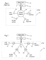
- Fig 1 is a block diagram of an ATM 10 (indicated by a dotted line) connected to a legacy host 12 via a server 14, the ATM 10 having a card reader 16, a receipt printer 18, a cash dispenser 20, and a user interface 22 (including an encrypting keyboard and a display).
- a server 14 the ATM 10 having a card reader 16, a receipt printer 18, a cash dispenser 20, and a user interface 22 (including an encrypting keyboard and a display).
- These devices must be provided with appropriate control software, and also require some form of embedded processing capability to conduct communications with a central processor and to implement commands received therefrom.
- All application software, peripheral device drivers and user interface files are held in a mass storage device in the ATM 10.
- these applications, drivers, and files form a large, monolithic central program 24 which is used to control all aspects of the operation of the ATM 10.
- This central program 24 runs on a central processor and performs a number of functions; for example, determining what graphics are presented to the customer on the display, retrieving encrypted PIN information from the card reader and passing it to the encrypting keyboard for validation, checking that the customer's account has sufficient funds if a cash withdrawal is requested, and such like.
- This central program 24 also includes the necessary business logic (which integrates and manages the different functions of the terminal) and error handling routines (which minimise the possibility of the terminal having to go out of service due to a malfunction). Therefore, design of this central program 24 is very complex and time consuming. In addition, updating device drivers or application software associated with a peripheral device is complicated because of the size of the central program 24.
- peripheral devices hereinafter referred to a peripherals
- application development tools are available that allow a developer to consider peripheral devices (hereinafter referred to a peripherals) as functional components, but it is still necessary to provide business logic and error handling facilities for these components within a single central program.
- This object is achieved generally by removing control of the terminal from one central program and providing each peripheral with its own dedicated program for controlling that peripheral.
- Each peripheral operates on a peer to peer basis and each peripheral has a common application flow so that the peripherals are not controlled by one central program but operate and interact as a team.
- the term application flow relates to the sequence of possible events within a terminal.
- a self service terminal comprises a plurality of peripheral devices characterised in that each device has an independent control application, the control applications being operable to communicate with each other; whereby, in use, a peripheral operates in response to a signal generated by another peripheral.
- peripheral-specific control applications operate and interact as a team so that there is no requirement for a central program to manage the peripherals and instruct them to operate.
- Another advantage of the invention is that the control application for each peripheral can be updated easily as it does not form part of a large central program.
- a peripheral device for use in a self service terminal having a plurality of such devices, characterised in that the device has an independent control application which is operable to communicate the internal states of the device to other devices in the terminal and to operate in response to signals communicated from control applications of other devices.
- control applications communicate with each other using a process to process communication protocol, such as TCP/IP, thereby allowing one process (one control application) to communicate with another process (another control application) whether both processes (control applications) are running on the same processor or not.
- a process to process communication protocol such as TCP/IP
- the control applications may communicate with each other using broadcast signals, whereby a peripheral communicates to all other peripherals within the terminal its present state.
- the control applications may communicate with each other using signals addressed directly to selected peripherals so that a peripheral communicates with those peripherals whose operation depends on or is connected with the state of that peripheral.
- a control application which operates in response to a signal communicated from another peripheral acknowledges receipt of that signal.
- This may be implemented by a protocol used for communications between peripherals, that is, the acknowledgement may be inherent in the protocol used.
- each control application is operable to identify any peripheral which does not acknowledge receipt of a signal (a failed peripheral) and to communicate the functional departure of that failed peripheral to the other peripherals.
- any peripheral may identify the failed peripheral and communicate the functional departure of the failed peripheral (by a broadcast message or by a direct message) to the other peripherals.
- direct signals are sent then the peripheral which sent the signal that was not acknowledged may identify the failed peripheral and send a message to the other peripherals.
- the control application for each peripheral may have a register which maintains a record of the functioning peripherals in the terminal.
- control applications implement a team-building process whereby they indicate their availability.
- the respective control application associated with each peripheral available to the terminal transmits a start-up signal as part of the team-building process.
- the start-up signal includes an identifier for the peripheral being initialised and an address at which the peripheral receives signals.
- the start-up signal may be broadcast or communicated directly to predetermined addresses which correspond to other peripherals.
- the start-up signal may be transmitted by a control application on or shortly after power-up of the associated peripheral.
- the control application associated with each peripheral available to the terminal On receiving a start-up signal, the control application associated with each peripheral available to the terminal transmits a reply signal to the control application which sent the start-up signal.
- the reply signal informs the sender of the start-up signal of the address and identity of the control application sending the reply signal.
- control application associated with each peripheral creates a functional group register comprising the addresses and identity of each peripheral which has sent a start-up signal.
- a peripheral may use its functional group register for determining the address of another peripheral to which signals are to be sent.
- the words "functional group” are used herein to denote a team of peripherals which interoperate through mutual communication to provide all of the functionality of each peripheral within the group.
- each control application transmits a shut-down signal when its associated peripheral is no longer able to operate properly (for example, because of a malfunction); each control application being operable to modify its functional group register in response to a shut-down signal from another peripheral to indicate the removal of that peripheral from operation.
- the functional group register in each active peripheral indicates the identity and address of all other active peripherals in that functional group.
- the functional group registers in the peripherals may be synchronously updated when a peripheral transmits a start-up signal or a shut-down signal.
- each control application associated with an active peripheral transmits an active-confirm signal so that the peripheral which sent the start-up signal (the newly-activated peripheral) can correctly configure its functional group register.
- This is used so that when a peripheral is activated after other peripherals it can configure its register to include those peripherals which were already active (i.e. those peripherals which had sent a start-up signal prior to the newly-activated peripheral becoming active).
- This has the advantage that when a new peripheral is activated all the current members of the functional group (all of the currently active peripherals) introduce themselves to the new peripheral by sending their identification and address.
- each control application associated with an active peripheral may transmit an active-confirm signal on each occasion that it receives a start-up signal. This ensures that a newly-activated peripheral is made aware of all the current members of the functional group.
- peripheral may still be accessed by the terminal (for example, to check on its status). Removal from a functional group means that the functions provided by that peripheral are no longer available to a user of the terminal, it does not mean that the peripheral is no longer in communication with the terminal.
- control applications may all run on a single central processor.
- each of the control applications may run on a processor within its associated peripheral.
- the peripherals may be selected from the following non-exhaustive list of peripherals, namely: a user interface, a card reader, a receipt printer, and a cash dispenser.
- the user interface may comprise a keyboard and a display unit.
- the SST may be an ATM.
- a self service terminal network comprising a server in communication with a terminal, the terminal including a plurality of peripherals characterised in that each device has an independent control application operable to communicate with the other independent control applications so that a peripheral operates in response to one or more signals generated by the control application of another peripheral.
- Each terminal may communicate with the server using a dedicated link.
- each terminal may communicate with the server using a modem and information signal transfer means for enabling transfer of signals from the modem through a telephone network to the server.
- the control application associated with each peripheral may have direct access to the server.
- the control application associated with each peripheral may access the server indirectly, for example, via a communications controller, where the communications controller is responsive to each of the control applications for facilitating communication with the server.
- the network may include an information database (legacy Host) with a communications link extending between the information database and the server.
- an information database (legacy Host) with a communications link extending between the information database and the server.
- a peripheral device that announces the functional departure of other peripheral devices from a connected system comprising a transaction processing terminal by transmitting the identity of any peripheral device failing to acknowledge receipt of a previous communication.
- the transmission may be in the form of a broadcast.
- a peripheral device that records the functional departure of other peripheral devices in a connected system comprising a transaction processing terminal by deleting reference in an internal register to any peripheral device which either announces that it is shutting down or has failed to respond to a previous communication.
- the peripheral device has a memory queue for storing incoming messages from other peripheral devices that are part of a functional group, where the messages are stored in the queue in the order received and the device accesses the oldest stored message first and deletes a message from the queue once accessed.
- a functional group of peripheral devices that interoperate through communications over a connected network in which each device synchronously maintains a dynamic register used to identify the devices that are functionally present and to direct communications within the functional group of devices, where the functional group comprises a transaction processing terminal.
- a transaction terminal comprising a plurality of networked peripheral devices that interoperate through peer to peer communications with one another, and a firewall enabling communications between the networked devices and a server connected to the network, but blocking the peer to peer communications between devices from being transmitted to the server.
- a server device that operates both as a repository for software used by a plurality of interoperable peripheral devices communicating over a connected network, and as a proxy server for data required by at least one of the peripheral devices to process a transaction.
- a peripheral device that operates as a state machine based upon hardware states communicated through interfaces to hardware under control of the peripheral device, and based upon messages received from other peripheral devices over a connected network.
- Fig 1 is a block diagram illustrating a prior art ATM network and the software control of peripherals within an ATM.
- an ATM 26 includes four peripherals 16,18,20,22 each having an associated control application 30,32,34,36.
- card reader 16 has an associated card reader control application 30.
- Each of the control applications is connected to the server 14 via a communications controller 38 which is responsive to each of the control applications 30,32,34,36 for facilitating communication with the server 14.
- Each control application e.g. 30
- controls its associated peripheral e.g. 16) using dedicated device drivers (not shown) for that peripheral.
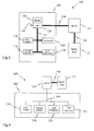
- FIG 3 there is shown therein a block diagram of a self service network 100 in the form of an ATM transaction network comprising an ATM 102 connected to a server 14 via a high order communications link 104 which is part of a wide area network.
- the link 104 provides efficient transfer of data from server 14 to ATM 102.
- a transaction database (or legacy host) 12 is also connected to server 14 via a conventional communications link 106.
- ATM 102 houses a plurality of peripherals including a card reader 116, a receipt printer 118, a cash dispenser 120, an encrypting keyboard 128 and a display 130 (the keyboard 128 and display 130 together form a user interface).
- a typical ATM keyboard will have a numeric keypad and a small number of additional keys, which may be labelled "ENTER”, "CANCEL” and so on.
- These peripherals 116,118,120,128,130 are connected by an RS-232 link 136 to a central processor 138 housed in ATM 102.
- ATM 102 also has a mass storage device 140 in the form of a hard disk.
- This hard disk 140 stores at least one device driver and at least one control application (similar to 30,32,34,36 in Fig 2) for each of the peripherals 116,118,120,128,130.
- a TCP/IP protocol is used for communication within ATM 102.
- the central processor 138 When power is applied to ATM 102, the central processor 138 is initialised, which involves the device drivers and the control applications being loaded into the central processor 138 from the mass storage device 140. Each control application is an independent process running on processor 138. Once the device drivers and control applications have been loaded into the central processor 138, the control applications implement a team-building process to form a team of peripherals, as will be described below.
- Fig 4A illustrates a completed functional group register 150 for the card reader control application.
- This register 150 has an entry for each peripheral that may be part of the team, including the card reader peripheral.
- Each entry has three fields: a peripheral identification field 152, a peripheral IP address field 154, and a port address field 156.
- the peripheral IP address field 154 is the address of the processor on which the control application associated with that peripheral is running.
- the peripheral IP address field 154 for each peripheral is the same, being the address of the processor 138 which runs all of the control applications.
- the address field 154 will contain the address of the relevant peripheral processor, i.e. the address field 154 of each peripheral will be different.
- the port address field 156 at which each peripheral receives signals is predetermined, having been written into the control application associated with that peripheral.
- the register 150 for the card reader control application will appear as shown in Fig 4B because the control application leaves all entries in the peripheral identification field 152 blank except the identification of its associated peripheral.
- a peripheral Even though a peripheral receives power, it may not be available for use and therefore may not be available to join the team. For example, a peripheral may have been shut down because of a malfunction, or because it needs replenished with paper (in the case of a receipt printer) or currency (in the case of a cash dispenser). Therefore, the card reader control application performs a test of the card reader to ensure that the card reader is functioning correctly. If the card reader is functioning correctly then the control application indicates its availability to join the team by broadcasting a start-up signal (a "HELLO" message) to other control applications.
- a start-up signal a "HELLO" message
- a broadcast message on a TCP/IP network uses a special reserved IP address (255.255.255.255) . Every node (every device having an IP address) connected to that TCP/IP network receives the broadcast message.
- the "HELLO" message includes an identifier for the peripheral being initialised and an address at which the peripheral receives signals.
- the card reader control application would transmit the identifier "card reader”, the processor address "178.132.152.212" (from processor IP address field 154), and the port address "6040" (from the port address field 156).
- the TCP stack within processor 138 would recognise that the IP address "178.132.152.212" relates only to itself and so would not transmit the broadcast over the physical layer.
- the control applications (running on processor 138) relating to the other peripherals would receive this "HELLO" message and if available to join the team would update their registers 150 accordingly.
- IP address used in this embodiment (178.132.152.212") is merely an example of a typical IP address.
- each peripheral control application maintains a register of the identity and address of all other active peripherals in the team.
- the individual control applications (similar to 30,32,34,36 in Fig 2) running on central processor 138 use client-server techniques to communicate with server 14 to obtain customer specific transactional information from legacy host 12.
- the team building process also allows display 130 to determine what peripherals are available and therefore what services should be displayed for offering to a user; those services which are not available being shown in a different colour, or not shown at all.
- control applications reside in the central processor 138 during operation of the ATM 102, each of the control applications is independent of the other control applications.
- a peripheral can withdraw from the team. This is effected by the control application for that peripheral sending a shut-down signal (a "GOODBYE" message) to indicate that it is no longer available.
- the "GOODBYE" message includes the identity of the peripheral that is withdrawing.
- Each control application in the team updates its register 150 by removing reference to the withdrawn peripheral from the register 150, thereby removing the peripheral from the team.
- the first application module that attempts to send a message to the now missing peripheral will detect that it is missing and send a "GOODBYE" message on its behalf.
- the "GOODBYE" message includes the identity of the missing peripheral rather than the identity of the peripheral sending the "GOODBYE” message.
- the control applications for the other (remaining) peripherals update their registers in response to this "GOODBYE" message.
- the individual control applications are arranged to operate as a team, with each application module being considered as a team member or peer.
- the control applications are event driven. Internal events (for example, user input or hardware activity) drive the state of each control application. As the state of a control application changes it transmits appropriate messages to all the other members of the team (i.e. all other active control applications). These event-based messages are used to enable other control applications to set themselves to an appropriate state.
- the state of any control application changes an event message is broadcast to allow the other members of the team to act appropriately.
- the state of a control application may change as a result of, for example, a hardware event, a user input, or a time-out condition.
- the ATM 102 operates as an event driven system. Messages are transmitted from the control application for a peripheral within which an event has occurred to other control applications within the ATM 102. These other control applications may, or may not, be concerned with that event.
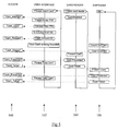
- a typical transaction sequence is illustrated in Fig 5 for ATM 102.
- the first column 160 shows a sequence of events and their associated event messages.
- the second 162, third 164 and fourth columns 166 show operations of display 130, card reader 116 and cash dispenser 120 following generation of each event message listed in the first column 160.
- the statements within quotation marks are examples of the text displayed to a user.
- ATM 102 is operating with a team of peripherals comprising: card reader 116, receipt printer 118, cash dispenser 120, keyboard 128, and display 130; in the event of insertion of a card by a new user into card reader 116 a message "CARD_INSERTED" is transmitted by the card reader control application to the other peripherals in the team.
- the effect of that message is to cause display 130 to display the text "Please enter PIN".
- a PIN personal identification number
- a 'Validate User PIN' operation takes place. This might involve the use of link 104 to communicate with legacy Host 12 via server 14. If the entered PIN is found to be valid for the particular card that has been inserted into card reader 116 then display 130 is informed accordingly whereupon its control application generates a "USER_VALID" event message. This causes display of a cash selection request. The user then enters a specific amount which causes the transmission of the next event message, namely "CASH_REQUEST".
- the "CASH_REQUEST” message causes operation of cash dispenser 120 to count out the requested amount while at the same time display 130 causes the text "Your cash is being counted” to be displayed on the screen.
- cash dispenser 120 has completed its task, its associated control application generates and transmits a "CASH_STAGED” message.
- card reader 116 presents the inserted card partly out of a card entry slot in ATM 102 to enable the card to be removed by the user.
- the control application associated with the card reader 116 then transmits the event message "CARD_PRESENTED" which in turn causes display 130 to display the text "Please take card”.
- card reader 116 may need to know the amount of any cash withdrawal figure entered by the user so that it can update the card appropriately should that cash withdrawal be validated by server 14 and dispensed by cash dispenser 120.
- Fig 5 Not shown in Fig 5 are the various communications that take place between individual peripherals and server 14 and legacy Host 12.
- FIG 6 illustrates an ATM transaction network 200 comprising an ATM 202 having a plurality of intelligent peripherals including a card reader 216, a receipt printer 218, a cash dispenser 220, and a user interface 222.
- User interface 222 includes both a keyboard and a display unit.
- peripherals in Fig 6 are configured so that they operate individually and independently of any central processor, each peripheral being operable: to communicate directly with the server 14; to download software therefrom; and to run the downloaded software directly on its own processor.
- peripherals of Fig 3 are controlled from a central processor 138 which: communicates directly with the server 14; downloads software from the hard disk 140; and runs the downloaded software to control the peripherals.
- control applications for the peripherals whether running on a central processor (Fig 3) or in the individual peripherals (Fig 6), communicate with each other and operate in response to signals generated by each other.
- each peripheral 216,218,220,222 has an embedded processor, associated volatile memory (for example 32Mbytes of RAM), non-volatile memory for booting-up the peripheral, and a TCP/IP network connection.
- ATM 202 is connected to server 214 by a communication link 204, which is part of a wide area network (WAN); where the WAN connects a plurality of ATMs to the server 214.
- Link 204 is a high bandwidth network connection to allow for efficient and rapid download of software and utilises the TCP/IP transfer protocol.
- a feature of communication link 204 is that each peripheral 216,218,220,222 in ATM 202 is directly and independently connected to server 214 through link 204 and is thus an individual client to server 214. This is required for this embodiment because each peripheral must be able to download software independently of the other peripherals.
- server 214 is connected to legacy Host 12 (which is a basic banking information database) through communications link 106.
- control applications software used by peripherals in ATM 202 is stored in server 214.
- the same applications software can also be used by corresponding peripherals in other terminals of the network 200 which are linked to server 214.
- control applications software can be updated at the server 214 and all associated peripherals will download the updated software, thereby centralising software upgrades.
- link 204 In addition to link 204 providing a direct connection from each peripheral 216,218,220,222 to server 214, link 204 also enables communication to take place between the individual peripherals 216,218,220,222 of ATM 202. Thus information as to the operational state of any of the peripherals 216,218,220,222 can be transmitted to all of the other peripherals 216,218,220,222.
- a peripheral e.g. 216
- a peripheral uses non-volatile memory to boot-up and then transmits a message to the server 214.
- the server uploads software to the peripheral to enable the peripheral to initialise and begin the team-building process.
- Fig 7 shows a typical functional group register 150' for the embodiment of Fig 6, where each peripheral in the terminal has a different IP address because the processor in each peripheral runs its associated control application.
- a request may be made by a peripheral to the server 214 for information specific to the user and appropriate to conduct the current transaction.
- the cash dispenser 220 will require the user's current balance to determine if the user has sufficient funds for a requested cash withdrawal.
- User interface 222 may require account balance and bank statement information to display these to the user.
- the function of the communications controller 38 illustrated in Fig 2 may be incorporated into the central processor 138 (Fig 3 embodiment) or may be incorporated into each peripheral 216,218,220,222 (Fig 6 embodiment), or may be a separate network router which routes data from each peripheral 216,218,220,222 (Fig 6 embodiment) to the server 214 (Fig 6 embodiment).
- the communications link 104 may be any convenient link and may be part of a local area network or it may be a dedicated link having a dial-up modem connection.
- the communication link 204 may be a low speed dial-up modem.
- a communications mechanism other than an RS-232 link 136 may be used, for example, a USB (universal serial bus), a Firewire, or an ethernet link may be used.
- a firewall may be used to ensure that the transactions are secure and to protect the peripheral devices from being accessed by unauthorised persons.
- the firewall may be implemented between server 14 and legacy host 12.
- the legacy host may be a retail information database.
- the addresses at which other peripherals may receive signals may be written into the control application for each peripheral so that each control application knows the address of its associated peripheral and all possible addresses of other peripherals.
- a different communications protocol may be used, for example, an RS232-based protocol may be used instead of TCP/IP.
Landscapes
- Business, Economics & Management (AREA)
- Accounting & Taxation (AREA)
- Finance (AREA)
- Physics & Mathematics (AREA)
- General Physics & Mathematics (AREA)
- Engineering & Computer Science (AREA)
- Software Systems (AREA)
- Strategic Management (AREA)
- General Business, Economics & Management (AREA)
- Theoretical Computer Science (AREA)
- Financial Or Insurance-Related Operations Such As Payment And Settlement (AREA)
- Cash Registers Or Receiving Machines (AREA)
- Control Of Vending Devices And Auxiliary Devices For Vending Devices (AREA)
Applications Claiming Priority (4)
| Application Number | Priority Date | Filing Date | Title |
|---|---|---|---|
| GBGB9808997.2A GB9808997D0 (en) | 1998-04-29 | 1998-04-29 | Banking and retail transaction terminal and network |
| GB9808997 | 1998-04-29 | ||
| US229045 | 1999-01-12 | ||
| US09/229,045 US6311165B1 (en) | 1998-04-29 | 1999-01-12 | Transaction processing systems |
Publications (2)
| Publication Number | Publication Date |
|---|---|
| EP0953947A2 true EP0953947A2 (de) | 1999-11-03 |
| EP0953947A3 EP0953947A3 (de) | 2003-05-21 |
Family
ID=26313549
Family Applications (1)
| Application Number | Title | Priority Date | Filing Date |
|---|---|---|---|
| EP99303209A Withdrawn EP0953947A3 (de) | 1998-04-29 | 1999-04-26 | Selbstbedienungsendgerät |
Country Status (3)
| Country | Link |
|---|---|
| EP (1) | EP0953947A3 (de) |
| JP (1) | JP4953404B2 (de) |
| BR (1) | BR9901331A (de) |
Cited By (5)
| Publication number | Priority date | Publication date | Assignee | Title |
|---|---|---|---|---|
| US6167381A (en) * | 1997-02-07 | 2000-12-26 | Ncr Corporation | Self-service checkout terminal |
| WO2004038666A1 (en) | 2002-10-28 | 2004-05-06 | Comfort-Netshare Kft. | System architecture enabling communication between intelligent and other electronic card handling devices and central servers on data transfer networks |
| USRE41717E1 (en) | 1999-11-02 | 2010-09-21 | Ncr Corporation | Apparatus and method for operating a checkout system having a display monitor which displays both transaction information and customer-specific messages during a checkout transaction |
| CN104346882A (zh) * | 2013-08-08 | 2015-02-11 | Ncr公司 | 交易执行 |
| US9003080B2 (en) | 2012-09-26 | 2015-04-07 | International Business Machines Corporation | Managed access to peripherals of a service terminal |
Families Citing this family (1)
| Publication number | Priority date | Publication date | Assignee | Title |
|---|---|---|---|---|
| US20170178099A1 (en) * | 2014-07-29 | 2017-06-22 | Hewlett-Packard Development Company, L.P. | Point of sale device |
Family Cites Families (15)
| Publication number | Priority date | Publication date | Assignee | Title |
|---|---|---|---|---|
| US4660168A (en) * | 1984-03-14 | 1987-04-21 | Grant Elwyn E | Apparatus for completing a customer initiated ATM transaction |
| US4636947A (en) * | 1984-03-14 | 1987-01-13 | Docutel/Olivetti Corporation | ATM task scheduling system for simultaneous peripheral device transactions processing |
| JPH01231155A (ja) * | 1988-03-11 | 1989-09-14 | Nec Off Syst Ltd | 周辺機器制御装置 |
| JP2998966B2 (ja) * | 1990-01-09 | 2000-01-17 | キヤノン株式会社 | 端末装置、ネットワーク接続方法およびその制御方法 |
| JPH03246796A (ja) * | 1990-02-26 | 1991-11-05 | Sharp Corp | Pos伝送制御システム |
| JP2605544B2 (ja) * | 1992-04-08 | 1997-04-30 | 三菱電機株式会社 | インタネットワーク装置 |
| JPH06110587A (ja) * | 1992-09-28 | 1994-04-22 | Omron Corp | 自動取引き機の電源制御方法とその装置 |
| DE69318259T2 (de) * | 1992-11-18 | 1998-09-17 | Canon Kk | Verfahren und Vorrichtung zur Implementierung einer Zweiwegeschnittstelle zwischen einem lokalen Netzwerk und einem Peripheriegerät |
| JP3444928B2 (ja) * | 1993-07-30 | 2003-09-08 | 富士通株式会社 | 冷却装置の運転制御システム |
| US5727184A (en) * | 1994-06-27 | 1998-03-10 | Cirrus Logic, Inc. | Method and apparatus for interfacing between peripherals of multiple formats and a single system bus |
| JP4251669B2 (ja) * | 1995-07-14 | 2009-04-08 | ソニー株式会社 | データ処理方法および装置 |
| JPH09115222A (ja) * | 1995-10-18 | 1997-05-02 | Sony Corp | コンピュータ |
| JPH09261259A (ja) * | 1996-03-27 | 1997-10-03 | Canon Inc | ネットワークシステム及びノード装置及びその伝送制御方法 |
| KR100214497B1 (ko) * | 1996-07-15 | 1999-08-02 | 구본준 | 마이크로 콘트롤러의 어드레스 재설정 회로 |
| JPH1055332A (ja) * | 1996-08-09 | 1998-02-24 | Seiko Epson Corp | 情報処理システム管理装置、pos端末システムおよびシステムの自動構築方法 |
-
1999
- 1999-04-26 EP EP99303209A patent/EP0953947A3/de not_active Withdrawn
- 1999-04-29 BR BR9901331-2A patent/BR9901331A/pt not_active Application Discontinuation
- 1999-04-30 JP JP12354499A patent/JP4953404B2/ja not_active Expired - Lifetime
Cited By (6)
| Publication number | Priority date | Publication date | Assignee | Title |
|---|---|---|---|---|
| US6167381A (en) * | 1997-02-07 | 2000-12-26 | Ncr Corporation | Self-service checkout terminal |
| USRE41717E1 (en) | 1999-11-02 | 2010-09-21 | Ncr Corporation | Apparatus and method for operating a checkout system having a display monitor which displays both transaction information and customer-specific messages during a checkout transaction |
| WO2004038666A1 (en) | 2002-10-28 | 2004-05-06 | Comfort-Netshare Kft. | System architecture enabling communication between intelligent and other electronic card handling devices and central servers on data transfer networks |
| US9003080B2 (en) | 2012-09-26 | 2015-04-07 | International Business Machines Corporation | Managed access to peripherals of a service terminal |
| CN104346882A (zh) * | 2013-08-08 | 2015-02-11 | Ncr公司 | 交易执行 |
| US10956892B2 (en) | 2013-08-08 | 2021-03-23 | Ncr Corporation | Transaction performance |
Also Published As
| Publication number | Publication date |
|---|---|
| EP0953947A3 (de) | 2003-05-21 |
| JP4953404B2 (ja) | 2012-06-13 |
| BR9901331A (pt) | 2000-01-18 |
| JPH11353406A (ja) | 1999-12-24 |
Similar Documents
| Publication | Publication Date | Title |
|---|---|---|
| US7912914B2 (en) | Transaction processing systems | |
| US7542944B1 (en) | Method and system for connecting services to an automated transaction machine | |
| US7934644B2 (en) | Card activated cash dispensing automated transaction machine system and method | |
| EP0961249B1 (de) | Systemkonfiguration, bei der bestimmte Transaktionsvorrichtungen mit einer Browser-Schnittstelle zu HTTP und andere Vorrichtungen nach Berichten aus einem Geldautomaten-Vermächtnissystem arbeiten | |
| US8870064B2 (en) | Self-service terminal management | |
| US20050119973A1 (en) | Automated banking machine with record accessibility pre-check | |
| US20020026421A1 (en) | Automated banking machine and system | |
| EP2042990A2 (de) | Lieferantenunabhängiger Proxy zur Selbstbedienung | |
| US20090159661A1 (en) | Self-service terminal | |
| RU2255371C2 (ru) | Система автоматизированных банковских машин и способ усовершенствования | |
| US20030116621A1 (en) | Self-service terminal | |
| US9680660B2 (en) | Self-service terminal | |
| WO2002023339A1 (en) | System and method for providing security for financial services terminals with a document driven interface | |
| US20040129775A1 (en) | Cash dispensing automated banking machine and method | |
| EP1659548A2 (de) | Überwachungsprogramm | |
| RU2251730C2 (ru) | Автоматизированная система и способ для выполнения финансовых операций | |
| EP0953947A2 (de) | Selbstbedienungsendgerät | |
| US7003492B1 (en) | Apparatus and method for indicating the status of transaction function devices in an automated banking machine | |
| EP0961247B1 (de) | Nach entsprechenden HTML-Dokumenten, auf welche mit einem Browser zugegriffen wird, arbeitender automatischer Geldautomat | |
| EP0953946A2 (de) | Transaktionsnetzen | |
| MXPA99004930A (es) | Sistema y aparato de maquina de cajero automatizado. | |
| EP0961251B1 (de) | Automatischer Geldautomat mit Zugriff auf Daten basierend auf Gebrauchereingaben mit unter anderem biometrischer Gebrauchersidentifikation und Herstellung vorbestimmter Bildanzeigen basierend auf Gebraucheridentität (Profil Bean) | |
| MXPA99004939A (es) | Sistema y aparato de maquina de cajero automatizado. | |
| EP1030495B1 (de) | Vornavigations-Bean (mit Fernladungsgeschwindigkeitstest zum Feststellen ob Zugriff zu HTTP-Datensätzen möglich ist) | |
| CN100382071C (zh) | 自动化银行业务机和系统 |
Legal Events
| Date | Code | Title | Description |
|---|---|---|---|
| PUAI | Public reference made under article 153(3) epc to a published international application that has entered the european phase |
Free format text: ORIGINAL CODE: 0009012 |
|
| AK | Designated contracting states |
Kind code of ref document: A2 Designated state(s): AT BE CH CY DE DK ES FI FR GB GR IE IT LI LU MC NL PT SE |
|
| AX | Request for extension of the european patent |
Free format text: AL;LT;LV;MK;RO;SI |
|
| RIN1 | Information on inventor provided before grant (corrected) |
Inventor name: DOVE, LEE G. Inventor name: COUTTS, MICHAEL G. |
|
| PUAL | Search report despatched |
Free format text: ORIGINAL CODE: 0009013 |
|
| AK | Designated contracting states |
Designated state(s): AT BE CH CY DE DK ES FI FR GB GR IE IT LI LU MC NL PT SE |
|
| AX | Request for extension of the european patent |
Extension state: AL LT LV MK RO SI |
|
| 17P | Request for examination filed |
Effective date: 20031121 |
|
| 17Q | First examination report despatched |
Effective date: 20031222 |
|
| AKX | Designation fees paid |
Designated state(s): DE ES FR GB IT |
|
| STAA | Information on the status of an ep patent application or granted ep patent |
Free format text: STATUS: THE APPLICATION IS DEEMED TO BE WITHDRAWN |
|
| 18D | Application deemed to be withdrawn |
Effective date: 20051105 |