EP0953498B1 - Aufschiebestück für ein Gleiskettenglied - Google Patents
Aufschiebestück für ein Gleiskettenglied Download PDFInfo
- Publication number
- EP0953498B1 EP0953498B1 EP99107813A EP99107813A EP0953498B1 EP 0953498 B1 EP0953498 B1 EP 0953498B1 EP 99107813 A EP99107813 A EP 99107813A EP 99107813 A EP99107813 A EP 99107813A EP 0953498 B1 EP0953498 B1 EP 0953498B1
- Authority
- EP
- European Patent Office
- Prior art keywords
- base plate
- track link
- stop
- tongue
- caterpillar track
- Prior art date
- Legal status (The legal status is an assumption and is not a legal conclusion. Google has not performed a legal analysis and makes no representation as to the accuracy of the status listed.)
- Expired - Lifetime
Links
- 238000005520 cutting process Methods 0.000 claims description 4
- 238000004049 embossing Methods 0.000 claims description 2
- 238000007493 shaping process Methods 0.000 claims 2
- 239000002585 base Substances 0.000 description 34
- 229920001971 elastomer Polymers 0.000 description 5
- 230000015572 biosynthetic process Effects 0.000 description 2
- 238000007373 indentation Methods 0.000 description 2
- 238000004080 punching Methods 0.000 description 2
- 229910000831 Steel Inorganic materials 0.000 description 1
- 239000011324 bead Substances 0.000 description 1
- 238000005452 bending Methods 0.000 description 1
- 238000005336 cracking Methods 0.000 description 1
- 230000001419 dependent effect Effects 0.000 description 1
- 238000011161 development Methods 0.000 description 1
- 230000018109 developmental process Effects 0.000 description 1
- 230000000694 effects Effects 0.000 description 1
- 239000000806 elastomer Substances 0.000 description 1
- 239000012458 free base Substances 0.000 description 1
- 239000002184 metal Substances 0.000 description 1
- 239000004033 plastic Substances 0.000 description 1
- 230000002787 reinforcement Effects 0.000 description 1
- 230000003014 reinforcing effect Effects 0.000 description 1
- 230000035939 shock Effects 0.000 description 1
- 239000010959 steel Substances 0.000 description 1
- 230000008719 thickening Effects 0.000 description 1
- 238000004073 vulcanization Methods 0.000 description 1
Images



Classifications
-
- B—PERFORMING OPERATIONS; TRANSPORTING
- B62—LAND VEHICLES FOR TRAVELLING OTHERWISE THAN ON RAILS
- B62D—MOTOR VEHICLES; TRAILERS
- B62D55/00—Endless track vehicles
- B62D55/08—Endless track units; Parts thereof
- B62D55/18—Tracks
- B62D55/26—Ground engaging parts or elements
-
- B—PERFORMING OPERATIONS; TRANSPORTING
- B62—LAND VEHICLES FOR TRAVELLING OTHERWISE THAN ON RAILS
- B62D—MOTOR VEHICLES; TRAILERS
- B62D55/00—Endless track vehicles
- B62D55/08—Endless track units; Parts thereof
- B62D55/18—Tracks
- B62D55/26—Ground engaging parts or elements
- B62D55/275—Ground engaging parts or elements with street plate, i.e. means to prevent tread from cutting into road surface
Definitions
- the invention relates to a track link according to the preamble of Claim 1.
- the track link consists of a base body with guide grooves and a Detent.
- the slide has a spring-loaded base plate with a punched-out Tongue.
- When pushing the running pad slides in the track member the tongue over the stop and is deformed accordingly until the tongue snaps behind the stop.
- pushing out the running pad from the Track link is the tongue due to a in a recess of the body plug lever lifted above the stop.
- a running pad according to WO 96/29234 A has in the rubber body specifically embedded reinforcing elements in the form of Z-shaped angle plates. Due to the only partial reinforcement of the plastic base plate By means of these angle plates is the running cushion while driving a caterpillar subjected to extreme deformations leading to a resolution of the Locking function of the angle plates in the track member can lead. Here too There is a risk of uncontrolled detachment of padding from the Track links.
- the invention is based on the object, the Aufschiebe consensus so form that cracks and breaks on base plates of sliding pieces for caterpillars do not occur.
- the solution to this problem is not to cut and unlatch the securing tongue of the base plate, but to provide the base plate with an embossing in the area of the previous notched tongue, which performs the function of the tongue detent.
- the base plate is no longer weakened by the cuts. There is no longer a notch factor which has significantly increased component stress. A thickening of the base plate is not required. Thus, the weight of the sheet metal part is not increased.
- the slide-on piece can be easily assembled and disassembled using the existing tools on board. Tests carried out have shown that no cracks and cracks have occurred on the base plates over the service life of the slide-on piece. By eliminating the incisions in the base plate, there is a cost reduction.
- the base plate 4 is engaged between two stops 5, 6, see rest area 10.
- the base plate 4 elastically deformed.
- the base plate is the 4th via a dashed line recess 7 by means of a not shown Tool 11 to lift over the stop 6 and about a eintechnischdes at the arrow 8, also lever out unillustrated tool.
- the base plate 4 lies in a main plane 9. It is nick-free, so as a tongue-free base plate 4 formed.
- the main level 9 and the Tongue 16 form an angle 17. This causes a frictional contact during Pushing in or pushing out the running pad 13 from the tubular body 2 only between the tongue 15 and the stop 6.
- the deformation zones in the locking portion 10, the lead to the formation of the tongue 15 are described to Fig. 7.
- 4 is in a running pad 23 - analogous to Figs. 2, 7 a Base plate 24 with a formed by cutting deformation tongue 25th in the locking area 10 before.
- the base plate 24 extends in terms of area to the largest Part about the running pad 23.
- An elastomer layer 26 is located between a wear-resistant steel body 27, the dash-dotted lines in the guide 1 drawn tubular body 22 engages.
- the base plate 24 is analogous to the Stops 5, 6 of FIGS. 1 and 2 also between stops 28, 29.
- a Recess for lifting the tongue 25 from the tubular body 22 are designated 30.
- a running cushion fixed in a tubular body 32 is located 33 a base plate 34 according to the figures 2 and 4 before.
- the base plate 34 has two deformation zones 36 in the latching area 10 on these deformation zones 36 cause the formation of a tongue 35 according to the Angle 17 with respect to the main plane 9, see Fig. 2.
- the base plate 34 is a carrier the running pad 33 and at the same time it serves for the positive connection with the tubular body 32 by engagement in the guide grooves 31 of the tubular body 32.
- a recess 40 serves to disengage the tongue 35 on the stop 39th
- tubular body 51 with guide teeth 52nd over arranged in the tubular bodies 51, rubber bearing bolt 53 and thereon fastened connectors 54 hinged together.
- Each tubular body 51 has guide grooves 55 and stops 56, 57 for fixing a running pad 63.
- the insertion-side stop bears the numbers 56 and the back stop is the number 57.
- an intermediate plate 64 with guide strips is provided 65 for the guide grooves 55 and a base plate 74 with a tongue 75 connected by vulcanization.
- the tongue 75 is in the latching area 10 by Rubber lined.
- the tongue 75 of the base plate 74 has, according to FIG. 8, a double waveform on. This is achieved by the three deformation zones apparent from FIG 76, 77 causes.
- the base plate 74 has an end stop 78. This corresponds with a rear wall 79 with the stop 57 of the tubular body 51st
- the stop 56 of the tubular body 51 is provided with a central indentation 80, which corresponds to an opposite indentation 81 of the running pad 63.
Landscapes
- Engineering & Computer Science (AREA)
- Combustion & Propulsion (AREA)
- Transportation (AREA)
- Mechanical Engineering (AREA)
- Chemical & Material Sciences (AREA)
- Handcart (AREA)
- Bearings For Parts Moving Linearly (AREA)
- Braking Arrangements (AREA)
- Pallets (AREA)
- Soil Working Implements (AREA)
- Escalators And Moving Walkways (AREA)
- Chain Conveyers (AREA)
- Purses, Travelling Bags, Baskets, Or Suitcases (AREA)
Description
Insbesondere bei hochmobilen Fahrzeugen kommt es durch Überbelastung häufig zu Anrissen im Grundblech, die in der Regel von dem Grund des Einschnittes der Zungenraste ausgehen. Werden die Anrisse nicht frühzeitig genug bemerkt oder Laufpolster mit angerissenen Grundblechen aufgrund des Gummiverschleißes nicht ausgebaut, so kommt es zum Durchbruch des Grundbleches. Laufpolster mit durchgebrochenen Grundblechen stellen eine potentielle Gefahr dar, da sie im Fahrbetrieb von der Kette abfliegen können.
Es wurden verschiedene Anstrengungen unternommen, die Anrißgefahr zu vermeiden oder zu reduzieren. Dazu wurde zum Beispiel der Kerbformfaktor durch Einbringen eines größeren Radius im Einschnittbereich der Zunge, sowie die Festlegung der Stanzrichtung beim Schneidvorgang zur Vermeidung von Beanspruchungsspitzen auf der Biegezugseite eingebracht. Auch eine Vergrößerung der Ausgangsblechdicke wurde versucht. Die Maßnahmen konnten die Rißproblematik nicht endgültig lösen.
Das Grundblech ist nun nicht mehr durch die Einschnitte geschwächt. Es gibt keinen Kerbformfaktor mehr, der die Bauteilbeanspruchung erheblich erhöht hatte. Eine Verdickung des Grundbleches ist nicht erforderlich. Damit wird auch das Gewicht des Blechteiles nicht erhöht. Das Aufschiebestück ist in einfacher Weise durch die vorhandenen Bordwerkzeuge zu montieren und zu demontieren.
Durchgeführte Erprobungen haben gezeigt, daß über die Nutzungsdauer des Aufschiebestücks keine Anrisse und Brüche an den Grundblechen aufgetreten sind. Durch Wegfall der Einschnitte im Grundblech kommt es zu einer Kostensenkung.
- Fig. 1, 2
- Laufpolster in einem Gleiskettenglied im Querschnitt,
- Fig. 3
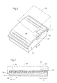
- ein Laufpolster in einem Gleiskettenglied in perspektivischer Ansicht,
- Fig. 4
- einen Schnitt IV - IV nach Fig. 3,
- Fig. 5
- ein weiteres Laufpolster im Querschnitt in einem Gleiskettenglied,
- Fig. 6
- einen Schnitt VI - VI nach Fig. 5,
- Fig. 7
- ein Grundblech des Laufpolsters nach Fig. 5,
- Fig. 8
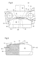
- einen Abschnitt einer Gleiskette mit einem Laufpolster,
- Fig. 9
- einen Teilschnitt eines Laufpolsters nach Fig. 8,
- Fig. 10
- ein Grundblech des Laufpolsters nach den Fig. 8, 9 und
- Fig. 11
- einen Querschnitt XI - XI nach Fig. 10.
Claims (8)
- Gleiskettenglied bestehend aus einem Grundkörper (2, 32) mit Führungsnuten (31) und einer Rastung (6, 10) für Aufschiebestücke (3, 33), wie Laufpolster, Stollen, Schnee- oder Schlammgreifer, Schwimmhilfen,
wobei das Aufschiebestück (3, 33) ein federndes Grundblech (4, 14, 34) aufweist, das an einem Anschlag (6, 39) mit zugeordneter Ausnehmung (7, 40) des Grundkörpers (2, 32) eingerastet ist,
das Aufschiebestück (3, 33) in den Führungsnuten (1, 31) des Grundkörpers (2, 32) liegt,
wobei das Grundblech (4, 34) über den Anschlag (6, 39) des Grundkörpers (32) beim Ein- und Ausschieben gleitet,
und beim Ausschieben das Grundblechs (4, 34) aufgrund eines, in die Ausnehmung (7, 40) steckbaren Hebels über den Anschlag (6, 39) hebbar ist,
dadurch gekennzeichnet, daß das Grundblech (4) entweder im Rastungsbereich (10) einschnittsfrei, also zungenfrei ausgebildet ist oder
das Grundblech (14, 34) im Rastbereich (10) durch spanloses Verformen geformte Verformungszonen (36, 76) aufweist. - Gleiskettenglied nach Anspruch 1,
dadurch gekennzeichnet, daß das Grundblech (4) im Rastbereich (10) in der Hauptebene (9) des Grundbleches (4) liegt. - Gleiskettenglied nach Anspruch 1,
dadurch gekennzeichnet, daß das Grundblech (14) im Rastbereich (10) mit der Hauptebene (9) des Grundblechs (14) einen Winkel (17) bildet. - Gleiskettenglied nach Anspruch 3,
dadurch gekennzeichnet, daß das Grundblech (14) im Rastbereich (10) durch spanloses Verformen, wie Prägen, den Winkel (17) bildet. - Gleiskettenglied nach Anspruch 1,
dadurch gekennzeichnet, daß das in einem Laufpolster von einem Zwischenblech (64) beabstandete Grundblech (74) zungenfrei ausgebildet ist,
und das Zwischenblech mit Führungsleisten (65) in die Führungsnuten (1) des Rohrkörpers (51) greift. - Gleiskettenglied nach Anspruch 1,
dadurch gekennzeichnet, daß eine durch die Verformungszonen (36, 76) gebildete Zunge (15) in Schieberichtung in Bezug auf den überbrückbaren Anschlag (6) für die Zunge (15) eine Anlaufschräge (Winkel 17) aufweist. - Gleiskettenglied nach Anspruch 1,
dadurch gekennzeichnet, daß das Grundblech (4) im Bereich des Anschlags (6) eine durchgehende, nicht unterbrochene Stirnfläche aufweist. - Gleiskettenglied nach Anspruch 7,
dadurch gekennzeichnet, daß das Grundblech (74) eine durch Verformungszonen (76, 77) bewirkte, doppelte Wölbung als Anschlag besitzt.
Applications Claiming Priority (2)
| Application Number | Priority Date | Filing Date | Title |
|---|---|---|---|
| DE19820175 | 1998-04-29 | ||
| DE19820175A DE19820175C1 (de) | 1998-04-29 | 1998-04-29 | Gleiskettenglied |
Publications (2)
| Publication Number | Publication Date |
|---|---|
| EP0953498A1 EP0953498A1 (de) | 1999-11-03 |
| EP0953498B1 true EP0953498B1 (de) | 2003-07-02 |
Family
ID=7866818
Family Applications (1)
| Application Number | Title | Priority Date | Filing Date |
|---|---|---|---|
| EP99107813A Expired - Lifetime EP0953498B1 (de) | 1998-04-29 | 1999-04-20 | Aufschiebestück für ein Gleiskettenglied |
Country Status (13)
| Country | Link |
|---|---|
| US (1) | US6217135B1 (de) |
| EP (1) | EP0953498B1 (de) |
| JP (1) | JP4145420B2 (de) |
| KR (1) | KR100468191B1 (de) |
| AR (1) | AR014787A1 (de) |
| AT (1) | ATE244182T1 (de) |
| AU (1) | AU752068B2 (de) |
| BR (1) | BR9901316A (de) |
| CA (1) | CA2269347C (de) |
| DE (2) | DE19820175C1 (de) |
| ES (1) | ES2202958T3 (de) |
| IL (1) | IL129396A (de) |
| TR (1) | TR199900735A3 (de) |
Cited By (1)
| Publication number | Priority date | Publication date | Assignee | Title |
|---|---|---|---|---|
| DE102007019769B3 (de) * | 2007-04-25 | 2008-07-24 | Bundesrepublik Deutschland, vertreten durch das Bundesministerium der Verteidigung, vertreten durch das Bundesamt für Wehrtechnik und Beschaffung | Aufschiebestück für ein Gleiskettenglied |
Families Citing this family (6)
| Publication number | Priority date | Publication date | Assignee | Title |
|---|---|---|---|---|
| JP2002059876A (ja) * | 2000-03-22 | 2002-02-26 | Topy Ind Ltd | 履帯およびその製造方法 |
| GB2360750B (en) * | 2000-03-31 | 2002-06-12 | William Cook Cast Products Ltd | Articulated vehicle track components and methods and tools for their removal |
| DE102008035182A1 (de) | 2008-07-28 | 2010-02-04 | Gmt Gummi-Metall-Technik Gmbh | Kettenpolster für ein Kettenglied |
| DE202008010111U1 (de) | 2008-07-28 | 2008-12-11 | Gmt Gummi-Metall-Technik Gmbh | Kettenpolster für ein Kettenglied |
| DE202019000037U1 (de) * | 2019-01-09 | 2020-01-13 | FSB Forst- und Baumaschinen Service Burkhardt GmbH | Kettenlaufwerk |
| DE202019001168U1 (de) | 2019-03-13 | 2020-03-18 | Street-Rubbers GmbH & Co. KG | Kettenlaufwerk |
Family Cites Families (10)
| Publication number | Priority date | Publication date | Assignee | Title |
|---|---|---|---|---|
| DE1605509B1 (de) * | 1963-08-24 | 1970-06-04 | Diehl Kg | Gleiskettenglied fuer Fahrzeuge |
| FR95351E (fr) * | 1963-08-24 | 1970-09-11 | Diehl K G | Maillon de chenille de véhicule. |
| US3266853A (en) * | 1963-08-24 | 1966-08-16 | Diehl Fa | Track link units |
| DE1932494U (de) * | 1965-06-12 | 1966-02-10 | Schmiede Und Stanzwerk Halver | Gleiskettenglied, insbesondere fuer panzerfahrzeuge. |
| DE1996393U (de) * | 1968-04-09 | 1968-11-07 | Diehl K G Fa | Gleiskette mit ein- oder doppelseitigem belag ihrer kettenglieder |
| GB1405742A (en) * | 1973-02-16 | 1975-09-10 | Diehl | Track link for a tracke vehicle |
| DE3173761D1 (en) | 1980-07-14 | 1986-03-27 | Secr Defence Brit | Track link for a tracked vehicle |
| DE3335937A1 (de) * | 1983-10-04 | 1985-04-18 | Hoesch Ag, 4600 Dortmund | Aufschiebestueck fuer gleiskettenglieder |
| GB9505515D0 (en) | 1995-03-18 | 1995-05-03 | William Cook Cast Products Lim | Roads pads for tracked vehicles |
| DE19544458C2 (de) * | 1995-11-29 | 1999-03-04 | Diehl Remscheid Gmbh & Co | Aufschiebestück für ein Gleiskettenglied |
-
1998
- 1998-04-29 DE DE19820175A patent/DE19820175C1/de not_active Expired - Fee Related
-
1999
- 1999-03-26 AR ARP990101369A patent/AR014787A1/es unknown
- 1999-03-29 US US09/280,874 patent/US6217135B1/en not_active Expired - Lifetime
- 1999-04-02 TR TR1999/00735A patent/TR199900735A3/tr unknown
- 1999-04-12 IL IL12939699A patent/IL129396A/en not_active IP Right Cessation
- 1999-04-14 AU AU23734/99A patent/AU752068B2/en not_active Expired
- 1999-04-15 CA CA002269347A patent/CA2269347C/en not_active Expired - Lifetime
- 1999-04-20 ES ES99107813T patent/ES2202958T3/es not_active Expired - Lifetime
- 1999-04-20 EP EP99107813A patent/EP0953498B1/de not_active Expired - Lifetime
- 1999-04-20 AT AT99107813T patent/ATE244182T1/de active
- 1999-04-20 DE DE59906152T patent/DE59906152D1/de not_active Expired - Lifetime
- 1999-04-29 KR KR10-1999-0015474A patent/KR100468191B1/ko not_active Expired - Lifetime
- 1999-04-29 BR BR9901316A patent/BR9901316A/pt not_active IP Right Cessation
- 1999-04-30 JP JP12472999A patent/JP4145420B2/ja not_active Expired - Lifetime
Cited By (1)
| Publication number | Priority date | Publication date | Assignee | Title |
|---|---|---|---|---|
| DE102007019769B3 (de) * | 2007-04-25 | 2008-07-24 | Bundesrepublik Deutschland, vertreten durch das Bundesministerium der Verteidigung, vertreten durch das Bundesamt für Wehrtechnik und Beschaffung | Aufschiebestück für ein Gleiskettenglied |
Also Published As
| Publication number | Publication date |
|---|---|
| KR19990083613A (ko) | 1999-11-25 |
| JP4145420B2 (ja) | 2008-09-03 |
| IL129396A0 (en) | 2000-02-17 |
| IL129396A (en) | 2002-05-23 |
| JP2000203471A (ja) | 2000-07-25 |
| CA2269347C (en) | 2006-01-03 |
| CA2269347A1 (en) | 1999-10-29 |
| DE19820175C1 (de) | 1999-12-30 |
| ATE244182T1 (de) | 2003-07-15 |
| AU752068B2 (en) | 2002-09-05 |
| TR199900735A2 (xx) | 1999-11-22 |
| AR014787A1 (es) | 2001-03-28 |
| DE59906152D1 (de) | 2003-08-07 |
| US6217135B1 (en) | 2001-04-17 |
| ES2202958T3 (es) | 2004-04-01 |
| KR100468191B1 (ko) | 2005-01-26 |
| BR9901316A (pt) | 2000-03-21 |
| AU2373499A (en) | 1999-11-11 |
| TR199900735A3 (tr) | 1999-11-22 |
| EP0953498A1 (de) | 1999-11-03 |
Similar Documents
| Publication | Publication Date | Title |
|---|---|---|
| DE3306490C2 (de) | Zahnriementrieb | |
| DE3616716A1 (de) | Laminiertes metallisches band fuer drehmomentuebertragungseinrichtungen sowie verfahren zu dessen herstellung | |
| DE102009050509A1 (de) | Unrunde Gelenköffnungen in Zahnlaschen von Zahnlaschenketten | |
| DE102011118421A1 (de) | Gleiskette oder Gleiskettensegment | |
| EP2824364A1 (de) | Gelenkkette mit reibungsreduziertem Laschenrücken | |
| DE2155319C3 (de) | Mit einer Gleiskette versehenes Rad, insbesondere für Erdbewegungs-und Transportfahrzeuge | |
| DE3300288A1 (de) | Dichtung fuer eine gelenkverbindung in einem spurkettengelenk eines raupenfahrzeuges | |
| DE19820175C1 (de) | Gleiskettenglied | |
| DE10209680B4 (de) | Sägekette | |
| EP0552387B1 (de) | Kfz-Kupplungs-Mitnehmerscheibe | |
| DE69618004T2 (de) | Fahrradfelge aus leichtmetall | |
| DE69818403T2 (de) | Gleiskettenglied mit Flansch für endlose Raupenkette und Verfahren zu dessen Herstellung | |
| DE102008037537A1 (de) | Zugmitteltrieb und Aufzugsanlage mit diesem Zugmitteltrieb | |
| DE102020200623A1 (de) | Fahrradkette | |
| DE2234624A1 (de) | Aus einzelnen kettenabschnitten bestehende kette fuer raupenschlepper od. dgl | |
| DE102007047602A1 (de) | Schaltgabel mit Gleitschuhen | |
| DE3134857A1 (de) | Schmiedeverfahren | |
| WO2001008964A1 (de) | Gleiskettenglied | |
| DE19544458C2 (de) | Aufschiebestück für ein Gleiskettenglied | |
| EP0966625A1 (de) | Kettenschloss | |
| DE29506363U1 (de) | Verbessertes Raupenglied, insbesondere zur Anwendung in Raupenmaschinen geringer Leistungsfähigkeit | |
| DE102004020857A1 (de) | Verstärkungsträger, Dichtung mit einem solchen Verstärkungsträger und Verfahren zum Herstellen einer solchen Dichtung | |
| DE19824755A1 (de) | Pedalüberzugkappe | |
| WO2000075063A1 (de) | Kettenrad für gelenkketten und dämpfungseinrichtung | |
| DE19824445B4 (de) | Elastomerlager |
Legal Events
| Date | Code | Title | Description |
|---|---|---|---|
| PUAI | Public reference made under article 153(3) epc to a published international application that has entered the european phase |
Free format text: ORIGINAL CODE: 0009012 |
|
| AK | Designated contracting states |
Kind code of ref document: A1 Designated state(s): AT BE CH DE DK ES FR GB GR IT LI NL PT SE |
|
| AX | Request for extension of the european patent |
Free format text: AL;LT;LV;MK;RO;SI |
|
| 17P | Request for examination filed |
Effective date: 19990925 |
|
| AKX | Designation fees paid |
Free format text: AT BE CH DE DK ES FR GB GR IT LI NL PT SE |
|
| 17Q | First examination report despatched |
Effective date: 20000919 |
|
| GRAG | Despatch of communication of intention to grant |
Free format text: ORIGINAL CODE: EPIDOS AGRA |
|
| GRAG | Despatch of communication of intention to grant |
Free format text: ORIGINAL CODE: EPIDOS AGRA |
|
| GRAH | Despatch of communication of intention to grant a patent |
Free format text: ORIGINAL CODE: EPIDOS IGRA |
|
| GRAH | Despatch of communication of intention to grant a patent |
Free format text: ORIGINAL CODE: EPIDOS IGRA |
|
| GRAG | Despatch of communication of intention to grant |
Free format text: ORIGINAL CODE: EPIDOS AGRA |
|
| GRAH | Despatch of communication of intention to grant a patent |
Free format text: ORIGINAL CODE: EPIDOS IGRA |
|
| GRAA | (expected) grant |
Free format text: ORIGINAL CODE: 0009210 |
|
| AK | Designated contracting states |
Designated state(s): AT BE CH DE DK ES FR GB GR IT LI NL PT SE |
|
| REG | Reference to a national code |
Ref country code: GB Ref legal event code: FG4D Free format text: NOT ENGLISH |
|
| REG | Reference to a national code |
Ref country code: CH Ref legal event code: EP |
|
| REF | Corresponds to: |
Ref document number: 59906152 Country of ref document: DE Date of ref document: 20030807 Kind code of ref document: P |
|
| PG25 | Lapsed in a contracting state [announced via postgrant information from national office to epo] |
Ref country code: PT Free format text: LAPSE BECAUSE OF FAILURE TO SUBMIT A TRANSLATION OF THE DESCRIPTION OR TO PAY THE FEE WITHIN THE PRESCRIBED TIME-LIMIT Effective date: 20031002 Ref country code: DK Free format text: LAPSE BECAUSE OF FAILURE TO SUBMIT A TRANSLATION OF THE DESCRIPTION OR TO PAY THE FEE WITHIN THE PRESCRIBED TIME-LIMIT Effective date: 20031002 |
|
| REG | Reference to a national code |
Ref country code: SE Ref legal event code: TRGR |
|
| REG | Reference to a national code |
Ref country code: GR Ref legal event code: EP Ref document number: 20030403822 Country of ref document: GR |
|
| REG | Reference to a national code |
Ref country code: CH Ref legal event code: NV Representative=s name: A. BRAUN, BRAUN, HERITIER, ESCHMANN AG PATENTANWAE |
|
| GBT | Gb: translation of ep patent filed (gb section 77(6)(a)/1977) |
Effective date: 20031028 |
|
| REG | Reference to a national code |
Ref country code: ES Ref legal event code: FG2A Ref document number: 2202958 Country of ref document: ES Kind code of ref document: T3 |
|
| PLBE | No opposition filed within time limit |
Free format text: ORIGINAL CODE: 0009261 |
|
| STAA | Information on the status of an ep patent application or granted ep patent |
Free format text: STATUS: NO OPPOSITION FILED WITHIN TIME LIMIT |
|
| ET | Fr: translation filed | ||
| 26N | No opposition filed |
Effective date: 20040405 |
|
| REG | Reference to a national code |
Ref country code: CH Ref legal event code: PFA Owner name: DIEHL REMSCHEID GMBH & CO. Free format text: DIEHL REMSCHEID GMBH & CO.#VIERINGHAUSEN 118#D-42857 REMSCHEID (DE) -TRANSFER TO- DIEHL REMSCHEID GMBH & CO.#VIERINGHAUSEN 118#D-42857 REMSCHEID (DE) |
|
| REG | Reference to a national code |
Ref country code: DE Ref legal event code: R081 Ref document number: 59906152 Country of ref document: DE Owner name: DST DEFENCE SERVICE TRACKS GMBH, DE Free format text: FORMER OWNER: DIEHL REMSCHEID GMBH & CO.KG, 42857 REMSCHEID, DE Effective date: 20120207 Ref country code: DE Ref legal event code: R081 Ref document number: 59906152 Country of ref document: DE Owner name: DIEHL DEFENCE LAND SYSTEMS GMBH, DE Free format text: FORMER OWNER: DIEHL REMSCHEID GMBH & CO.KG, 42857 REMSCHEID, DE Effective date: 20120207 |
|
| REG | Reference to a national code |
Ref country code: CH Ref legal event code: PCAR Free format text: NEW ADDRESS: HOLBEINSTRASSE 36-38, 4051 BASEL (CH) |
|
| REG | Reference to a national code |
Ref country code: FR Ref legal event code: PLFP Year of fee payment: 17 |
|
| REG | Reference to a national code |
Ref country code: DE Ref legal event code: R082 Ref document number: 59906152 Country of ref document: DE Representative=s name: FEDER WALTER EBERT PATENTANWAELTE, DE Ref country code: DE Ref legal event code: R081 Ref document number: 59906152 Country of ref document: DE Owner name: DST DEFENCE SERVICE TRACKS GMBH, DE Free format text: FORMER OWNER: DIEHL DEFENCE LAND SYSTEMS GMBH, 66629 FREISEN, DE |
|
| REG | Reference to a national code |
Ref country code: FR Ref legal event code: TP Owner name: DIEHL DEFENCE LAND SYSTEMS GMBH, DE Effective date: 20150917 Ref country code: FR Ref legal event code: CD Owner name: DIEHL DEFENCE LAND SYSTEMS GMBH, DE Effective date: 20150917 |
|
| REG | Reference to a national code |
Ref country code: CH Ref legal event code: PUE Owner name: DST DEFENCE SERVICE TRACKS GMBH, DE Free format text: FORMER OWNER: DIEHL REMSCHEID GMBH AND CO., DE |
|
| REG | Reference to a national code |
Ref country code: FR Ref legal event code: TP Owner name: DST DEFENCE SERVICE TRACKS GMBH, DE Effective date: 20160322 Ref country code: FR Ref legal event code: PLFP Year of fee payment: 18 |
|
| REG | Reference to a national code |
Ref country code: NL Ref legal event code: PD Owner name: DIEHL DEFENCE LAND SYSTEMS GMBH; DE Free format text: DETAILS ASSIGNMENT: VERANDERING VAN EIGENAAR(S), VERANDERING VAN DE JURIDISCHE ENTITEIT; FORMER OWNER NAME: DIEHL REMSCHEID GMBH & CO. Effective date: 20160324 |
|
| REG | Reference to a national code |
Ref country code: ES Ref legal event code: PC2A Owner name: DST DEFENCE SERVICE TRACKS GMBH Effective date: 20161018 |
|
| REG | Reference to a national code |
Ref country code: AT Ref legal event code: PC Ref document number: 244182 Country of ref document: AT Kind code of ref document: T Owner name: DST DEFENCE SERVICE TRACKS GMBH, DE Effective date: 20160915 |
|
| REG | Reference to a national code |
Ref country code: NL Ref legal event code: PD Owner name: DST DEFENCE SERVICE TRACKS GMBH; DE Free format text: DETAILS ASSIGNMENT: CHANGE OF OWNER(S), ASSIGNMENT; FORMER OWNER NAME: DIEHL REMSCHEID GMBH & CO. Effective date: 20161031 |
|
| REG | Reference to a national code |
Ref country code: GB Ref legal event code: 732E Free format text: REGISTERED BETWEEN 20170223 AND 20170303 |
|
| REG | Reference to a national code |
Ref country code: FR Ref legal event code: PLFP Year of fee payment: 19 |
|
| REG | Reference to a national code |
Ref country code: FR Ref legal event code: PLFP Year of fee payment: 20 |
|
| PGFP | Annual fee paid to national office [announced via postgrant information from national office to epo] |
Ref country code: NL Payment date: 20180423 Year of fee payment: 20 |
|
| PGFP | Annual fee paid to national office [announced via postgrant information from national office to epo] |
Ref country code: DE Payment date: 20180430 Year of fee payment: 20 Ref country code: ES Payment date: 20180523 Year of fee payment: 20 Ref country code: CH Payment date: 20180424 Year of fee payment: 20 |
|
| PGFP | Annual fee paid to national office [announced via postgrant information from national office to epo] |
Ref country code: BE Payment date: 20180423 Year of fee payment: 20 Ref country code: GR Payment date: 20180420 Year of fee payment: 20 Ref country code: IT Payment date: 20180420 Year of fee payment: 20 Ref country code: AT Payment date: 20180418 Year of fee payment: 20 Ref country code: FR Payment date: 20180424 Year of fee payment: 20 |
|
| PGFP | Annual fee paid to national office [announced via postgrant information from national office to epo] |
Ref country code: SE Payment date: 20180424 Year of fee payment: 20 |
|
| PGFP | Annual fee paid to national office [announced via postgrant information from national office to epo] |
Ref country code: GB Payment date: 20180403 Year of fee payment: 20 |
|
| REG | Reference to a national code |
Ref country code: DE Ref legal event code: R071 Ref document number: 59906152 Country of ref document: DE |
|
| REG | Reference to a national code |
Ref country code: NL Ref legal event code: MK Effective date: 20190419 |
|
| REG | Reference to a national code |
Ref country code: CH Ref legal event code: PL |
|
| REG | Reference to a national code |
Ref country code: GB Ref legal event code: PE20 Expiry date: 20190419 |
|
| REG | Reference to a national code |
Ref country code: SE Ref legal event code: EUG |
|
| REG | Reference to a national code |
Ref country code: BE Ref legal event code: PD Owner name: DST DEFENCE SERVICE TRACKS GMBH; DE Free format text: DETAILS ASSIGNMENT: CHANGE OF OWNER(S), CHANGEMENT D'ENTITE JURIDIQUE; FORMER OWNER NAME: DIEHL DEFENCE LAND SYSTEMS GMBH Effective date: 20151223 Ref country code: BE Ref legal event code: MK Effective date: 20190420 |
|
| REG | Reference to a national code |
Ref country code: AT Ref legal event code: MK07 Ref document number: 244182 Country of ref document: AT Kind code of ref document: T Effective date: 20190420 |
|
| PG25 | Lapsed in a contracting state [announced via postgrant information from national office to epo] |
Ref country code: GB Free format text: LAPSE BECAUSE OF EXPIRATION OF PROTECTION Effective date: 20190419 |
|
| REG | Reference to a national code |
Ref country code: ES Ref legal event code: FD2A Effective date: 20200803 |
|
| PG25 | Lapsed in a contracting state [announced via postgrant information from national office to epo] |
Ref country code: ES Free format text: LAPSE BECAUSE OF EXPIRATION OF PROTECTION Effective date: 20190421 |