EP0953434B1 - Tambour d'assemblage pour la fabrication de pneumatiques - Google Patents
Tambour d'assemblage pour la fabrication de pneumatiques Download PDFInfo
- Publication number
- EP0953434B1 EP0953434B1 EP99107551A EP99107551A EP0953434B1 EP 0953434 B1 EP0953434 B1 EP 0953434B1 EP 99107551 A EP99107551 A EP 99107551A EP 99107551 A EP99107551 A EP 99107551A EP 0953434 B1 EP0953434 B1 EP 0953434B1
- Authority
- EP
- European Patent Office
- Prior art keywords
- drum
- fact
- central shaft
- crown
- carcass reinforcement
- Prior art date
- Legal status (The legal status is an assumption and is not a legal conclusion. Google has not performed a legal analysis and makes no representation as to the accuracy of the status listed.)
- Expired - Lifetime
Links
- 230000002787 reinforcement Effects 0.000 claims description 30
- 238000004519 manufacturing process Methods 0.000 claims description 14
- 238000000034 method Methods 0.000 claims description 6
- 238000000151 deposition Methods 0.000 claims description 4
- 239000002184 metal Substances 0.000 claims 1
- 239000011324 bead Substances 0.000 description 12
- 241001417494 Sciaenidae Species 0.000 description 11
- 238000006073 displacement reaction Methods 0.000 description 4
- 241000920340 Pion Species 0.000 description 3
- 230000000284 resting effect Effects 0.000 description 3
- 239000000470 constituent Substances 0.000 description 2
- 239000000203 mixture Substances 0.000 description 2
- 230000003014 reinforcing effect Effects 0.000 description 2
- 208000031968 Cadaver Diseases 0.000 description 1
- 241001080024 Telles Species 0.000 description 1
- 230000000903 blocking effect Effects 0.000 description 1
- 230000001419 dependent effect Effects 0.000 description 1
- 238000009434 installation Methods 0.000 description 1
- 230000014759 maintenance of location Effects 0.000 description 1
- 238000000465 moulding Methods 0.000 description 1
- 238000005096 rolling process Methods 0.000 description 1
- 230000001360 synchronised effect Effects 0.000 description 1
- 239000004753 textile Substances 0.000 description 1
Images


Classifications
-
- B—PERFORMING OPERATIONS; TRANSPORTING
- B29—WORKING OF PLASTICS; WORKING OF SUBSTANCES IN A PLASTIC STATE IN GENERAL
- B29D—PRODUCING PARTICULAR ARTICLES FROM PLASTICS OR FROM SUBSTANCES IN A PLASTIC STATE
- B29D30/00—Producing pneumatic or solid tyres or parts thereof
- B29D30/06—Pneumatic tyres or parts thereof (e.g. produced by casting, moulding, compression moulding, injection moulding, centrifugal casting)
- B29D30/08—Building tyres
- B29D30/20—Building tyres by the flat-tyre method, i.e. building on cylindrical drums
- B29D30/24—Drums
-
- B—PERFORMING OPERATIONS; TRANSPORTING
- B29—WORKING OF PLASTICS; WORKING OF SUBSTANCES IN A PLASTIC STATE IN GENERAL
- B29D—PRODUCING PARTICULAR ARTICLES FROM PLASTICS OR FROM SUBSTANCES IN A PLASTIC STATE
- B29D30/00—Producing pneumatic or solid tyres or parts thereof
- B29D30/06—Pneumatic tyres or parts thereof (e.g. produced by casting, moulding, compression moulding, injection moulding, centrifugal casting)
- B29D30/08—Building tyres
- B29D30/20—Building tyres by the flat-tyre method, i.e. building on cylindrical drums
- B29D30/32—Fitting the bead-rings or bead-cores; Folding the textile layers around the rings or cores
-
- B—PERFORMING OPERATIONS; TRANSPORTING
- B29—WORKING OF PLASTICS; WORKING OF SUBSTANCES IN A PLASTIC STATE IN GENERAL
- B29D—PRODUCING PARTICULAR ARTICLES FROM PLASTICS OR FROM SUBSTANCES IN A PLASTIC STATE
- B29D30/00—Producing pneumatic or solid tyres or parts thereof
- B29D30/06—Pneumatic tyres or parts thereof (e.g. produced by casting, moulding, compression moulding, injection moulding, centrifugal casting)
- B29D30/08—Building tyres
- B29D30/20—Building tyres by the flat-tyre method, i.e. building on cylindrical drums
- B29D30/24—Drums
- B29D30/244—Drums for manufacturing substantially cylindrical tyre components with cores or beads, e.g. carcasses
- B29D30/246—Drums for the multiple stage building process, i.e. the building-up of the cylindrical carcass is realised on one drum and the toroidal expansion is realised after transferring on another drum
-
- B—PERFORMING OPERATIONS; TRANSPORTING
- B29—WORKING OF PLASTICS; WORKING OF SUBSTANCES IN A PLASTIC STATE IN GENERAL
- B29D—PRODUCING PARTICULAR ARTICLES FROM PLASTICS OR FROM SUBSTANCES IN A PLASTIC STATE
- B29D30/00—Producing pneumatic or solid tyres or parts thereof
- B29D30/06—Pneumatic tyres or parts thereof (e.g. produced by casting, moulding, compression moulding, injection moulding, centrifugal casting)
- B29D30/08—Building tyres
- B29D30/20—Building tyres by the flat-tyre method, i.e. building on cylindrical drums
- B29D30/32—Fitting the bead-rings or bead-cores; Folding the textile layers around the rings or cores
- B29D2030/3214—Locking the beads on the drum; details of the drum in the bead locking areas, e.g. drum shoulders
Definitions
- the present invention relates to a method of manufacturing tires and to a assembly drum, radially expandable, allowing the implementation of the process.
- the invention relates more particularly to the manufacture of a tire comprising a carcass reinforcement, at least one reinforcing rod in each of the beads of the tire inside which the carcass reinforcement forms a reversal, and the two beads of which have different diameters.
- the reversal of the carcass reinforcement in the beads of the tire requires tensioning of the carcass reinforcement at the levels of the points around which the carcass reinforcement will rotate, which is difficult to envisage simultaneously on two sites with diameters different.
- the invention therefore aims to overcome these drawbacks.
- the assembly drum having a body mounted on a central shaft and having a surface for receiving the products to be assembled, the ends of which have of different diameters, includes retractable means capable of covering the end of the smaller diameter receiving surface, and means drum expansion to two separate expanded positions.
- the retractable means make it possible, in fact, to create, when desired, a generally cylindrical product reception area and the means expansion thanks to the two drum expansion positions the possibility tensioning of the products on each site with different diameters.
- the expansion of the first surface is greater than or equal to the difference in diameter existing between the two ends of said first surface.
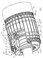
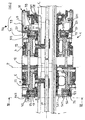
- the assembly drum 1 radially expandable, comprises a body 10 mounted on a central shaft 2 and having a surface 3 for receiving products to be assembled.
- the body 10 comprises two half-cylinders 11 and 13 movable axially around the central shaft 2 in order to adjust the spacing of the bead wires of the tire to be produced, the two half-cylinders 11 and 13 being separated by a fixed central crown 12 axially with respect to the central shaft 2.
- the half-cylinders 11 and 13 as well as the crown 12 are formed by a plurality segments 41, 43 and 42 respectively juxtaposed circumferentially around the central shaft 2, the segments 41, 42 and 43 being aligned.
- each of the segments 41 and 43 is connected to the segment 42 opposite the by means of a rod 14 which crosses the segment 42 and the ends of which are mounted sliding respectively in bores 15 carried by the segments 41 and 43.
- the segments 41, 42, 43 are radially movable under the action of two expansion chambers 17 arranged respectively under said segments 41 and 43, these chambers being inflatable.
- the segments 41 and 43 entail in their radial movement the segments 42 of the crown 12 by means of rods 14.
- Platelets 5 are fixed by screws not shown on the segments 42 of the crown 12. These plates 5 at least partially cover the segments 41 and 43 in order to ensure continuity between the crown 12 and the half-cylinders 11 and 13 for the products to be assembled regardless of the axial position of the half-cylinders.
- the crown 12 also makes it possible to ensure axial retention of the plates 5 during the radial expansion of the drum 1.
- the segments 41 and 43 bear at their lateral ends oriented externally at the drum 1, support elements 6 and 7 respectively carrying receiving grooves 18 and 19 of the tire rods.
- These receiving grooves 18 and 19 have different diameters, the groove 19 having the smallest diameter in this example, which allows the production of an asymmetrical tire, that is to say of which the two beads have different diameters.
- the receiving surface 3 of the products to be assembled is thus constituted by the assembly outer surfaces of the plates 5, areas of segments 41 and 43 not covered by said plates and the external surfaces of the support elements 6 and 7.
- finger means a low profile section.
- the drum 1 chosen in the example described here allows the production of a tire asymmetrical and in which, moreover, the inversion of the carcass reinforcement in each of the beads is disposed between the rod and the carcass reinforcement itself.
- the drum 1 carries at each of the ends of the receiving surface 3, constituted respectively by the external surfaces of the support elements 6 and 7, a lifting device 20.
- a single lifting device will be described below. the one located to the left of plane P in the figures, the second being identical but with a smaller diameter in accordance with that of the groove concerned.
- the lifting device 20 comprises a plurality of lifting fingers 22, of section rectangular, distributed circularly around the central shaft 2 and extending in radial directions.
- These lifting fingers 22 are arranged axially outwardly relative to the center of the drum 1, at the receiving groove 18 at a short distance from the latter and respectively have a support surface 221 of the products to be assembled.
- the fingers 22 are mounted in radial displacement respectively on the segments 41, said fingers 22 being integral with segments 41 in the expansion movement of the drum 1.
- the lifting fingers 22 can be deployed radially outwards from the drum 1 from a rest position in which the bearing surfaces 221 constitute an extension of the receiving surface 3, towards a deployed position in which the bearing surfaces 221 constitute a cylindrical surface coaxial with the central shaft 2, of diameter greater than that of the surface 3.
- These lifting fingers 22 thus offer the products to be assembled a plurality of bearing surfaces 221 discontinuous and distributed circumferentially . In the deployed position, the end zones of the products resting on the bearing surfaces 221 are therefore raised relative to the central part of said products resting on the receiving surface 3.
- the free ends of the lifting fingers 22, that is to say radially external to the drum 1, are constituted by a roller 28 mounted free in rotation about an axis and which thus carries the bearing surface 221.
- This roller 28 allows avoid creating tensions in the products raised during the deployment of lifting fingers 22 ensuring, in this phase, a "rolling" contact between the fingers and products.
- each finger 22 slides inside a groove 60 hollowed out in the support element 6 correspondent. More precisely, the free end of each support element 6, located outside the drum 1 relative to the receiving groove 18, has a U-section cross-sectional view perpendicular to a radius, the branches of the U extending in axial directions.
- This arrangement allows, at the time of installation products whose ends will rest on the bearing surfaces 221, the fingers of lift 22 being at rest, to offer said ends a receiving surface extended all around the surfaces 221. The ends of these products are then also supported by the outer U-shaped surfaces 62 of the ends of the elements support 6, which contributes to obtaining correct positioning on the drum 1 some products.
- each lifting finger 22 carries an axial extension 222.
- Each extension 222 is on a cylinder 23 actuating said finger housed in a bore carried by the segment 41 corresponding.
- the radial displacement of the lifting fingers 22 is limited by the stroke of the actuating cylinders 23 and the axial positioning of said fingers relative to the body 10 is adjustable thanks to the slots 26 carried by the extensions 222 and allowing the passage of fixing screws on the cylinders 23.
- an elastic return belt 27 surrounds all of the axial extensions 222.
- the drum 1 carries retractable means 30 capable of covering the end of the smaller diameter receiving surface, i.e. the end constituted by the support elements 7.
- the retractable means 30 comprise a ferrule 31 whose diameter is substantially identical to that of the outer surfaces plates 5 and which is mounted, so as to be translatable relative to the central shaft 2, between a retracted position shown in Figure 1 and a covering position support elements 7 shown at the top of FIG. 2 relative to the axial plane C. It is clear that the presence of this ferrule 31 makes it possible to install products on a generally cylindrical overall surface so respecting the geometry and the laying tension of said products, we will see later in the description how the retracted position keeps these criteria while having two diameters for the tire beads.
- the ferrule 31 is carried by a support 32 mounted on the central shaft 2.
- the support 32 comprises a first outer ring 33, concentric with the central shaft 2, which covers the ferrule 31 in the retracted position of the latter, the ferrule 31 sliding in the groove 33 formed between the first outer ring 33 and a second inner ring 37.
- the second ring 37 also concentric with the central shaft 2, is disposed at the lateral end of the support 32 oriented towards the body 10, and facilitates the guiding of the ferrule 31.
- the support 32 carries a annular chamber 38 concentric with the central shaft 2 inside which slides axially a piston 381 for actuating the ferrule 31 connected to the latter by connecting rods 39.
- the connection of each connecting rod 39 with the ferrule 31 is achieved by mounting of said connecting rod on a bearing 40 integral with the ferrule 31 and which guides it in translation.
- the drum 1 carries means for expanding the drum 1 towards two separate expanded positions.
- these means of expansion include the expansion chambers 17 described above.
- the expansion means also include two control rings 56 and 57 coaxial with the central shaft 2, rotatably mounted relative to the central shaft 2 axially outside the body of the drum 1 near each of the ends respectively constituted by the segments 6 and 7 of the body 10.
- each of the crowns 56, 57 is further mounted rotatably relative to support rings mounted on the central shaft 2 and integral with the latter.
- the support ring corresponding to the crown 57 consists of the second inner ring 37 which carries, for this purpose, a shoulder internal cylindrical 372 cooperating with the crown 57; crown 56 being mounted on a support ring 36 symmetrically carrying a shoulder 362.
- Each segment 6 (7) carries a pin 63 (73) for engagement in a cam 561 (571) carried by the control crown 56 (57) and, simultaneously, in a light 361 (362) oriented in a radial direction and carried by the support ring 36 (37) as shown in FIG. 3.
- the expanded position accessible to the drum 1 is dependent on the angular position of said crown 56 (57). Indeed, depending on the rotation of the crown 56 (57) and therefore its angular position and that of the cam 561 (571), the pins 63 (73) have a different radial positioning range, which therefore limits the radial expansion of the drum 1, the openings 361 (362) guiding the pins 63 (73) and therefore the segments 41 (43) in radial directions.
- the jack 70 has two chambers delimited by stops 711 and 711 'on the one hand and 713 and 713 'on the other hand.
- the jack 70 also includes a sliding piston 701 bearing a stop end 701 'and a rod 702 sliding inside the piston 701 with an end 702 'which cooperates with the stops 713 and 713'.
- Piston 701 also carries an intermediate stop 712 cooperating with the stop 711, the stop 701 'cooperates with the stop 702'.
- the circumferential position of the crowns 56 and 57 is controlled by actuators 70 and 71 respectively. It is also possible to envisage actuation motorized.
- the method of manufacture of a tire with a radial tourism carcass reinforcement comprising a carcass reinforcement, two beads of different diameters comprising at least a reinforcing rod and in which the carcass reinforcement forms a upturn arranged between the rod and the carcass reinforcement itself.
- the apparatus allowing the implementation of the process, comprises in particular the drum 1 and rod guides 50 movable axially, coaxial with the shaft central 2.
- These rod guides 50 respectively comprise a transfer ring a rod thanks to grippers distributed around its circumference ensuring a hold concentric of the rod with respect to the drum 1.
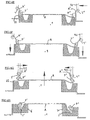
- the guided ferrule 31 is translated thanks to the bearing 40, which covers the support elements 7 and allows the creation of a generally laying surface of the products generally cylindrical.
- a sheet of textile cables is then deposited which, in the example described here, constitutes it alone the carcass reinforcement A, on this overall surface.
- the ferrule 31 is retracted by actuating the connecting rod 39, towards the first ring 33 as shown in Figure 6B. Note in passing that the surface of the shell is chosen and / or treated so that the carcass reinforcement A does not stick to said surface.
- the drum 1 is then passed into the intermediate position as seen on the FIG. 6C, which allows the support elements 7 to come into contact with the end A " of the carcass reinforcement with a slight tension and to have a higher tension of the end A 'deposited on the support elements 6 of larger diameter.
- it is a "braided” type rod, that is to say a rod formed of a core around which are wound one (s) wire (s) or cable (s) on one or several layers likely to rotate around the core.
- the advance of the rod guides 50 is then synchronized with the expansion of the drum 1 towards the expanded position, the rods T 'and T "carrying with it the ends A' and A "of the carcass reinforcement A and making the reversals which take place around profiles P 'and P ", as shown in FIG. 6G.
- This second inflation of the drum 1 is obtained by actuating the jacks 70 and 71 crowns 56 and 57 which rotate them to the extended position of said cylinders corresponding to the representation of FIG. 5E.
- We then supply the rooms expansion 17 which can again deploy since the pins 63 (73) have a new freedom of radial movement until reaching the position shown on the FIG. 5F which corresponds to the expanded position of the drum 1. It is clear that it will suffice relieve the pressure of the expansion chambers 17 and supply the jack 70 (71) with orifice 721 to return the crowns 56 and 57 to their angular position shown in Figure SA to deflate the drum.
- finishing The other constituent products of the tire are then placed.
- the invention does not not concern this part of the manufacturing. Many methods are available at the skilled person; this is why it is useless to approach this aspect of manufacturing in the context of the present invention. Note, however, that in the case of a two-stage manufacturing process, provision must be made for return flanges different diameters on the second drum called "finishing".
- the tire is vulcanized for which the tire is presented pneumatic press with the bead of smaller diameter at the top and we use, to take account of this asymmetry, a press with an upper plate comprising a support crown for molding the upper bead, a device similar, retractable fitted to the lower plate.
- a press with an upper plate comprising a support crown for molding the upper bead
- a device similar, retractable fitted to the lower plate we note, moreover, that the tire is engaged in press and unmolded without difficulty due to the asymmetry.
Landscapes
- Engineering & Computer Science (AREA)
- Mechanical Engineering (AREA)
- Manufacturing & Machinery (AREA)
- Tyre Moulding (AREA)
- Tires In General (AREA)
Applications Claiming Priority (2)
| Application Number | Priority Date | Filing Date | Title |
|---|---|---|---|
| FR9805698 | 1998-04-28 | ||
| FR9805698A FR2777827A1 (fr) | 1998-04-28 | 1998-04-28 | Tambour d'assemblage pour la fabrication de pneumatiques |
Publications (2)
| Publication Number | Publication Date |
|---|---|
| EP0953434A1 EP0953434A1 (fr) | 1999-11-03 |
| EP0953434B1 true EP0953434B1 (fr) | 2003-03-19 |
Family
ID=9526067
Family Applications (1)
| Application Number | Title | Priority Date | Filing Date |
|---|---|---|---|
| EP99107551A Expired - Lifetime EP0953434B1 (fr) | 1998-04-28 | 1999-04-15 | Tambour d'assemblage pour la fabrication de pneumatiques |
Country Status (8)
| Country | Link |
|---|---|
| EP (1) | EP0953434B1 (enExample) |
| JP (1) | JPH11333944A (enExample) |
| KR (1) | KR100559064B1 (enExample) |
| CN (1) | CN1119233C (enExample) |
| BR (1) | BR9901406A (enExample) |
| DE (1) | DE69905965T2 (enExample) |
| ES (1) | ES2193616T3 (enExample) |
| FR (1) | FR2777827A1 (enExample) |
Cited By (1)
| Publication number | Priority date | Publication date | Assignee | Title |
|---|---|---|---|---|
| US10946602B2 (en) * | 2015-11-25 | 2021-03-16 | Compagnie Generale Des Etablissements Michelin | Drum and method for assembling an adapter for mounting a tire on a wheel rim |
Families Citing this family (8)
| Publication number | Priority date | Publication date | Assignee | Title |
|---|---|---|---|---|
| US6506274B1 (en) | 1998-07-23 | 2003-01-14 | Michelin Recherche Et Technique, S.A. | Apparatus and method for manufacture of tires |
| AU2002215974A1 (en) | 2000-10-27 | 2002-05-06 | Michelin Recherche Et Technique S.A. | Tyre building drum |
| DE60219514T2 (de) * | 2001-11-28 | 2008-01-03 | Bridgestone Corp. | Reifenherstellungsverfahren und reifenformmaschine |
| JP4495912B2 (ja) * | 2003-01-14 | 2010-07-07 | 三菱樹脂株式会社 | 多層フィルムおよび容器 |
| DE102005044231A1 (de) * | 2005-09-16 | 2007-03-29 | Continental Aktiengesellschaft | Verfahren zur Herstellung von Fahrzeugluftreifen mit geklemmtem Lagenumschlag |
| US9360396B2 (en) * | 2011-10-06 | 2016-06-07 | Kobe Steel, Ltd. | Tire uniformity testing device and tire uniformity testing method |
| FR3066430B1 (fr) * | 2017-05-22 | 2020-10-30 | Michelin & Cie | Tambour et procede d'assemblage d'un adaptateur de pneumatique sur une jante |
| JP6993874B2 (ja) * | 2017-12-28 | 2022-01-14 | Toyo Tire株式会社 | シート部材の巻き取り方法及び巻き取り筒 |
Family Cites Families (5)
| Publication number | Priority date | Publication date | Assignee | Title |
|---|---|---|---|---|
| US2045545A (en) * | 1933-10-30 | 1936-06-23 | Nat Standard Co | Process and apparatus for making drum built tires |
| US2440662A (en) * | 1945-10-31 | 1948-04-27 | Nat Standard Co | Apparatus for building tires |
| DE1198054B (de) * | 1964-03-06 | 1965-08-05 | Continental Gummi Werke Ag | Aufbauvorrichtung fuer Rollbalgrohlinge, Reifenrohlinge oder aehnlich aufgebaute Hohlkoerperrohlinge |
| JPH04153028A (ja) * | 1990-10-18 | 1992-05-26 | Bridgestone Corp | グリーンケース及びグリーンタイヤの製造方法 |
| JPH10180901A (ja) * | 1996-12-25 | 1998-07-07 | Yokohama Rubber Co Ltd:The | 空気入りタイヤ及びその製造方法 |
-
1998
- 1998-04-28 FR FR9805698A patent/FR2777827A1/fr active Pending
-
1999
- 1999-04-15 EP EP99107551A patent/EP0953434B1/fr not_active Expired - Lifetime
- 1999-04-15 ES ES99107551T patent/ES2193616T3/es not_active Expired - Lifetime
- 1999-04-15 DE DE69905965T patent/DE69905965T2/de not_active Expired - Fee Related
- 1999-04-26 BR BR9901406A patent/BR9901406A/pt not_active Application Discontinuation
- 1999-04-28 KR KR1019990015184A patent/KR100559064B1/ko not_active Expired - Fee Related
- 1999-04-28 CN CN99106134A patent/CN1119233C/zh not_active Expired - Fee Related
- 1999-04-28 JP JP11121464A patent/JPH11333944A/ja not_active Ceased
Cited By (1)
| Publication number | Priority date | Publication date | Assignee | Title |
|---|---|---|---|---|
| US10946602B2 (en) * | 2015-11-25 | 2021-03-16 | Compagnie Generale Des Etablissements Michelin | Drum and method for assembling an adapter for mounting a tire on a wheel rim |
Also Published As
| Publication number | Publication date |
|---|---|
| KR100559064B1 (ko) | 2006-03-10 |
| DE69905965D1 (de) | 2003-04-24 |
| ES2193616T3 (es) | 2003-11-01 |
| JPH11333944A (ja) | 1999-12-07 |
| CN1119233C (zh) | 2003-08-27 |
| KR19990083560A (ko) | 1999-11-25 |
| DE69905965T2 (de) | 2003-11-27 |
| BR9901406A (pt) | 2000-03-21 |
| CN1233554A (zh) | 1999-11-03 |
| EP0953434A1 (fr) | 1999-11-03 |
| FR2777827A1 (fr) | 1999-10-29 |
Similar Documents
| Publication | Publication Date | Title |
|---|---|---|
| EP0906186B1 (fr) | Tambour d'assemblage d'un pneumatique | |
| EP0953434B1 (fr) | Tambour d'assemblage pour la fabrication de pneumatiques | |
| EP0953435B1 (fr) | Procédé de fabrication de pneumatiques et tambour d'assemblage permettant la mise en oeuvre du procédé | |
| EP0718090B1 (fr) | Tambour d'assemblage de pneumatique | |
| EP0974448B1 (fr) | Appareillage et procédé de fabrication de pneumatiques | |
| EP3380312B1 (fr) | Tambour et procede d'assemblage d'un adaptateur de pneumatique sur une jante | |
| EP1347875B1 (fr) | Tambour d'assemblage pour la fabrication de pneumatiques | |
| EP0637505B1 (fr) | Procédé et machine de confection de pneumatiques | |
| FR2467685A1 (fr) | Appareil a confectionner des pneumatiques | |
| US20030024626A1 (en) | Method and apparatus for tire carcass positioning on a drum | |
| EP2032350B1 (en) | Process and apparatus for manufacturing a pneumatic tyre | |
| EP0976532B1 (fr) | Moule pour pneumatique de véhicule, et presse de vulcanisation adaptée pour recevoir un tel moule | |
| EP1347874B1 (fr) | Tambour d'assemblage pour la fabrication de pneumatiques | |
| EP0813951B1 (fr) | Anneau de transfert d'une enveloppe de pneumatique ou d'une ceinture d'enveloppe de pneumatique | |
| FR3022834A1 (fr) | Tambour de confection d'une ebauche d'enveloppe de pneumatique avec des secteurs cylindriques telescopiques | |
| EP3390030A1 (fr) | Tambour de confection et de conformation d'une carcasse de pneumatique | |
| EP1623820B1 (fr) | Dispositif d'enroulage d'un manchon cylindrique autour d'un anneau torique | |
| JP2001038821A (ja) | タイヤの製造装置およびタイヤの製造方法 | |
| EP4126521A1 (fr) | Tambour de confection d'un adaptateur de pneumatique sur une jante | |
| FR2579134A1 (fr) | Dispositif d'avance des elements constitutifs annulaires de pneumatiques vers un tambour de confection |
Legal Events
| Date | Code | Title | Description |
|---|---|---|---|
| PUAI | Public reference made under article 153(3) epc to a published international application that has entered the european phase |
Free format text: ORIGINAL CODE: 0009012 |
|
| AK | Designated contracting states |
Kind code of ref document: A1 Designated state(s): BE CH DE ES FR GB IT LI LU NL |
|
| AX | Request for extension of the european patent |
Free format text: AL;LT;LV;MK;RO;SI |
|
| 17P | Request for examination filed |
Effective date: 20000503 |
|
| AKX | Designation fees paid |
Free format text: BE CH DE ES FR GB IT LI LU NL |
|
| 17Q | First examination report despatched |
Effective date: 20010928 |
|
| GRAG | Despatch of communication of intention to grant |
Free format text: ORIGINAL CODE: EPIDOS AGRA |
|
| RAP1 | Party data changed (applicant data changed or rights of an application transferred) |
Owner name: COMPAGNIE GENERALE DES ETABLISSEMENTS MICHELIN-MIC |
|
| GRAG | Despatch of communication of intention to grant |
Free format text: ORIGINAL CODE: EPIDOS AGRA |
|
| GRAH | Despatch of communication of intention to grant a patent |
Free format text: ORIGINAL CODE: EPIDOS IGRA |
|
| GRAH | Despatch of communication of intention to grant a patent |
Free format text: ORIGINAL CODE: EPIDOS IGRA |
|
| GRAA | (expected) grant |
Free format text: ORIGINAL CODE: 0009210 |
|
| AK | Designated contracting states |
Designated state(s): BE CH DE ES FR GB IT LI LU NL |
|
| REG | Reference to a national code |
Ref country code: GB Ref legal event code: FG4D Free format text: NOT ENGLISH |
|
| REG | Reference to a national code |
Ref country code: CH Ref legal event code: EP |
|
| REF | Corresponds to: |
Ref document number: 69905965 Country of ref document: DE Date of ref document: 20030424 Kind code of ref document: P |
|
| GBT | Gb: translation of ep patent filed (gb section 77(6)(a)/1977) | ||
| REG | Reference to a national code |
Ref country code: ES Ref legal event code: FG2A Ref document number: 2193616 Country of ref document: ES Kind code of ref document: T3 |
|
| PLBE | No opposition filed within time limit |
Free format text: ORIGINAL CODE: 0009261 |
|
| STAA | Information on the status of an ep patent application or granted ep patent |
Free format text: STATUS: NO OPPOSITION FILED WITHIN TIME LIMIT |
|
| 26N | No opposition filed |
Effective date: 20031222 |
|
| PGFP | Annual fee paid to national office [announced via postgrant information from national office to epo] |
Ref country code: NL Payment date: 20060413 Year of fee payment: 8 |
|
| PGFP | Annual fee paid to national office [announced via postgrant information from national office to epo] |
Ref country code: LU Payment date: 20060414 Year of fee payment: 8 |
|
| PGFP | Annual fee paid to national office [announced via postgrant information from national office to epo] |
Ref country code: CH Payment date: 20060418 Year of fee payment: 8 |
|
| PGFP | Annual fee paid to national office [announced via postgrant information from national office to epo] |
Ref country code: GB Payment date: 20060420 Year of fee payment: 8 |
|
| PGFP | Annual fee paid to national office [announced via postgrant information from national office to epo] |
Ref country code: ES Payment date: 20060427 Year of fee payment: 8 |
|
| PGFP | Annual fee paid to national office [announced via postgrant information from national office to epo] |
Ref country code: BE Payment date: 20060502 Year of fee payment: 8 |
|
| REG | Reference to a national code |
Ref country code: CH Ref legal event code: PL |
|
| GBPC | Gb: european patent ceased through non-payment of renewal fee |
Effective date: 20070415 |
|
| BERE | Be: lapsed |
Owner name: CIE GENERALE DES ETS *MICHELIN-MICHELIN & CIE Effective date: 20070430 |
|
| NLV4 | Nl: lapsed or anulled due to non-payment of the annual fee |
Effective date: 20071101 |
|
| PG25 | Lapsed in a contracting state [announced via postgrant information from national office to epo] |
Ref country code: NL Free format text: LAPSE BECAUSE OF NON-PAYMENT OF DUE FEES Effective date: 20071101 |
|
| PG25 | Lapsed in a contracting state [announced via postgrant information from national office to epo] |
Ref country code: LI Free format text: LAPSE BECAUSE OF NON-PAYMENT OF DUE FEES Effective date: 20070430 Ref country code: CH Free format text: LAPSE BECAUSE OF NON-PAYMENT OF DUE FEES Effective date: 20070430 |
|
| PG25 | Lapsed in a contracting state [announced via postgrant information from national office to epo] |
Ref country code: BE Free format text: LAPSE BECAUSE OF NON-PAYMENT OF DUE FEES Effective date: 20070430 |
|
| PG25 | Lapsed in a contracting state [announced via postgrant information from national office to epo] |
Ref country code: GB Free format text: LAPSE BECAUSE OF NON-PAYMENT OF DUE FEES Effective date: 20070415 |
|
| REG | Reference to a national code |
Ref country code: ES Ref legal event code: FD2A Effective date: 20070416 |
|
| PGFP | Annual fee paid to national office [announced via postgrant information from national office to epo] |
Ref country code: DE Payment date: 20080418 Year of fee payment: 10 |
|
| PGFP | Annual fee paid to national office [announced via postgrant information from national office to epo] |
Ref country code: IT Payment date: 20080424 Year of fee payment: 10 |
|
| PG25 | Lapsed in a contracting state [announced via postgrant information from national office to epo] |
Ref country code: ES Free format text: LAPSE BECAUSE OF NON-PAYMENT OF DUE FEES Effective date: 20070416 |
|
| PGFP | Annual fee paid to national office [announced via postgrant information from national office to epo] |
Ref country code: FR Payment date: 20080412 Year of fee payment: 10 |
|
| PG25 | Lapsed in a contracting state [announced via postgrant information from national office to epo] |
Ref country code: LU Free format text: LAPSE BECAUSE OF NON-PAYMENT OF DUE FEES Effective date: 20070415 |
|
| REG | Reference to a national code |
Ref country code: FR Ref legal event code: ST Effective date: 20091231 |
|
| PG25 | Lapsed in a contracting state [announced via postgrant information from national office to epo] |
Ref country code: DE Free format text: LAPSE BECAUSE OF NON-PAYMENT OF DUE FEES Effective date: 20091103 |
|
| PG25 | Lapsed in a contracting state [announced via postgrant information from national office to epo] |
Ref country code: FR Free format text: LAPSE BECAUSE OF NON-PAYMENT OF DUE FEES Effective date: 20091222 |
|
| PG25 | Lapsed in a contracting state [announced via postgrant information from national office to epo] |
Ref country code: IT Free format text: LAPSE BECAUSE OF NON-PAYMENT OF DUE FEES Effective date: 20090415 |