EP0976532B1 - Moule pour pneumatique de véhicule, et presse de vulcanisation adaptée pour recevoir un tel moule - Google Patents
Moule pour pneumatique de véhicule, et presse de vulcanisation adaptée pour recevoir un tel moule Download PDFInfo
- Publication number
- EP0976532B1 EP0976532B1 EP99112910A EP99112910A EP0976532B1 EP 0976532 B1 EP0976532 B1 EP 0976532B1 EP 99112910 A EP99112910 A EP 99112910A EP 99112910 A EP99112910 A EP 99112910A EP 0976532 B1 EP0976532 B1 EP 0976532B1
- Authority
- EP
- European Patent Office
- Prior art keywords
- segments
- mould
- diameter
- tyre
- bead
- Prior art date
- Legal status (The legal status is an assumption and is not a legal conclusion. Google has not performed a legal analysis and makes no representation as to the accuracy of the status listed.)
- Expired - Lifetime
Links
- 238000004073 vulcanization Methods 0.000 title description 20
- 238000000465 moulding Methods 0.000 claims description 86
- 239000011324 bead Substances 0.000 claims description 62
- 239000012528 membrane Substances 0.000 claims description 46
- 230000000295 complement effect Effects 0.000 claims description 2
- 238000000034 method Methods 0.000 description 3
- 238000010276 construction Methods 0.000 description 1
- 230000001627 detrimental effect Effects 0.000 description 1
- 238000006073 displacement reaction Methods 0.000 description 1
- 230000002349 favourable effect Effects 0.000 description 1
- 239000012530 fluid Substances 0.000 description 1
- 230000003100 immobilizing effect Effects 0.000 description 1
- 238000009434 installation Methods 0.000 description 1
- 238000004519 manufacturing process Methods 0.000 description 1
Images


Classifications
-
- B—PERFORMING OPERATIONS; TRANSPORTING
- B29—WORKING OF PLASTICS; WORKING OF SUBSTANCES IN A PLASTIC STATE IN GENERAL
- B29C—SHAPING OR JOINING OF PLASTICS; SHAPING OF MATERIAL IN A PLASTIC STATE, NOT OTHERWISE PROVIDED FOR; AFTER-TREATMENT OF THE SHAPED PRODUCTS, e.g. REPAIRING
- B29C35/00—Heating, cooling or curing, e.g. crosslinking or vulcanising; Apparatus therefor
- B29C35/02—Heating or curing, e.g. crosslinking or vulcanizing during moulding, e.g. in a mould
-
- B—PERFORMING OPERATIONS; TRANSPORTING
- B29—WORKING OF PLASTICS; WORKING OF SUBSTANCES IN A PLASTIC STATE IN GENERAL
- B29D—PRODUCING PARTICULAR ARTICLES FROM PLASTICS OR FROM SUBSTANCES IN A PLASTIC STATE
- B29D30/00—Producing pneumatic or solid tyres or parts thereof
- B29D30/06—Pneumatic tyres or parts thereof (e.g. produced by casting, moulding, compression moulding, injection moulding, centrifugal casting)
- B29D30/0601—Vulcanising tyres; Vulcanising presses for tyres
- B29D30/0606—Vulcanising moulds not integral with vulcanising presses
- B29D30/0629—Vulcanising moulds not integral with vulcanising presses with radially movable sectors
-
- B—PERFORMING OPERATIONS; TRANSPORTING
- B29—WORKING OF PLASTICS; WORKING OF SUBSTANCES IN A PLASTIC STATE IN GENERAL
- B29D—PRODUCING PARTICULAR ARTICLES FROM PLASTICS OR FROM SUBSTANCES IN A PLASTIC STATE
- B29D30/00—Producing pneumatic or solid tyres or parts thereof
- B29D30/06—Pneumatic tyres or parts thereof (e.g. produced by casting, moulding, compression moulding, injection moulding, centrifugal casting)
- B29D30/0601—Vulcanising tyres; Vulcanising presses for tyres
- B29D30/0606—Vulcanising moulds not integral with vulcanising presses
- B29D2030/0607—Constructional features of the moulds
- B29D2030/062—Means for sealing the tyre against the mould in the bead areas
- B29D2030/0621—Means for sealing the tyre against the mould in the bead areas to seal the bead portions against the mould i.e. by using pressing devices
- B29D2030/0622—Means for sealing the tyre against the mould in the bead areas to seal the bead portions against the mould i.e. by using pressing devices the pressing devices being collapsable, e.g. annular elements consisting of a plurality of sectors
Definitions
- the present invention relates to the molding of tires.
- it concerns the molding of a tire comprising beads of particular shape, requiring the molding of an undercut part in the axially and radially inner zone of the bead.
- Rings for molding the radially and axially inner part of a bead have have also been described in connection with the so-called vulcanization processes without membrane.
- the cited patent above describes a mechanism occupying the entire interior volume of the press, in order to ability to give the different segments of the ring the necessary movements so that these segments can have a closing or opening movement in sequence.
- sequential movement means that, from a configuration where the mold is open, the not all segments come to their molding position at the same time.
- a first group is brought to its final molding position, then the segments of a second group are inserted between each of the segments of the first group, in order to produce a continuous ring.
- the object of the present invention is to provide a means for molding, on the beads of a tire, undercut zones in the direction given above to this expression, without excessively increasing the cost of a tire mold.
- the invention starts from the reflection that, if the diameters of the beads of the tire are sufficiently different, it is possible to use on one side a continuous counter-molding ring, that is to say in one piece. Indeed, the bead of larger diameter can pass through above the ring of countermolding of the bead of smaller diameter without requiring any deformation. This is favorable to the good quality of the molding and to the economy of the process. It is indeed difficult, and detrimental to the quality of the tire, to cause deformations in vintage tire tread.
- the invention makes it possible to avoid any deformation by ovalization at raw draft stage, or at least allows them to be drastically reduced. Indeed, at this point, raw rubber does not yet have sufficient mechanical strength to allow it to easily withstand phases of deformation by ovalization, and manipulations to cross a continuous rigid ring, the outside diameter of which is greater than the diameter inside of the beads to be vulcanized.
- the invention also proposes to combine the use of counter-molding rings, one of which is continuous and the other is divided, with the use of a flexible membrane to mold the part of the internal cavity of the tire between the counter-molding rings.
- the character asymmetrical of the mold thus proposed makes it easier to accommodate inside the press the mechanism required to control the counter-molding ring divided into several segments and the mechanism necessary for the movement of the vulcanization membrane.
- the mold according to the invention for a tire comprising a tread, two sidewalls and two beads is defined in claim 1.
- the mold comprises a divided counter-molding ring for molding the bead of larger diameter from said radially inner limit where the diameter of the surface of the tire is ⁇ 2 to an axially inner limit of diameter ⁇ 3 , said divided ring comprising a plurality of retractable segments, adjacent in the molding position.
- the mold according to the invention comprises a flexible membrane for molding the internal surface of the tire in the part of the internal cavity of the tire comprised between the diameter limit ⁇ 1 and the diameter limit ⁇ 3 .
- any suitable type of mold can be used for the part molding the outer surface of the tire beyond the beads.
- the shells used ensure the molding of the sidewalls alone, while a set of radially movable sectors is used to mold the tread.
- a person skilled in the art will have recognized a sector mold.
- the invention proposes the means of molding the interior surface of the tire going down to the beads. including at least partially the radially inner part of the beads. This is especially useful when said surface has a particular shape, in particular undercut with respect to a reference direction parallel to the axis.
- the molding of the outer surface of the tire is not the subject of the present invention. We may use any technique which may prove appropriate.
- the invention also provides a vulcanization press for tires, comprising a mechanism for conferring on a multi-piece counter molding ring all movements required without adding an additional command to those normally available on a vulcanization press.
- the invention provides a membrane type press, arranged and adapted so that the movement of the lower diaphragm plate relative to the frame lower suffices to also control the movement of all segments of the ring against molding.
- the press according to the invention which receives a tire mold having an axis corresponding to the axis of rotation of said tire is defined in claim 6.
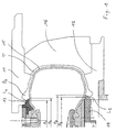
- the counter-molding rings are therefore intended to mold the part of each of the beads B1 and B2 lying between the limits respectively L1 and L2 and until a shape compatible with molding is found using a flexible membrane. deployable inside the internal cavity of the tire.
- the continuous counter-molding ring 13 provides molding between the limit L1 corresponding to the diameter ⁇ 0 and the level of the interior surface of the tire where the diameter has the value ⁇ 1 .
- the value of the diameter ⁇ 1 is less than or equal to the diameter ⁇ 2 corresponding to the limit L2 of the bead B2 of larger diameter. Therefore, without any other particular measure, it is possible to pass the continuous counter-molding ring 13 through the interior of the opposite bead B2. This continuous counter-molding ring 13 is produced in one piece.
- the divided counter-molding ring 14 is produced in several segments: the first segments 141 and the second segments 142. This makes it possible to retract the divided counter-molding ring 14 so as to be able to introduce the tire into the vulcanization press and in order to be able to extract the tire after vulcanization.
- N 3
- N 3
- N 3
- N 3
- N 3
- N 3
- a membrane 15 is used for the rest of the interior cavity of the tire. vulcanization, because membrane vulcanization is a well proven and reliable technique. We also sees that one uses a mold with sectors 16 movable relative to the shells, for molding the outer surface of the tread.
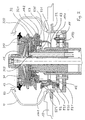
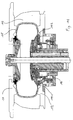
- FIG 2 we see a press having a lower frame 22 on which is fixed the shell 12.
- the press also includes a movable frame (not shown) also called upper frame, on which is fixed the shell 11.
- a movable frame also called upper frame, on which is fixed the shell 11.
- the adjectives "Lower” and "upper” we designate certain parts of the press by the adjectives "Lower” and "upper” to use the usual terminology because the presses are in general built to receive a mold positioned with vertical axis.
- the inferior or superior character of the elements of the press is not limiting and the terms are not used only so as not to disturb the reader with terminology which is not usual.
- the press described uses a symmetrical membrane 15, without the symmetrical nature of the membrane is limiting.
- the membrane 15 is anchored on a lower membrane plate 32 and on an upper membrane plate 31.
- the movements imparted to the lower membrane plate 32 and the upper membrane plate 31 are well known. They allow or facilitate the deployment of the membrane or its folding at the time of demolding, the loading of a raw tire to be vulcanized, unloading of a tire after vulcanization.
- a loading bracket 60 used to deposit a raw bandage on the shell 12.
- the continuous counter-molding ring 13 is mounted directly on the membrane plate upper 31.
- said upper diaphragm plate 31 has a mounting surface 310 to receive said continuous counter-molding ring 13. This is therefore and necessarily driven by the same movements as the upper diaphragm plate 31.
- the continuous ring of against molding 13 is thus easily removable, to adapt to the profile that we want to mold on the corresponding bead of the tire.
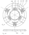
- first 141 and second 142 segments together constituting the ring ten counter molding 14.
- the second segments 142 are inserted between the first segments and after their final positioning, as a keystone is inserted in the final phase of the construction of an arc, to complete the constitution of the ring 14.
- the continuous ring of counter molding 13 ensures the molding of part of the small diameter bead, that is to say of the said upper bead, with reference to its position in the press.
- the Split Ring against molding 14 ensures the molding of part of the large diameter bead, that is to say of the said lower bead, with reference to its position in the press.
- Each of the first segments 141 is mounted on a tilting arm 52, itself rotatably mounted at point 520 on a slide 17.
- the slide 17 is mounted on the lower frame 12 of the press, and can be translated from it over a short distance, the movement of translation being parallel to the axis.
- the role of this axial translation will appear in the following. of the springs 170 tend to push the slide 17 against a stop 171, its rest position being against the stop 171, as in FIG. 2.
- a spring 525 (for each of the rocking arms 52) pushes each tilting arm 52 towards an open position (or retracted position) such that it is shown in Figure 3.
- a roller 521 is rotatably mounted on each of the rocking arms 52.
- a first cam 42 is integral with the lower diaphragm plate 32.
- the profile of the radially outer surface of this first cam 42 will make it possible to define a law judicious for the rocking movement of the rocking arms 52.
- the first cam 42 has a ramp, or conical bearing, followed by a cylindrical bearing.
- the arm device tilting 52, rollers 521 and springs 525 constitutes a first cam follower, actuating the first segments 141.
- the means for receiving the first segments are a range of 522 mounting on each of the rocking arms, which allows very easily the exchange of the first segments 141 according to the profile to be molded on the tire to be manufactured.
- a counter plate 320 immobilizing the membrane 15 on the membrane plate lower 32 is mounted on a hollow rod provided with pipes 329 for supplying and extracting the vulcanization fluid from inside the membrane 15.
- a guide plate 321 mounted on the lower membrane plate 32 is mounted on the lower membrane plate 32.
- the second segments 142 are mounted on the guide plate 321, in slides 53 arranged between said guide plate 321 and the first cam 42. Said second segments 142 are thus guided relative to the lower membrane plate 32.
- a spring 535 (for each second segments 142) pushes each second segment 142 towards an open position (or radially retracted position or even retracted position) as shown in the Figure 3.
- a roller 531 is rotatably mounted on each of the second segments 142.
- the group of second segment is very easily interchangeable according to the profile to be molded on the tire to manufacture. Just mount a roller 531 on each second segment 142 and insert a spring 535 during the installation of each second segment 142, which constitutes the means for receive the second segments 142.
- a second cam 43 is fixed to the lower frame 22 of the press.
- the profile of the surface radially exterior of this second cam 43 will make it possible to define a judicious law for monitor the progress of the second segments 142.
- the second cam here has a ramp, or conical bearing, followed by a cylindrical bearing.
- the roller device 531 and springs 535 constitutes a second cam follower, actuating the second segments 142.
- the different phases of the molding movement are as follows.
- the molding of the beads B1 and B2 by the counter-molding rings 13 and 14 respectively can be simultaneous.
- the deployment of the membrane 15 occurs from preferably after the molding of the beads by the counter-molding rings, which has just been explained above.
- the press is then in the configuration of Figure 10.
- the pursuit vulcanization is classic.
- the membrane 15 is folded back.
- the split ring is retracted against molding 14, by a relative spacing of the lower membrane plate 32 relative to the frame lower 22 (which in reverse causes all of the movements explained above).
- the continuous ring is axially separated from against molding 13 relative to the shell 11, which makes it possible to insert a clamp of unloading under the bead B1.
- the divided ring of countermolding is arranged in an alternate arrangement where the first segments are linked to the lower press frame while the second segments are linked to lower membrane tray.
- the invention allows an embodiment of great compactness, which maintains an internal mechanism necessary for the deployment of the flexible membrane vulcanization. It also allows you to get all the movements you want without any command other than that of the lower and upper membrane plates.
- the movable press frame with control means making it possible to mold using a multi-piece counter molding ring.
- the invention makes it possible to mold specifies the beads of those of tires whose bead has a shape special.
- the invention makes it possible to reconcile the molding of complex shapes with a relative simplicity of the mold and the vulcanization press.
- the vulcanization press does not has no additional motion controls compared to movement already existing in completely conventional vulcanization membrane presses.
Landscapes
- Physics & Mathematics (AREA)
- Health & Medical Sciences (AREA)
- Oral & Maxillofacial Surgery (AREA)
- Thermal Sciences (AREA)
- Engineering & Computer Science (AREA)
- Mechanical Engineering (AREA)
- Moulds For Moulding Plastics Or The Like (AREA)
- Heating, Cooling, Or Curing Plastics Or The Like In General (AREA)
Description
- à la figure 1, un moule pour pneumatique selon l'invention.
- à la figure 2, une presse de vulcanisation selon l'invention dans la configuration apparaissant lors du chargement d'un bandage cru,
- aux figures 3 et 4, l'anneau divisé de contre moulage, dans la configuration apparaissant lors du chargement d'un bandage cru.
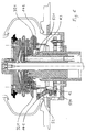
- à la figure 5, la même presse dans une première phase de sa fermeture,
- aux figures 6 et 7, l'anneau divisé de contre moulage, dans la configuration correspondant à la figure 5,
- à la figure 8, la même presse dans phase ultérieure de sa fermeture,
- aux figures 9 et 10, l'anneau divisé de contre moulage, dans la configuration correspondant à la figure 8,
- et enfin à la figure 11, la même presse en position de moulage.
Claims (11)
- Moule pour pneumatique (T) comportant une bande de roulement, deux flancs et deux bourrelets (B1, B2), Φ0 étant le diamètre minimal de la surface du pneumatique au bourrelet, ledit moule comportant :ledit moule étant caractérisé en ce quedeux coquilles (11, 12) pour mouler respectivement la surface extérieure de chacun des flancs et pour mouler la partie extérieure de chacun des bourrelets jusqu'à une limite radialement intérieure où le diamètre de la surface du pneumatique est minimal,un anneau continu de contre-moulage (13) pour mouler l'un des bourrelet depuis ladite limite radialement intérieure où le diamètre de la surface du pneumatique est Φ0 jusqu'à une limite axialement intérieure de diamètre Φ1, avec Φ 1 plus grand que Φ0,les deux flancs et les deux bourrelets sont non symétriques, Φ0 étant le diamètre minimal de la surface du pneumatique au bourrelet de plus petit diamètre, Φ2 étant le diamètre minimal de la surface du pneumatique au bourrelet de plus grand diamètre,l'anneau continu de contre-moulage (13) est destiné à mouler le bourrelet de plus petit diamètre etΦ 1 est plus petit que Φ2.
- Moule selon la revendication 1, comprenant un anneau divisé de contre-moulage (14) pour mouler le bourrelet de plus grand diamètre depuis ladite limite radialement intérieure où le diamètre de la surface du pneumatique est Φ2 jusqu'à une limite axialement intérieure de diamètre Φ3, ledit anneau divisé comportant une pluralité de segments (141, 142) escamotables, adjacents en position de moulage.
- Moule selon la revendication 1 ou 2, comprenant une membrane flexible (15) pour mouler la surface intérieure du pneumatique dans la partie de la cavité interne du pneumatique comprise entre la limite de diamètre Φ1 et la limite de diamètre Φ3.
- Moule selon l'une des revendications 1 à 3, dans lequel la pluralité de segments escamotables comporte un nombre N de premiers segments (141) dont les faces latérales, circonférentiellement, sont convergentes à l'intérieur du moule, et comporte le même nombre N de seconds segments (142) complémentaires auxdits premiers segments.
- Moule selon l'une des revendications 1 à 4, comportant des secteurs (16) mobiles par rapport aux coquilles, pour mouler la surface extérieure de la bande de roulement.
- Presse de vulcanisation de pneumatiques, recevant un moule pour pneumatique ayant un axe correspondant à l'axe de rotation dudit pneumatique, ledit moule comportant :ladite presse comportant :deux coquilles (11, 12) pour mouler la surface extérieure d'un flanc et pour mouler la partie extérieure d'un des bourrelets jusqu'à une limite radialement intérieure où le diamètre de la surface du pneumatique est minimal,au moins un anneau divisé de contre moulage (14) pour mouler la surface d'un bourrelet au-delà de ladite limite et du côté axialement intérieur, ledit anneau divisé de contre-moulage étant constitué par des premiers segments (141) et des seconds segments (142), lesdits premiers et seconds segment étant adjacents en position de moulage,caractérisée en ce queun bâti inférieur (22) pour recevoir l'une des coquilles,un bâti mobile pour recevoir l'autre coquille,des moyens de commande du rapprochement et de l'éloignement relatifs desdits bâti inférieur et bâti mobile,des premiers moyens pour recevoir les premiers segments et des seconds moyens pour recevoir les seconds segments, l'ensemble des premiers et seconds segments formant ledit anneau divisé de contre-moulage,un mécanisme de déplacement des premiers et seconds segments, ledit mécanisme de déplacement assurant le mouvement en séquences successives des premiers segments dans une première séquence, et des seconds segments dans une seconde séquence, de façon à amener en position de moulage et à escamoter lesdits segments de l'anneau de contre-moulage,le moule comporte une membrane (15) de moulage de l'intérieur du pneumatique,ladite presse comporte un plateau-membrane inférieur (32) et des moyens de commande du mouvement relatif entre le plateau-membrane inférieur et le bâti inférieur (22) etle mécanisme de déplacement est actionné par le mouvement relatif du plateau-membrane inférieur par rapport au bâti inférieur.
- Presse selon la revendication 6, dans laquelle les premiers segments (141) sont liés au bâti inférieur (22) et les seconds segments (142) sont liés au plateau-membrane inférieur (32).
- Presse selon la revendication 6 ou 7, dans laquelle le mécanisme de déplacement comprend :une première came (42) solidaire du plateau-membrane inférieur (32) et des premiers suiveurs de came actionnant les premiers segments,une seconde came (43) solidaire du bâti inférieur et des seconds suiveurs de came actionnant les seconds segments.
- Presse selon la revendication 8, dans laquelle les premiers suiveurs de came sont des bras basculants (52), un galet (521) étant monté rotatif sur chacun desdits bras articulés et coopérant avec ladite première came (42).
- Presse selon l'une des revendications 5 à 9, dans laquelle les premiers segments (141) sont montés sur un coulisseau (17) translatable par rapport au bâti inférieur (22), le mouvement de translation étant parallèle à l'axe.
- Presse selon l'une des revendications 6 à 10, comportant un plateau-membrane supérieur (31) coulissant par rapport au plateau-membrane inférieur (32) , ledit plateau-membrane supérieur comportant des moyens d'ancrage pour ladite membrane de vulcanisation (15), ledit plateau-membrane supérieur comportant une portée de montage (310) pour recevoir un anneau continu de contre-moulage de la surface radialement et axialement intérieure d'un bourrelet.
Applications Claiming Priority (2)
| Application Number | Priority Date | Filing Date | Title |
|---|---|---|---|
| FR9809593A FR2781411A1 (fr) | 1998-07-23 | 1998-07-23 | Moule pour pneumatique de vehicule, et presse de vulcanisation adaptee pour recevoir un tel moule |
| FR9809593 | 1998-07-23 |
Publications (2)
| Publication Number | Publication Date |
|---|---|
| EP0976532A1 EP0976532A1 (fr) | 2000-02-02 |
| EP0976532B1 true EP0976532B1 (fr) | 2003-04-09 |
Family
ID=9529069
Family Applications (1)
| Application Number | Title | Priority Date | Filing Date |
|---|---|---|---|
| EP99112910A Expired - Lifetime EP0976532B1 (fr) | 1998-07-23 | 1999-07-05 | Moule pour pneumatique de véhicule, et presse de vulcanisation adaptée pour recevoir un tel moule |
Country Status (11)
| Country | Link |
|---|---|
| EP (1) | EP0976532B1 (fr) |
| JP (1) | JP2000043050A (fr) |
| KR (1) | KR100571296B1 (fr) |
| CN (1) | CN1154557C (fr) |
| BR (1) | BR9902982A (fr) |
| CA (1) | CA2277702A1 (fr) |
| DE (1) | DE69906638T2 (fr) |
| ES (1) | ES2196677T3 (fr) |
| FR (1) | FR2781411A1 (fr) |
| PL (1) | PL189743B1 (fr) |
| RU (1) | RU2220045C2 (fr) |
Families Citing this family (7)
| Publication number | Priority date | Publication date | Assignee | Title |
|---|---|---|---|---|
| KR20030050422A (ko) * | 2001-12-18 | 2003-06-25 | 한국타이어 주식회사 | 타이어용 가류금형 |
| US6854963B2 (en) * | 2002-01-28 | 2005-02-15 | The Goodyear Tire & Rubber Company | Radially expandable bead molding ring for a tire mold |
| US7278455B2 (en) * | 2004-12-20 | 2007-10-09 | The Goodyear Tire & Rubber Company | Asymmetrical pneumatic run-flat tire |
| WO2008068551A1 (fr) * | 2006-12-06 | 2008-06-12 | Pirelli Tyre S.P.A. | Procédé et appareil de fabrication de pneus |
| EP2318203B1 (fr) | 2008-08-04 | 2013-12-25 | Pirelli Tyre S.P.A. | Procédé et appareil de moulage et de vulcanisation de pneus |
| JP5631904B2 (ja) * | 2012-01-16 | 2014-11-26 | 住友ゴム工業株式会社 | タイヤ用モールド |
| FR3105081B1 (fr) * | 2019-12-20 | 2021-11-19 | Michelin & Cie | Machine de fabrication automatique de bandages pneumatiques à sommet dit « polarisé » |
Family Cites Families (8)
| Publication number | Priority date | Publication date | Assignee | Title |
|---|---|---|---|---|
| DE1099156B (de) * | 1956-12-05 | 1961-02-09 | Firestone Tire & Rubber Co | In Pressvorrichtungen einsetzbare Vulkanisierform |
| FR1488376A (fr) * | 1966-06-01 | 1967-07-13 | Uniroyal Englebert France | Procédé et moule pour la vulcanisation de pneumatiques asymétriques |
| GB1380190A (en) * | 1971-08-04 | 1975-01-08 | Continental Gummi Werke Ag | Press mould |
| US4124679A (en) * | 1974-05-28 | 1978-11-07 | The Goodyear Tire & Rubber Company | Method of building a tire with unequal bead diameters |
| US4236883A (en) * | 1979-07-05 | 1980-12-02 | Nrm Corporation | Tire press |
| KR880000928B1 (ko) * | 1979-11-24 | 1988-05-31 | 요시야마 히로기찌 | 증기터빈의 윤활유 냉각장치 |
| DE3802777A1 (de) * | 1988-01-30 | 1989-09-07 | Continental Ag | Verfahren und vorrichtung zum vulkanisieren von fahrzeugluftreifen |
| GB8826013D0 (en) * | 1988-11-07 | 1988-12-14 | Kobe Steel Ltd | Bladderless tyre moulding apparatus & method of operating same |
-
1998
- 1998-07-23 FR FR9809593A patent/FR2781411A1/fr active Pending
-
1999
- 1999-07-05 EP EP99112910A patent/EP0976532B1/fr not_active Expired - Lifetime
- 1999-07-05 DE DE69906638T patent/DE69906638T2/de not_active Expired - Fee Related
- 1999-07-05 ES ES99112910T patent/ES2196677T3/es not_active Expired - Lifetime
- 1999-07-13 CA CA002277702A patent/CA2277702A1/fr not_active Abandoned
- 1999-07-14 PL PL99334403A patent/PL189743B1/pl not_active IP Right Cessation
- 1999-07-19 BR BR9902982-0A patent/BR9902982A/pt not_active Application Discontinuation
- 1999-07-21 KR KR1019990029526A patent/KR100571296B1/ko not_active Expired - Fee Related
- 1999-07-22 RU RU99116266/12A patent/RU2220045C2/ru not_active IP Right Cessation
- 1999-07-23 CN CNB99110885XA patent/CN1154557C/zh not_active Expired - Fee Related
- 1999-07-23 JP JP11209204A patent/JP2000043050A/ja active Pending
Also Published As
| Publication number | Publication date |
|---|---|
| CN1154557C (zh) | 2004-06-23 |
| DE69906638D1 (de) | 2003-05-15 |
| CA2277702A1 (fr) | 2000-01-23 |
| ES2196677T3 (es) | 2003-12-16 |
| EP0976532A1 (fr) | 2000-02-02 |
| PL334403A1 (en) | 2000-01-31 |
| PL189743B1 (pl) | 2005-09-30 |
| FR2781411A1 (fr) | 2000-01-28 |
| RU2220045C2 (ru) | 2003-12-27 |
| KR20000011869A (ko) | 2000-02-25 |
| JP2000043050A (ja) | 2000-02-15 |
| BR9902982A (pt) | 2000-04-25 |
| KR100571296B1 (ko) | 2006-04-17 |
| DE69906638T2 (de) | 2004-02-05 |
| CN1244453A (zh) | 2000-02-16 |
Similar Documents
| Publication | Publication Date | Title |
|---|---|---|
| EP0906186B1 (fr) | Tambour d'assemblage d'un pneumatique | |
| EP0653293A1 (fr) | Moule pour pneumatique, et procédé de moulage du pneumatique | |
| EP0976532B1 (fr) | Moule pour pneumatique de véhicule, et presse de vulcanisation adaptée pour recevoir un tel moule | |
| EP3113939A1 (fr) | Tambour d'assemblage pour la fabrication de pneumatiques | |
| EP0953435B1 (fr) | Procédé de fabrication de pneumatiques et tambour d'assemblage permettant la mise en oeuvre du procédé | |
| EP0953434B1 (fr) | Tambour d'assemblage pour la fabrication de pneumatiques | |
| EP3245052A1 (fr) | Tambour de confection d'une ébauche de pneumatique | |
| EP2903810B1 (fr) | Installation et procédé de realisation d'un composant de pneumatique en gomme crue | |
| EP4171916B1 (fr) | Dispositif d'éjection pour moule comprenant une chaîne de maillons coulissants et une cale de réglage | |
| FR2785844A1 (fr) | Fabrication d'un appui de securite pour pneumatiques | |
| FR2925385A1 (fr) | Moule pour la vulcanisation d'une ebauche crue de pneumatique | |
| EP1798022B1 (fr) | Membrane de retournement zone basse | |
| EP2903808B1 (fr) | Dispositif de réalisation d'une bande de roulement d'une enveloppe de pneumatique | |
| WO2016102614A1 (fr) | Dispositif et procede pour la fabrication de pneumatiques | |
| EP3902643A1 (fr) | Installation de fabrication de tringles pour bandages pneumatiques comprenant une tête de permutation des outils de coupe et de sertissage | |
| EP1347874B1 (fr) | Tambour d'assemblage pour la fabrication de pneumatiques | |
| EP4565414A1 (fr) | Moule de cuisson et procede de cuisson d'une ebauche de pneumatique | |
| EP2903809A1 (fr) | Procédé de fabrication d'une paroi d'un dispositif de réalisation d'une bande de roulement d'une enveloppe de pneumatique | |
| FR3045455A1 (fr) | Tambour de confection et de conformation d'une carcasse de pneumatique | |
| WO2021191555A1 (fr) | Tambour de confection d'un adaptateur de pneumatique sur une jante | |
| WO2020136322A1 (fr) | Installation de fabrication de tringles pour bandages pneumatiques comprenant une tête de permutation des outils de coupe et de sertissage | |
| FR2819745A1 (fr) | Procede et dispositif pour le moulage d'un appui | |
| FR2794363A1 (fr) | Procede et installation de realisation de reperes sur un article alimentaire en silicone et article alimentaire en silicone ainsi obtenu |
Legal Events
| Date | Code | Title | Description |
|---|---|---|---|
| PUAI | Public reference made under article 153(3) epc to a published international application that has entered the european phase |
Free format text: ORIGINAL CODE: 0009012 |
|
| AK | Designated contracting states |
Kind code of ref document: A1 Designated state(s): DE ES FR GB IT |
|
| AX | Request for extension of the european patent |
Free format text: AL;LT;LV;MK;RO;SI |
|
| 17P | Request for examination filed |
Effective date: 20000802 |
|
| AKX | Designation fees paid |
Free format text: DE ES FR GB IT |
|
| 17Q | First examination report despatched |
Effective date: 20011212 |
|
| GRAH | Despatch of communication of intention to grant a patent |
Free format text: ORIGINAL CODE: EPIDOS IGRA |
|
| GRAH | Despatch of communication of intention to grant a patent |
Free format text: ORIGINAL CODE: EPIDOS IGRA |
|
| GRAA | (expected) grant |
Free format text: ORIGINAL CODE: 0009210 |
|
| AK | Designated contracting states |
Designated state(s): DE ES FR GB IT |
|
| REG | Reference to a national code |
Ref country code: GB Ref legal event code: FG4D Free format text: NOT ENGLISH |
|
| GBT | Gb: translation of ep patent filed (gb section 77(6)(a)/1977) | ||
| REG | Reference to a national code |
Ref country code: ES Ref legal event code: FG2A Ref document number: 2196677 Country of ref document: ES Kind code of ref document: T3 |
|
| PLBE | No opposition filed within time limit |
Free format text: ORIGINAL CODE: 0009261 |
|
| STAA | Information on the status of an ep patent application or granted ep patent |
Free format text: STATUS: NO OPPOSITION FILED WITHIN TIME LIMIT |
|
| 26N | No opposition filed |
Effective date: 20040112 |
|
| PGFP | Annual fee paid to national office [announced via postgrant information from national office to epo] |
Ref country code: ES Payment date: 20070727 Year of fee payment: 9 |
|
| PGFP | Annual fee paid to national office [announced via postgrant information from national office to epo] |
Ref country code: GB Payment date: 20070720 Year of fee payment: 9 |
|
| PGFP | Annual fee paid to national office [announced via postgrant information from national office to epo] |
Ref country code: DE Payment date: 20080722 Year of fee payment: 10 |
|
| PGFP | Annual fee paid to national office [announced via postgrant information from national office to epo] |
Ref country code: IT Payment date: 20080724 Year of fee payment: 10 Ref country code: FR Payment date: 20080715 Year of fee payment: 10 |
|
| GBPC | Gb: european patent ceased through non-payment of renewal fee |
Effective date: 20080705 |
|
| PG25 | Lapsed in a contracting state [announced via postgrant information from national office to epo] |
Ref country code: GB Free format text: LAPSE BECAUSE OF NON-PAYMENT OF DUE FEES Effective date: 20080705 |
|
| REG | Reference to a national code |
Ref country code: ES Ref legal event code: FD2A Effective date: 20080707 |
|
| PG25 | Lapsed in a contracting state [announced via postgrant information from national office to epo] |
Ref country code: ES Free format text: LAPSE BECAUSE OF NON-PAYMENT OF DUE FEES Effective date: 20080707 |
|
| REG | Reference to a national code |
Ref country code: FR Ref legal event code: ST Effective date: 20100331 |
|
| PG25 | Lapsed in a contracting state [announced via postgrant information from national office to epo] |
Ref country code: FR Free format text: LAPSE BECAUSE OF NON-PAYMENT OF DUE FEES Effective date: 20090731 |
|
| PG25 | Lapsed in a contracting state [announced via postgrant information from national office to epo] |
Ref country code: DE Free format text: LAPSE BECAUSE OF NON-PAYMENT OF DUE FEES Effective date: 20100202 |
|
| PG25 | Lapsed in a contracting state [announced via postgrant information from national office to epo] |
Ref country code: IT Free format text: LAPSE BECAUSE OF NON-PAYMENT OF DUE FEES Effective date: 20090705 |