EP0953108B1 - Ventil mit kombiniertem ventilsitzkörper und spritzlochscheibe - Google Patents
Ventil mit kombiniertem ventilsitzkörper und spritzlochscheibe Download PDFInfo
- Publication number
- EP0953108B1 EP0953108B1 EP97947687A EP97947687A EP0953108B1 EP 0953108 B1 EP0953108 B1 EP 0953108B1 EP 97947687 A EP97947687 A EP 97947687A EP 97947687 A EP97947687 A EP 97947687A EP 0953108 B1 EP0953108 B1 EP 0953108B1
- Authority
- EP
- European Patent Office
- Prior art keywords
- valve
- valve seat
- workpiece
- planar
- section
- Prior art date
- Legal status (The legal status is an assumption and is not a legal conclusion. Google has not performed a legal analysis and makes no representation as to the accuracy of the status listed.)
- Expired - Lifetime
Links
- 238000002347 injection Methods 0.000 title claims description 14
- 239000007924 injection Substances 0.000 title claims description 14
- 239000000446 fuel Substances 0.000 claims description 20
- 238000006073 displacement reaction Methods 0.000 claims description 11
- 238000007789 sealing Methods 0.000 claims description 10
- 238000003466 welding Methods 0.000 claims description 6
- 239000000463 material Substances 0.000 claims description 5
- 238000011144 upstream manufacturing Methods 0.000 claims description 5
- 239000002184 metal Substances 0.000 claims description 4
- 238000002485 combustion reaction Methods 0.000 claims description 3
- 239000011248 coating agent Substances 0.000 claims description 2
- 238000000576 coating method Methods 0.000 claims description 2
- 239000007921 spray Substances 0.000 description 24
- 238000004519 manufacturing process Methods 0.000 description 6
- 238000003754 machining Methods 0.000 description 3
- 238000000034 method Methods 0.000 description 3
- 239000002131 composite material Substances 0.000 description 2
- 238000013461 design Methods 0.000 description 2
- 238000005553 drilling Methods 0.000 description 2
- 230000017525 heat dissipation Effects 0.000 description 2
- 238000010438 heat treatment Methods 0.000 description 2
- ATJFFYVFTNAWJD-UHFFFAOYSA-N Tin Chemical compound [Sn] ATJFFYVFTNAWJD-UHFFFAOYSA-N 0.000 description 1
- 230000004323 axial length Effects 0.000 description 1
- 230000000295 complement effect Effects 0.000 description 1
- 238000011161 development Methods 0.000 description 1
- 230000018109 developmental process Effects 0.000 description 1
- 230000003628 erosive effect Effects 0.000 description 1
- 238000001746 injection moulding Methods 0.000 description 1
- 238000003780 insertion Methods 0.000 description 1
- 230000037431 insertion Effects 0.000 description 1
- 239000007788 liquid Substances 0.000 description 1
- 238000013021 overheating Methods 0.000 description 1
- 230000002093 peripheral effect Effects 0.000 description 1
- 238000005498 polishing Methods 0.000 description 1
- 238000012805 post-processing Methods 0.000 description 1
- 238000007781 pre-processing Methods 0.000 description 1
- 238000012545 processing Methods 0.000 description 1
- 230000000284 resting effect Effects 0.000 description 1
- 238000005507 spraying Methods 0.000 description 1
Images
Classifications
-
- F—MECHANICAL ENGINEERING; LIGHTING; HEATING; WEAPONS; BLASTING
- F02—COMBUSTION ENGINES; HOT-GAS OR COMBUSTION-PRODUCT ENGINE PLANTS
- F02M—SUPPLYING COMBUSTION ENGINES IN GENERAL WITH COMBUSTIBLE MIXTURES OR CONSTITUENTS THEREOF
- F02M61/00—Fuel-injectors not provided for in groups F02M39/00 - F02M57/00 or F02M67/00
- F02M61/16—Details not provided for in, or of interest apart from, the apparatus of groups F02M61/02 - F02M61/14
- F02M61/18—Injection nozzles, e.g. having valve seats; Details of valve member seated ends, not otherwise provided for
-
- F—MECHANICAL ENGINEERING; LIGHTING; HEATING; WEAPONS; BLASTING
- F02—COMBUSTION ENGINES; HOT-GAS OR COMBUSTION-PRODUCT ENGINE PLANTS
- F02M—SUPPLYING COMBUSTION ENGINES IN GENERAL WITH COMBUSTIBLE MIXTURES OR CONSTITUENTS THEREOF
- F02M61/00—Fuel-injectors not provided for in groups F02M39/00 - F02M57/00 or F02M67/00
- F02M61/16—Details not provided for in, or of interest apart from, the apparatus of groups F02M61/02 - F02M61/14
- F02M61/18—Injection nozzles, e.g. having valve seats; Details of valve member seated ends, not otherwise provided for
- F02M61/1806—Injection nozzles, e.g. having valve seats; Details of valve member seated ends, not otherwise provided for characterised by the arrangement of discharge orifices, e.g. orientation or size
-
- F—MECHANICAL ENGINEERING; LIGHTING; HEATING; WEAPONS; BLASTING
- F02—COMBUSTION ENGINES; HOT-GAS OR COMBUSTION-PRODUCT ENGINE PLANTS
- F02M—SUPPLYING COMBUSTION ENGINES IN GENERAL WITH COMBUSTIBLE MIXTURES OR CONSTITUENTS THEREOF
- F02M61/00—Fuel-injectors not provided for in groups F02M39/00 - F02M57/00 or F02M67/00
- F02M61/16—Details not provided for in, or of interest apart from, the apparatus of groups F02M61/02 - F02M61/14
- F02M61/168—Assembling; Disassembling; Manufacturing; Adjusting
-
- F—MECHANICAL ENGINEERING; LIGHTING; HEATING; WEAPONS; BLASTING
- F02—COMBUSTION ENGINES; HOT-GAS OR COMBUSTION-PRODUCT ENGINE PLANTS
- F02M—SUPPLYING COMBUSTION ENGINES IN GENERAL WITH COMBUSTIBLE MIXTURES OR CONSTITUENTS THEREOF
- F02M61/00—Fuel-injectors not provided for in groups F02M39/00 - F02M57/00 or F02M67/00
- F02M61/16—Details not provided for in, or of interest apart from, the apparatus of groups F02M61/02 - F02M61/14
- F02M61/18—Injection nozzles, e.g. having valve seats; Details of valve member seated ends, not otherwise provided for
- F02M61/1853—Orifice plates
-
- Y—GENERAL TAGGING OF NEW TECHNOLOGICAL DEVELOPMENTS; GENERAL TAGGING OF CROSS-SECTIONAL TECHNOLOGIES SPANNING OVER SEVERAL SECTIONS OF THE IPC; TECHNICAL SUBJECTS COVERED BY FORMER USPC CROSS-REFERENCE ART COLLECTIONS [XRACs] AND DIGESTS
- Y10—TECHNICAL SUBJECTS COVERED BY FORMER USPC
- Y10S—TECHNICAL SUBJECTS COVERED BY FORMER USPC CROSS-REFERENCE ART COLLECTIONS [XRACs] AND DIGESTS
- Y10S137/00—Fluid handling
- Y10S137/901—Biased ball valves with operators
-
- Y—GENERAL TAGGING OF NEW TECHNOLOGICAL DEVELOPMENTS; GENERAL TAGGING OF CROSS-SECTIONAL TECHNOLOGIES SPANNING OVER SEVERAL SECTIONS OF THE IPC; TECHNICAL SUBJECTS COVERED BY FORMER USPC CROSS-REFERENCE ART COLLECTIONS [XRACs] AND DIGESTS
- Y10—TECHNICAL SUBJECTS COVERED BY FORMER USPC
- Y10S—TECHNICAL SUBJECTS COVERED BY FORMER USPC CROSS-REFERENCE ART COLLECTIONS [XRACs] AND DIGESTS
- Y10S239/00—Fluid sprinkling, spraying, and diffusing
- Y10S239/90—Electromagnetically actuated fuel injector having ball and seat type valve
Definitions
- the invention relates to a valve, in particular a fuel injector for Fuel injection systems of internal combustion engines, according to the preamble of claim 1.
- a metallic valve is already known from US 4,482,129 A. known that is used in gas systems.
- This valve has a disc-shaped valve seat body with which an actuatable spherical valve closing body interacts.
- the valve closing body is part of an axial movable valve needle with which the valve is opened and can be closed.
- the disc-shaped Valve seat body is next to the annular one Sealing seat provided a spray opening downstream, so that the functions of the valve seat and one Spray hole disc in a one-piece, flat, deformable workpiece are integrated.
- This bowl or Cup-shaped valve component is as a sheet metal part executed.
- a fuel injector is already known, in which the Valve seat body is manufactured by means of a machining manufacturing process.
- the Valve seat body must be in the area of the valve seat after machining preprocessing Subsequent fine machining to be subjected to the sealing function necessary accuracy when interacting with a spherical Reach valve closing body.
- With the valve seat body is a separately manufactured Spray hole disc connected by welding. The welded joint has the Disadvantage that the heat can lead to an undesirable deformation.
- the known two-part combination of valve seat body and spray washer requires a relatively high production cost both in the manufacture of the valve seat body and the spray plate as well as when mounting these parts on a valve seat support of the fuel injector.
- the relatively high processing effort and the relative high material costs lead overall to relatively high manufacturing costs.
- valve according to the invention has the characterizing features of claim 1 in contrast, the advantage that the valve seat body, the spray orifice plate and a guide section on one one-piece composite part are integrated, this composite part consisting of a flat, deformable workpiece, e.g. a sheet metal part, by a deep drawing process is easy to produce in a material-saving manner. This leads in particular to the Large series production at a significant cost saving.
- the design of the Valve seat body and the spray plate from a one-piece sheet not only leads for easy workability and low weight of the combination Valve seat body and spray orifice plate, but also to reduce the Material requirements. Furthermore, the sealing properties are improved. It is advantageous upstream of the valve seat surface the Provide guide section so that the valve closing body at its opening and Closing movement is guided axially.
- the flat, deformable workpiece on which the Valve seat and the spray orifice plate are formed, downstream of the Guide section is bent so that a fastening section of the flat, deformable workpiece in the direction of a circumferential end of this workpiece in Flow direction runs.
- This has the advantage that the circumferential end of the Workpiece for fastening it to the valve seat carrier e.g. by applying one Weld is easily accessible.
- this has the advantage that the workpiece by means of a shifting tool in the Valve seat support for adjusting the opening stroke of the valve is displaceable without the workpiece is jammed in the Venülsitziva. After attaching the Workpiece on the valve seat carrier, the position of the valve seat and thus the Valve stroke or the maximum flow rate of the valve still slightly through the Move tool can be changed.
- the workpiece is only seated Areas slightly plastically deformed.
- the displacement tool matches the shape of the workpiece is adapted that the displacement tool only on the fastening section and / or engages the turning portion of the workpiece to deform the valve seat surface or of the section forming the spray orifice plate at that serving for stroke adjustment Avoid moving.
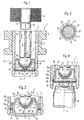
- Fig. 1 is, for example, a valve in the form of a fuel injector for Fuel injection systems of mixed compressed, spark ignited Internal combustion engines are shown schematically in a partial representation. The present However, the invention is not only with fuel injectors, but also with different type of valves for liquid or gaseous media, can be used.
- the fuel injection valve 1 has a plastic injection molding 2 in part surrounded tubular valve seat support 3.
- a longitudinal bore 5 is formed in the longitudinal bore 5 in the exemplary embodiment, tubular valve needle 6 arranged on her downstream end 7 with a spherical in the embodiment Valve closing body 8 e.g. is connected by welding to a weld 9.
- the e.g. Fuel flowing in over the inside of the valve needle 6 can be directed from the side Open openings 10 freely in the longitudinal bore 5 and to the Flow valve closing body 8.
- the fuel injector 1 is actuated in a known manner, for example electromagnetically.
- an indicated electromagnetic circuit with a magnetic coil 11, an armature 12 and one of the Magnetic coil 11 enclosed core 13.
- the armature 12 is with the Valve closing body 8 facing away from the end of the valve needle 6 and connected to the core 13 aligned.
- the valve closing body 8 acts to form a sealing seat with one on one Valve seat body 14 formed valve seat surface 17 together.
- spray plate 15 are spray openings 18 for spraying the valve flowing medium, formed in the embodiment of the fuel.
- the valve seat body 14 and the spray orifice plate 15 are in one one-piece; flat, deformable workpiece 16 integrated.
- two-dimensional workpiece 16 is preferably a sheet metal part through Deep drawing is brought into the cup-shaped form shown in Fig. 1.
- the workpiece 16 is frustoconical, so that the spherical valve closing body 8 on a circumferential line of contact on the Valve seat 17 bears sealingly.
- Valve closing body 8 and the valve seat surface 17 can improve the valve seat surface 17 after the deep drawing of the workpiece 16 by means of a suitable one Post-processing procedures, e.g. by polishing, to be reworked so that the necessary shape accuracy is achieved.
- the section of the workpiece 16 that forms the spray-perforated disk 15 is located downstream of the portion of the workpiece 16 forming the valve seat body 14
- Workpiece 16 is dome-shaped in the flow direction in the area of the spray orifice plate 15 arched so that the preferably several, for example four spray orifices are inclined outwards with respect to the longitudinal valve axis 4. This will make the Spray properties of the fuel injector I further developed according to the invention improved.
- Section of the workpiece 16 is also achieved that the workpiece 16 in the area the spray openings 18 do not abut the spherical valve closing body 8.
- a Guide section 19 is provided upstream of the portion of the workpiece 16 forming the valve seat body 14 .
- the workpiece 16 in the Guide section 19 is polyhedral and has a plurality of guide surfaces 20 that complement each other to form a polyhedron with rounded corners 21.
- the polyhedron can e.g. have five corners 21 and five guide surfaces 20.
- the guide surfaces 20 lie for guiding the valve closing body 8 at contact points 22 on the Valve closing body 8. This results between the contact points 22 Flow passages 23, the unimpeded flow of the flowing through the valve Medium, in the exemplary embodiment of the fuel, up to the valve seat surface 17 enable.
- the flat, deformable workpiece 16 in a turning section 24 in the exemplary embodiment by 180 ° bent over so that an adjoining the turning section 24, radially outer Fastening section 25 in the direction of a circumferential end 26 of the workpiece 16 parallel to the direction of flow of the fuel injector 1 flowing through Medium extends.
- the Fastening section 25 over its entire axial length on the inner wall of the Longitudinal bore 5 of the valve seat support 3 and is at the circumferential end 26 preferably by means of a weld seam 27 with the valve seat support 3 and sealingly connected. Due to the sealing connection between the workpiece 16 and the valve seat support 3 ensures that the fuel injector 1 medium flowing through not bypassing the sealing seat between the Valve seat carrier 3 and the workpiece 16 flows past.
- the end 26 of the workpiece 16 is located downstream of the spray openings 18, see above that the accessibility of the circumferential end 26 for applying the weld seam 27th is ensured. Due to the large area of the attachment portion 26 on the Valve seat support 3 is a heat dissipation of those occurring in the welding process Heating to the valve seat support 3 allows so that the overheating Guide portion 19, the portion forming the valve seat body 14 and the Splash plate 15 forming portion of the workpiece 16 is avoided. Thereby becomes a deformation of these areas during the welding of the workpiece 16th counteracted with the valve seat support 3.
- the spray openings 18 can pass through the workpiece 16 in a manner known per se Stamping, drilling, laser drilling, eroding or another suitable manufacturing process be introduced.
- the spray openings 18 can either not yet deformed blank of the workpiece 16 introduced or at a later date the already deformed workpiece 16 are formed.
- FIG. 3 and 4 show further exemplary embodiments of an only partially in section Fuel injector 1 shown, wherein the fastening portion 25 and the valve seat support 3 compared to that shown in FIG. 1 and already described Embodiment are varied.
- the diameter is that in the Valve seat support 3 provided longitudinal bore 5 compared to that shown in Fig. 1 Embodiment executed enlarged.
- the fastening section 25 of the workpiece 16 is divided into three areas: one at the turning section 24 in Flow direction adjoining first axial section 25a, one to the circumferential End 26 adjoining, lying on the inner wall of the longitudinal bore 5 second axial portion 25c and one of the first and second axial portions 25a and 25c with a radial component connecting radial section 25b.
- the exemplary embodiment is the peripheral end 26 of the workpiece 16 on a sealing, circumferential weld seam 27 welded to the valve seat body 3.
- This embodiment has compared to the embodiment shown in Fig. 1 on the one hand the advantage that the distance between the weld seam 27 and the Guide section 19 and the valve seat body 14 and the spray orifice plate 15 forming sections is extended by the radial section 25b, which is a thermal deformation of the aforementioned areas during the application of the Counteracts weld seam additionally.
- the geometric shape of the workpiece 16 shown in FIG. 3 has the additional significant advantage that a displacement tool 40, which the Stroke adjustment of the fuel injector 1 according to the invention is used on the radial Section 25b of the mounting section 25 can attack freely.
- a displacement tool 40 which the Stroke adjustment of the fuel injector 1 according to the invention is used on the radial Section 25b of the mounting section 25 can attack freely.
- the displacement tool 40 is bell-shaped, so that the Valve seat body 14 and areas of the workpiece 16 forming the spray orifice plate 15 in immerse a bell-shaped recess 41 of the displacement tool 40 if that Shift tool 40 engages the radial portion 25b. This will make one Deformation of the guide portion 19 and the valve seat body 14 and the Aperture plate 15 forming areas during the stroke adjustment axial displacement of the workpiece 16 in the longitudinal bore 5 of the valve seat carrier 3 avoided.
- the second axial section 25c faces the inner diameter of the Longitudinal bore 5 has a slightly larger diameter, so that the second axial Section 25c resiliently presses against the inner wall of the longitudinal bore 5 and that Workpiece 16 locked in the longitudinal bore 5.
- the embodiment shown in FIG. 4 differs from that in FIG. 3 represented in that the first axial portion 25a of the mounting portion 25 of the Workpiece 16 longer and the radial portion 25b and the second axial portion 25c are shortened.
- the longitudinal bore 5 of the valve seat support 3 is on the injection-side end of the valve seat support 3 is formed as a stepped bore and has a Step 5b with an enlarged diameter adjoining the step 5a on the injection side on.
- the second axial section 25c is at the enlarged stepped bore 5b welded, while the first axial section 25a on the step 5a of the longitudinal bore 5th resilient.
- good heat dissipation is associated with the Welding associated heating given to the valve seat support 3, so that thermal deformation of the guide section 19 and the valve seat body 14 and the spray plate 15 forming areas is counteracted.
- the displacement tool 40 can also in this embodiment on the radial Attack section 25b of the fastening section 25 of the workpiece 16, the die Area of the workpiece 16 forming the spray-perforated disk 15 into a recess provided for this purpose 42 of the displacement tool 40 is immersed.
- the workpiece 16 can either be from a hard base material or be partially or completely hardened. It is also conceivable to apply the workpiece 16 by applying a hard material coating e.g. Protect from TiN at least in the areas subject to wear.
- a hard material coating e.g. Protect from TiN at least in the areas subject to wear.
Landscapes
- Engineering & Computer Science (AREA)
- Chemical & Material Sciences (AREA)
- Combustion & Propulsion (AREA)
- Mechanical Engineering (AREA)
- General Engineering & Computer Science (AREA)
- Manufacturing & Machinery (AREA)
- Fuel-Injection Apparatus (AREA)
- Lift Valve (AREA)
Description
Claims (11)
- Ventil, insbesondere Brennstoffeinspritzventil für Brennstoffeinspritzanlagen von Brennkraftmaschinen, mit einem an einem Ventilsitzkörper (14) ausgebildeten Ventilsitz (17), der mit einem betätigbaren Ventilschließkörper (8) zur Ausbildung eines Dichtsitzes zusammenwirkt, und mit einer Spritzlochscheibe (15), die zumindest eine Abspritzöffnung (18) aufweist, wobei der Ventilsitzkörper (14) und die Spritzlochscheibe (15) einstückig aus einem flächigen, verformbaren, ein Metallblechteil darstellenden Werkstück (16) ausgebildet sind, das topfförmig so ausgeformt ist, daß es im Bereich des Ventilsitzes (17) an dem nicht betätigten Ventilschließkörper (8) im geschlossenen Zustand des Ventils (1) dichtend anliegt und in einem Bereich stromabwärts des Ventilsitzes (17) die zumindest eine Abspritzöffnung (18) aufweisende Spritzlochscheibe (15) bildet, dadurch gekennzeichnet, daß der Ventilsitzkörper (14) im Bereich seines Ventilsitzes (17) als Ventilsitzfläche ausgeführt ist und das flächige Werkstück (16) stromaufwärts der Ventilsitzfläche (17) zu einem die Bewegung des Ventilschließkörpers (8) bei dessen Betätigung führenden Führungsabschnitt (19) ausgeformt ist.
- Ventil nach Anspruch 1, dadurch gekennzeichnet, daß das Werkstück (16) durch Tiefziehen verformt ist.
- Ventil nach Anspruch 1 oder 2, dadurch gekennzeichnet, daß das flächige, verformbare Werkstück (16) im Bereich der wenigstens einen Abspritzöffnung (18) der Spritzlochscheibe (15) kalottenförmig gewölbt ist.
- Ventil nach einem der Ansprüche 1 bis 3, dadurch gekennzeichnet, daß der Ventilschließkörper (8) kugelförmig oder teilkugelförmig und die Ventilsitzfläche (17) kegelstumpfförmig ausgebildet sind.
- Ventil nach einem der vorhergehenden Ansprüche, dadurch gekennzeichnet, daß an dem Führungsabschnitt (19) mit dem Ventilschließkörper (8) an Kontaktstellen (22) in Berührung stehende Führungsflächen (20) und zwischen den Kontaktstellen (22) angeordnete Strömungsdurchlässe (23) vorgesehen sind.
- Ventil nach Anspruch 5, dadurch gekennzeichnet, daß der Ventilschließkörper (8) kugelförmig oder teilkugelförmig ausgebildet ist und der Führungsabschnitt (19) polyederförmig, vorzugsweise mit abgerundeten Ecken (21), ausgebildet ist.
- Ventil nach einem der vorhergehenden Ansprüche, dadurch gekennzeichnet, daß das flächige, verformbare Werkstück (16) stromaufwärts des Führungsabschnitts (19) in einem Wendeabschnitt (24) umgebogen ist, so daß ein sich an den Wendeabschnitt (24) anschließender Befestigungsabschnitt (25) in Richtung auf ein umlaufendes Ende (26) des flächigen, verformbaren Werkstücks (16) im wesentlichen parallel zur Strömungsrichtung des durch das Ventil (1) strömenden Mediums erstreckt.
- Ventil nach Anspruch 7, dadurch gekennzeichnet, daß das Ventil (1) einen Ventilsitzträger (3) mit einer Längsbohrung (5) aufweist, in die das flächige, verformbare Werkstück (16) einschiebbar und an dem Befestigungsabschnitt (25) vorzugsweise durch Verschweißen verbindbar ist.
- Ventil nach Anspruch 8, dadurch gekennzeichnet, daß das flächige, verformbare Werkstück (16) mittels eines Verschiebe-Werkzeugs (40) zur Einstellung des Ventilhubs in der Längsbohrung (5) des Ventilsitzträgers (3) verschiebbar ist.
- Ventil nach Anspruch 9, dadurch gekennzeichnet, daß das Verschiebe-Werkzeug (40) an die Form des Werkstücks (16) so angepaßt ist, daß es nur an dem Befestigungsabschnitt (25) und/oder an dem Wendeabschnitt (24) angreift.
- Ventil nach einem der Ansprüche 1 bis 10, dadurch gekennzeichnet, daß das flächige, verformbare Werkstück (16) zumindest im Bereich der Ventilsitzfläche (17) insbesondere durch Beschichten mit einer Hartstoffschicht gehärtet ist.
Applications Claiming Priority (3)
| Application Number | Priority Date | Filing Date | Title |
|---|---|---|---|
| DE19653832 | 1996-12-21 | ||
| DE19653832A DE19653832A1 (de) | 1996-12-21 | 1996-12-21 | Ventil mit kombiniertem Ventilsitzkörper und Spritzlochscheibe |
| PCT/DE1997/002403 WO1998028538A1 (de) | 1996-12-21 | 1997-10-18 | Ventil mit kombiniertem ventilsitzkörper und spritzlochscheibe |
Publications (2)
| Publication Number | Publication Date |
|---|---|
| EP0953108A1 EP0953108A1 (de) | 1999-11-03 |
| EP0953108B1 true EP0953108B1 (de) | 2002-04-03 |
Family
ID=7815889
Family Applications (1)
| Application Number | Title | Priority Date | Filing Date |
|---|---|---|---|
| EP97947687A Expired - Lifetime EP0953108B1 (de) | 1996-12-21 | 1997-10-18 | Ventil mit kombiniertem ventilsitzkörper und spritzlochscheibe |
Country Status (9)
| Country | Link |
|---|---|
| US (1) | US6131826A (de) |
| EP (1) | EP0953108B1 (de) |
| JP (1) | JP3953530B2 (de) |
| KR (1) | KR100553463B1 (de) |
| CN (1) | CN1089859C (de) |
| DE (2) | DE19653832A1 (de) |
| ES (1) | ES2175482T3 (de) |
| RU (1) | RU2187687C2 (de) |
| WO (1) | WO1998028538A1 (de) |
Families Citing this family (35)
| Publication number | Priority date | Publication date | Assignee | Title |
|---|---|---|---|---|
| US6622751B1 (en) * | 1998-02-09 | 2003-09-23 | Continental Teves Ag & Co., Ohg | Pressure valve for a reciprocating pump |
| US6279844B1 (en) * | 1999-03-18 | 2001-08-28 | Siemens Automotive Corporation | Fuel injector having fault tolerant connection |
| DE19927899A1 (de) * | 1999-06-18 | 2000-12-21 | Bosch Gmbh Robert | Brennstoffeinspritzventil |
| JP4158187B2 (ja) * | 2000-05-12 | 2008-10-01 | 株式会社デンソー | 燃料噴射弁 |
| DE10118163B4 (de) * | 2001-04-11 | 2007-04-19 | Robert Bosch Gmbh | Brennstoffeinspritzventil |
| EP1581737B1 (de) * | 2003-01-09 | 2009-05-27 | Continental Automotive Systems US, Inc. | Sprühmustersteuerung mit an einer einen beutelvolumenreduzierer aufweisenden, mit vertiefungen versehenen kraftstoffeinspritzdosierscheibe ausgebildeten nicht abgewinkelten öffnungen |
| DE10319694A1 (de) * | 2003-05-02 | 2004-12-02 | Robert Bosch Gmbh | Brennstoffeinspritzventil |
| US6948665B2 (en) * | 2003-06-30 | 2005-09-27 | Siemens Vdo Automotive Corporation | Fuel injector including an orifice disc, and a method of forming the orifice disc with an asymmetrical punch |
| US7163159B2 (en) * | 2003-07-15 | 2007-01-16 | Siemens Vdo Automotive Corporation | Fuel injector including a compound angle orifice disc |
| US7744020B2 (en) * | 2003-07-21 | 2010-06-29 | Continental Automotive Systems Us, Inc. | Fuel injector including an orifice disc, and a method of forming the orifice disc including punching and shaving |
| DE10360706A1 (de) * | 2003-12-19 | 2005-07-14 | Aweco Appliance Systems Gmbh & Co. Kg | Ventil und Verfahren zum Herstellen eines Ventils |
| US7334746B2 (en) * | 2004-03-08 | 2008-02-26 | Continental Automotive Systems Us, Inc. | Seat-lower guide combination |
| US7159436B2 (en) * | 2004-04-28 | 2007-01-09 | Siemens Vdo Automotive Corporation | Asymmetrical punch |
| US7201329B2 (en) * | 2004-04-30 | 2007-04-10 | Siemens Vdo Automotive Corporation | Fuel injector including a compound angle orifice disc for adjusting spray targeting |
| US7086615B2 (en) | 2004-05-19 | 2006-08-08 | Siemens Vdo Automotive Corporation | Fuel injector including an orifice disc and a method of forming an oblique spiral fuel flow |
| JP4025768B2 (ja) * | 2004-09-27 | 2007-12-26 | 株式会社ケーヒン | 燃料噴射弁 |
| US20060157595A1 (en) * | 2005-01-14 | 2006-07-20 | Peterson William A Jr | Fuel injector for high fuel flow rate applications |
| US20060192036A1 (en) * | 2005-02-25 | 2006-08-31 | Joseph J M | Fuel injector including a multifaceted dimple for an orifice disc with a reduced footprint of the multifaceted dimple |
| EP1856404B8 (de) * | 2005-03-07 | 2009-01-14 | Continental Automotive Systems US, Inc. | Untere führungskombination für sitz |
| DE102005037953B4 (de) * | 2005-08-11 | 2016-12-08 | Robert Bosch Gmbh | Brennstoffeinspritzventil |
| JP4077004B2 (ja) | 2005-10-27 | 2008-04-16 | 三菱電機株式会社 | 燃料噴射弁装置 |
| JP2007146828A (ja) * | 2005-10-28 | 2007-06-14 | Hitachi Ltd | 燃料噴射弁 |
| DE102007028516A1 (de) * | 2007-06-21 | 2008-12-24 | Robert Bosch Gmbh | Magnetventil |
| EP2238337B1 (de) | 2007-12-21 | 2014-12-17 | Robert Bosch GmbH | Brennstoffeinspritzventil |
| CN101532675B (zh) * | 2008-03-13 | 2011-10-19 | 宁波新海电气股份有限公司 | 一种折叠式安全点火枪 |
| DE102010040916A1 (de) * | 2010-09-16 | 2012-03-22 | Robert Bosch Gmbh | Brennstoffeinspritzventil |
| JP5921240B2 (ja) * | 2012-02-10 | 2016-05-24 | 日立オートモティブシステムズ株式会社 | 燃料噴射弁 |
| JP5939669B2 (ja) * | 2012-02-29 | 2016-06-22 | 株式会社ケーヒン | 電磁式燃料噴射弁 |
| JP6059915B2 (ja) * | 2012-08-27 | 2017-01-11 | 日立オートモティブシステムズ株式会社 | 燃料噴射弁 |
| CN103600005B (zh) * | 2013-10-09 | 2016-04-27 | 杭州新坐标科技股份有限公司 | 一种摇臂架的加工成型方法 |
| JP6888146B1 (ja) * | 2020-03-27 | 2021-06-16 | 日立Astemo株式会社 | 直噴式燃料噴射弁 |
| JP2023548331A (ja) | 2020-11-04 | 2023-11-16 | スウェージロック カンパニー | 一体型オリフィス絞り付きバルブ |
| CN116420042B (zh) | 2020-11-06 | 2024-06-21 | 斯瓦戈洛克公司 | 阀腔盖布置 |
| EP4074421B1 (de) * | 2021-04-16 | 2023-04-12 | Danfoss A/S | Zerstäubungsdüsenanordnung |
| WO2022254981A1 (ja) * | 2021-06-03 | 2022-12-08 | 日立Astemo株式会社 | 燃料噴射弁 |
Family Cites Families (15)
| Publication number | Priority date | Publication date | Assignee | Title |
|---|---|---|---|---|
| US3224684A (en) * | 1963-04-16 | 1965-12-21 | Hartford Machine Screw Co | Fuel injection nozzle |
| DE2460111A1 (de) * | 1974-04-13 | 1976-07-15 | Daimler Benz Ag | Einspritzventil |
| US4482129A (en) * | 1982-06-10 | 1984-11-13 | The United States Of America As Represented By The United States Department Of Energy | All metal valve structure for gas systems |
| DE3884336T2 (de) * | 1987-10-19 | 1994-01-20 | Ford Werke Ag | Silikon-Ventileinrichtung zur Kontrolle des Durchflusses. |
| US4828184A (en) * | 1988-08-12 | 1989-05-09 | Ford Motor Company | Silicon micromachined compound nozzle |
| DE3841142C2 (de) * | 1988-12-07 | 1994-09-29 | Bosch Gmbh Robert | Einspritzventil |
| US4897907A (en) * | 1989-03-31 | 1990-02-06 | Stanadyne Automotive Corp. | Process for manufacturing nozzle tip |
| JP2592542B2 (ja) * | 1990-11-24 | 1997-03-19 | 株式会社日立製作所 | 電磁バルブのノズルの製造方法 |
| DE4104019C1 (de) * | 1991-02-09 | 1992-04-23 | Robert Bosch Gmbh, 7000 Stuttgart, De | |
| DE4131535A1 (de) * | 1991-09-21 | 1993-03-25 | Bosch Gmbh Robert | Elektromagnetisch betaetigbares einspritzventil |
| DE4221185A1 (de) * | 1992-06-27 | 1994-01-05 | Bosch Gmbh Robert | Spritzlochscheibe für ein Ventil und Verfahren zur Herstellung |
| US5286002A (en) * | 1993-01-12 | 1994-02-15 | Siemens Automotive L.P. | Fuel injector having a composite silicon valve |
| EP0611886B1 (de) * | 1993-02-17 | 1998-12-23 | Denso Corporation | Flüssigkeiteinspritzventil |
| JPH0763140A (ja) * | 1993-08-27 | 1995-03-07 | Toyota Motor Corp | 燃料噴射弁の噴射孔の形成方法 |
| DE4446241A1 (de) * | 1994-12-23 | 1996-06-27 | Bosch Gmbh Robert | Brennstoffeinspritzventil |
-
1996
- 1996-12-21 DE DE19653832A patent/DE19653832A1/de not_active Withdrawn
-
1997
- 1997-10-18 KR KR1019997003776A patent/KR100553463B1/ko not_active Expired - Fee Related
- 1997-10-18 ES ES97947687T patent/ES2175482T3/es not_active Expired - Lifetime
- 1997-10-18 JP JP52819798A patent/JP3953530B2/ja not_active Expired - Fee Related
- 1997-10-18 DE DE59706912T patent/DE59706912D1/de not_active Expired - Lifetime
- 1997-10-18 WO PCT/DE1997/002403 patent/WO1998028538A1/de not_active Ceased
- 1997-10-18 US US09/331,351 patent/US6131826A/en not_active Expired - Fee Related
- 1997-10-18 EP EP97947687A patent/EP0953108B1/de not_active Expired - Lifetime
- 1997-10-18 RU RU99115477/06A patent/RU2187687C2/ru not_active IP Right Cessation
- 1997-10-18 CN CN97180805A patent/CN1089859C/zh not_active Expired - Fee Related
Also Published As
| Publication number | Publication date |
|---|---|
| JP2001507097A (ja) | 2001-05-29 |
| KR100553463B1 (ko) | 2006-02-22 |
| CN1240501A (zh) | 2000-01-05 |
| ES2175482T3 (es) | 2002-11-16 |
| JP3953530B2 (ja) | 2007-08-08 |
| US6131826A (en) | 2000-10-17 |
| KR20000052911A (ko) | 2000-08-25 |
| DE19653832A1 (de) | 1998-06-25 |
| CN1089859C (zh) | 2002-08-28 |
| WO1998028538A1 (de) | 1998-07-02 |
| RU2187687C2 (ru) | 2002-08-20 |
| EP0953108A1 (de) | 1999-11-03 |
| DE59706912D1 (de) | 2002-05-08 |
Similar Documents
| Publication | Publication Date | Title |
|---|---|---|
| DE19653832A1 (de) | Ventil mit kombiniertem Ventilsitzkörper und Spritzlochscheibe | |
| EP0497931B1 (de) | Einspritzventil und verfahren zur herstellung eines einspritzventils | |
| EP0720691B1 (de) | Ventilnadel für ein elektromagnetisch betätigbares ventil und verfahren zur herstellung | |
| DE19712589C1 (de) | Brennstoffeinspritzventil und Verfahren zur Herstellung einer Ventilnadel eines Brennstoffeinspritzventils | |
| EP0944769B1 (de) | Brennstoffeinspritzventil | |
| EP0553310B1 (de) | Brennstoffeinspritzventil | |
| DE4310719C2 (de) | Verfahren zur Herstellung eines Magnetkreises für ein Ventil | |
| EP0865574A1 (de) | Brennstoffeinspritzventil und verfahren zur herstellung | |
| EP1114249B1 (de) | Brennstoffeinspritzventil | |
| DE19631066A1 (de) | Brennstoffeinspritzventil | |
| EP1062421B1 (de) | Brennstoffeinspritzventil | |
| DE4018256A1 (de) | Elektromagnetisch betaetigbares brennstoffeinspritzventil | |
| EP0718491A1 (de) | Ventil und Verfahren zur Herstellung eines Ventiles | |
| WO1997013977A1 (de) | Elektromagnetisch betätigbares ventil, insbesondere brennstoffeinspritzventil | |
| EP0504147B1 (de) | Elektromagnetisch betätigbares kraftstoffeinspritzventil | |
| DE102005040361A1 (de) | Metallische Pressverbindung und Brennstoffeinspritzventil mit einer metallischen Pressverbindung | |
| DE4229730A1 (de) | Elektromagnetisch betätigbares Brennstoffeinspritzventil | |
| EP1200729B1 (de) | Verfahren zur einstellung des ventilhubs eines einspritzventils | |
| EP0925441B1 (de) | Elektromagnetisch betätigbares ventil | |
| DE4108665C2 (de) | Einstellbuchse für ein elektromagnetisch betätigbares Ventil | |
| DE102005040363B4 (de) | Brennstoffeinspritzventil | |
| DE10059263B4 (de) | Verfahren zur Herstellung bzw. zur Montage eines Brennstoffeinspritzventils | |
| DE19627090A1 (de) | Brennstoffeinspritzventil | |
| EP1105641A1 (de) | Brennstoffeinspritzventil | |
| DE102007049966A1 (de) | Brennstoffeinspritzventil und Verfahren zur Montage eines Brennstoffeinspritzventils |
Legal Events
| Date | Code | Title | Description |
|---|---|---|---|
| PUAI | Public reference made under article 153(3) epc to a published international application that has entered the european phase |
Free format text: ORIGINAL CODE: 0009012 |
|
| 17P | Request for examination filed |
Effective date: 19990721 |
|
| AK | Designated contracting states |
Kind code of ref document: A1 Designated state(s): DE ES FR GB IT |
|
| GRAG | Despatch of communication of intention to grant |
Free format text: ORIGINAL CODE: EPIDOS AGRA |
|
| 17Q | First examination report despatched |
Effective date: 20010509 |
|
| GRAG | Despatch of communication of intention to grant |
Free format text: ORIGINAL CODE: EPIDOS AGRA |
|
| GRAH | Despatch of communication of intention to grant a patent |
Free format text: ORIGINAL CODE: EPIDOS IGRA |
|
| GRAH | Despatch of communication of intention to grant a patent |
Free format text: ORIGINAL CODE: EPIDOS IGRA |
|
| REG | Reference to a national code |
Ref country code: GB Ref legal event code: IF02 |
|
| GRAA | (expected) grant |
Free format text: ORIGINAL CODE: 0009210 |
|
| AK | Designated contracting states |
Kind code of ref document: B1 Designated state(s): DE ES FR GB IT |
|
| REF | Corresponds to: |
Ref document number: 59706912 Country of ref document: DE Date of ref document: 20020508 |
|
| GBT | Gb: translation of ep patent filed (gb section 77(6)(a)/1977) |
Effective date: 20020701 |
|
| ET | Fr: translation filed | ||
| REG | Reference to a national code |
Ref country code: ES Ref legal event code: FG2A Ref document number: 2175482 Country of ref document: ES Kind code of ref document: T3 |
|
| PLBE | No opposition filed within time limit |
Free format text: ORIGINAL CODE: 0009261 |
|
| STAA | Information on the status of an ep patent application or granted ep patent |
Free format text: STATUS: NO OPPOSITION FILED WITHIN TIME LIMIT |
|
| 26N | No opposition filed |
Effective date: 20030106 |
|
| PGFP | Annual fee paid to national office [announced via postgrant information from national office to epo] |
Ref country code: GB Payment date: 20030930 Year of fee payment: 7 |
|
| PGFP | Annual fee paid to national office [announced via postgrant information from national office to epo] |
Ref country code: ES Payment date: 20031023 Year of fee payment: 7 |
|
| PG25 | Lapsed in a contracting state [announced via postgrant information from national office to epo] |
Ref country code: GB Free format text: LAPSE BECAUSE OF NON-PAYMENT OF DUE FEES Effective date: 20041018 |
|
| PG25 | Lapsed in a contracting state [announced via postgrant information from national office to epo] |
Ref country code: ES Free format text: LAPSE BECAUSE OF NON-PAYMENT OF DUE FEES Effective date: 20041019 |
|
| GBPC | Gb: european patent ceased through non-payment of renewal fee |
Effective date: 20041018 |
|
| REG | Reference to a national code |
Ref country code: ES Ref legal event code: FD2A Effective date: 20041019 |
|
| PGFP | Annual fee paid to national office [announced via postgrant information from national office to epo] |
Ref country code: FR Payment date: 20101109 Year of fee payment: 14 |
|
| PGFP | Annual fee paid to national office [announced via postgrant information from national office to epo] |
Ref country code: IT Payment date: 20101023 Year of fee payment: 14 |
|
| REG | Reference to a national code |
Ref country code: FR Ref legal event code: ST Effective date: 20120629 |
|
| PG25 | Lapsed in a contracting state [announced via postgrant information from national office to epo] |
Ref country code: IT Free format text: LAPSE BECAUSE OF NON-PAYMENT OF DUE FEES Effective date: 20111018 Ref country code: FR Free format text: LAPSE BECAUSE OF NON-PAYMENT OF DUE FEES Effective date: 20111102 |
|
| PGFP | Annual fee paid to national office [announced via postgrant information from national office to epo] |
Ref country code: DE Payment date: 20161213 Year of fee payment: 20 |
|
| REG | Reference to a national code |
Ref country code: DE Ref legal event code: R071 Ref document number: 59706912 Country of ref document: DE |