EP0952474B1 - Projection lens and focus adjusting method for projection lens - Google Patents
Projection lens and focus adjusting method for projection lens Download PDFInfo
- Publication number
- EP0952474B1 EP0952474B1 EP99303114A EP99303114A EP0952474B1 EP 0952474 B1 EP0952474 B1 EP 0952474B1 EP 99303114 A EP99303114 A EP 99303114A EP 99303114 A EP99303114 A EP 99303114A EP 0952474 B1 EP0952474 B1 EP 0952474B1
- Authority
- EP
- European Patent Office
- Prior art keywords
- lens
- lens group
- projection
- optical path
- denotes
- Prior art date
- Legal status (The legal status is an assumption and is not a legal conclusion. Google has not performed a legal analysis and makes no representation as to the accuracy of the status listed.)
- Expired - Lifetime
Links
Images


Classifications
-
- G—PHYSICS
- G02—OPTICS
- G02B—OPTICAL ELEMENTS, SYSTEMS OR APPARATUS
- G02B13/00—Optical objectives specially designed for the purposes specified below
- G02B13/06—Panoramic objectives; So-called "sky lenses" including panoramic objectives having reflecting surfaces
-
- H—ELECTRICITY
- H04—ELECTRIC COMMUNICATION TECHNIQUE
- H04N—PICTORIAL COMMUNICATION, e.g. TELEVISION
- H04N5/00—Details of television systems
- H04N5/74—Projection arrangements for image reproduction, e.g. using eidophor
Definitions
- the present invention relates to a projection lens, and is suitably applied to a projection lens equipped to a projection device such as a projection display device.
- a so-called back projection type projection display device which performs a display operation by projecting image light to a transmission type screen from the back side thereof.
- flux of light obtained by collimating light of a white light source by a reflector or the like is decomposed into three-color light flux of red, green and blue by a color-separating mirror.
- each two-dimensional image display element for example, LCD: Liquid Crystal Display
- LCD Liquid Crystal Display
- RGB Red, green, blue
- Image light obtained on the respective two-dimensional image display elements corresponding to red, green and blue is color-composed into white color in a color composing optical system, and projected onto a transmission type screen through a projection lens while being enlarged.
- the projection display device has a structure of converting an optical path by 90° in a lens system constituting a projection lens.
- the arrangement direction of the housing of a projection device in a projection display device and the mount direction of various optical elements from color separation until color composition in the projection device can be changed, and further the various optical elements can be miniaturized, whereby miniaturization of the projection display device is allowed.
- a so-called back focus which corresponds to the distance from the two-dimensional image display element to the rear end of the projection lens must be set to be long on the basis of a restriction on the necessity of arranging an optical element such as a dichroic prism, a dichroic mirror or the like as the color composition optical system.
- the projection distance for example, the central light beam length extending from the emission end of the projection lens through the mirror to the transmission type screen
- the projection lens is made to have a wider angle and the divergence angle of emitted light is increased, thereby obtaining a large-size frame.
- the projection lens has telecentricity so that the principal ray out of the axis of the projection lens is vertical to the two-dimensional image display element.
- the lens is symmetrical with respect to the light beam passing the center of the two-dimensional image display element, whereas the two-dimensional image display element itself has a higher contrast in only one direction, so that the light flux itself irradiated to the two-dimensional image display element is required to have an angle.
- a display device such as LCD or the like is ordinarily used as the two-dimensional image display element, and unlike a case using CRT, it is difficult to correct distortion of the projection lens because LCD is driven by using a matrix electrode. That is, in the case of CRT; the distortion of the projection can be relatively easily corrected by using a raster-shaped correction function such as a pin-cushion distortion correction or the like. On the other hand, in the case of the display device for performing dot matrix display like LCD, such a raster distortion correction is not ordinarily performed.
- the present invention provides a projection lens according to claim 1, and a focus adjusting method for such a projection lens, according to claim 10.
- the present invention provides a projection lens for performing an optical path conversion in a system of the projection lens, which has a wide view angle, a long back focus and a large out-of-axis light amount at a short projection distance and telecentricity, and also has small distortion aberration and small other aberrations. Further, the present invention enables a focus adjustment which is suitable for a case where the optical path conversion is performed in the system of the projection lens.
- the invention forms a projection lens in an arrangement of a first lens group having a refractive power and an aspherical surface, a second lens group which has a positive refractive power so as to be spaced at the largest central air spacing in the overall system and is formed so as to have at least one positive lens, and a third lens group having a positive refractive power and an aspherical surface, which are arranged from a long conjugate side to a short conjugate side in this order, optical path conversion means which is inserted between the first lens group and the second lens group and converts an optical path of light flux which is to extend from said first lens group to said second lens group.
- an air interval in which the optical path conversion means can be disposed is kept between the first lens group and the second lens group, and an inverse telescope type lens construction can be obtained as a wide-angle lens having a long back focus. Further, the construction is made so that the out-of-axis principal light beam is emitted to the high position of the third lens group, whereby the telecentricity of the out-of-axis principal light beam incident to the face of a two-dimensional image display element such as a liquid crystal panel or the like can be obtained.
- the projection lens having optical path conversion means a wide-angle lens having a long back focus which is needed, for example, when a projection lens is used for a projection display device, can be formed, and an inverted telescope type lens construction can be obtained. That is, a large-size screen can be obtained with a short projection.
- the third lens group having at least a laminated lens and a positive lens and having an aspherical surface lens at the shortest conjugate side represents the composite focus distance of the third lens group by F3; the composite focus distance of the laminated lens of the third lens group by F31; the composite focus distance of the positive lens of the third lens group by FP32; the composite focus distance of the positive lens and the aspherical surface lens of the third lens group by F32; and the composite focus distance of the aspherical surface lens of the third lens group by FP33, so that the following equation is satisfied: 1.00 ⁇ -F31/F3 ⁇ 2.50 0.9 ⁇ FP32/F3 ⁇ 1.40 2.00 ⁇ FP33 ⁇ F32
- the balance of the refractive power of the positive lens constituting the laminated lens in the third lens group, the balance of the refractive power of the positive lens in the third lens group and the balance of the refractive power of the aspherical lens in the third lens group are defined, and an excellent correction state of various aberrations can be achieved.
- the laminated lens of the third lens group is composed of a negative lens and a positive lens in the direction from a long conjugate side to a short conjugate side, and representing the refractive index of a negative lens constituting said laminated lens of said third lens group by N3N; the refractive index of a positive lens constituting said laminated lens of said third lens group by N3P; Abbe number of a positive lens constituting said laminated lens of said third lens group by V3P; and Abbe number of a negative lens constituting said laminated lens of said third lens group by V3N, the following equation is satisfied: N3N - N3P > 0.15 V3P - V3N > 27 Whereby a suitable value is obtained as the refractive index of the laminated lens in the third lens group to enable a suitable color correction.
- the optical path conversion means is provided so that an optical path is bent along a long side of a two-dimensional image display element to be disposed at the focus position of the entire system of the projection lens, or it is provided so that an optical path is bent along a short side of a two-dimensional image display element to be displaced at the focus position of the entire system of the projection lens, whereby the setting of the arrangement direction in the projection display device of the projection device having the projection lens can be changed.
- the optical path conversion means is composed of a mirror or prism for totally reflecting only P-wave or S-wave. Therefore, there can be supported at a low cost a case where the projection device having the projection lens concerned is designed to handle flux of light of a polarization plane of any one of P-wave and S-wave.
- a projection lens for performing therein the optical conversion which can project with high contrast especially in a projection device using a liquid crystal panel, which has a wide angle, a short projection distance, a long back focus and a telecentricity, and further which is reduced in various aberrations such as distortion aberration, etc.
- the projection display device is constructed by applying the projection lens of the present invention to a projection device using a liquid crystal panel as a two-dimensional image display element, a thin type one whose depth, etc. are reduced correspondingly can be obtained, and also an excellent image quality is expected.
- a focus adjusting method for a projection lens in which in an arrangement of a first lens group having a refractive power and an aspherical surface, a second lens group which has a positive refractive power so as to be spaced at the largest central air spacing in the overall system and is formed so as to have at least one positive lens, and a third lens group having a positive refractive power and an aspherical surface, which are arranged from a long conjugate side to a short conjugate side in this order, optical path conversion means which is inserted between the first lens group and the second lens group and converts an optical path of light flux which is to extend from the first lens group to the second lens group is provided, and representing a back focus at a projection distance of infinite point by BF; the composite focus distance of the entire system by F; the central air spacing between the first lens group and the second lens group by GD1; the composite focus distance of the first lens group by F1; the composite focus distance of the second lens group and the third lens group by F23; and
- the focus adjustment of the light flux focused on the screen which is arranged, for example, at the long conjugate side is performed by the lens group through which the light flux after the optical path is converted by the optical path conversion means passes.
- the focus adjustment work can be easily performed without inducing the phenomenon that the image center on the screen deviates.
- a projection lens according to an embodiment of the present invention will be described hereunder. The description is made on the assumption that the projection lens of this embodiment is to provide with a projection device of a back projection type projection display device using LCD as a two-dimensional image display element.
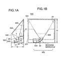
- Figs. 1A and Fig. 1B are side view and front view of an example of the overall construction of the projection display device.
- a projection display device 500 shown in these figures is provided with a bending mirror 504 on the back surface of a cabinet 501 thereof, and a transmission type screen 21 is provided to the front surface of the cabinet 501.
- the bending mirror 504 is secured to have an angle at which image light projected from a projection device which will be next described can be reflected and projected to a screen 504.
- the projection device 502 is disposed at the lower side in a cabinet 501 as shown in the figure.
- a light source described later, a dichroic mirror, a liquid crystal panel block and optical parts such as a dichroic prism (light composition element), etc. are disposed in the cabinet 503 of the projection device 502, and flux of light is obtained as image light by the operation of the above elements.
- the light flux as the image light thus obtained is projected by a projection lens 20, and emitted as projection light 600.
- a bending mirror M for converting the optical path is disposed in the optical path of the lens system constituting the projection lens 20. Accordingly, in this embodiment, the light flux as the image light is bent in the projection lens 20.
- the projection light 600 is emitted upwardly from the projection lens 20 so as to be irradiated onto the bending mirror 504.
- the optical path of the projection light 600 emitted from the projection lens 20 is bent by the bending mirror 504, and irradiated to the screen 21.
- On the screen 21 is disposed an enlarged image obtained by the projection light projected from the projection lens 20.
- a viewer views the screen 21 from the opposite direction to the arrangement position of the projection lens 20 to enjoy the display image.
- the method of converting the optical path in the projection lens 20 as shown in Fig. 1 is mainly used to aim at the miniaturization of cabinet 501 of the projection display device 500.
- the cabinet 503 itself of the projection device 502 is substantially flatly placed (actually, as is apparent from the illustration of Fig. 1A, it is obliquely placed so that the projection light 600 is suitably irradiated to the bending mirror 504), and the cabinet 503 can be disposed so that the front surface (the side surface at the side where the projection device 502 is secured)/back surface of the cabinet 503 confronts the side surface of the cabinet 501 of the projection display device 500.
- the depth D of the cabinet 501 of the projection display device 500 can be reduced. Further, since the space of a portion at the lower side of the screen 21 in the cabinet 501 of the projection display device 500 can be reduced, the height H of the cabinet 501 can be reduced.
- the projection display device for which the present invention is used is not limited to the construction shown in Fig. 1, and the mount manner of the projection device in the cabinet of the projection display device may be suitably changed in accordance with the optical path conversion direction in the projection lens of the projection device or the like.
- Fig. 2 conceptually shows the internal construction of a first example as the projection device 502 in which the projection lens of this embodiment can be mounted.
- the portions other than the screen 21 constitutes the projection device 502.
- a bending mirror 504 is provided between the projection lens 20 and the screen 21 as the structure of the projection display device, and the optical path is converted by a bending mirror M in the projection lens 20.
- both of the bending mirror 504 in Fig. 2 and the projection lens 20 having the structure corresponding to the optical path conversion are omitted from Fig.2.
- a lamp 1 as a light source comprising a metal halide lamp or the like is disposed at a focus position of a reflector 2 (parabolic plane mirror). Light irradiated from the lamp 1 is reflected from the reflector 2 and collimated to be substantially parallel to the optical axis, and then emitted from the opening potion of the reflector 2.
- Undesired light beams in the infrared area and the ultraviolet area in the light emitted from the opening portion of the reflector 2 are intercepted by an IR-UV cut filter 3, and only light beams which are effective to display are guided to various optical elements disposed at subsequent stages.
- a multi-lens array 5 is disposed subsequently to a multi-lens array 4.
- the multi-lens array 4 is designed in such a flat shape that a plurality of convex lenses whose outlook is similar to a shape having the same aspect ratio as the effective opening of each liquid crystal panel serving as optical modulation means described later are arranged in a zigzag form while they are deviated in phase by 1/2.
- the multi-lens array 5 is designed in a flat convex form so that a plurality of convex lenses 5a are formed at the side thereof which confronts the convex lenses of the multi-lens array 4.
- Dichroic mirrors 6, 10 for separating the light flux from the lamp 1 into red, green and blue colors are disposed between the multi-lens array 5 and the effective opening of the liquid crystal panel block liquid crystal.
- the light flux R of red color is first reflected by the dichroic mirror 6, and the light flux G of green and the light flux B of blue are transmitted therethrough.
- the propagation direction of the light flux R of red which is reflected by the dichroic mirror 6 is bent by 90° by the mirror 7, and then guided to a condenser lens 8 before the liquid crystal panel block 9 for red.
- the green and blue light flux G, B transmitted through the dichroic mirror 6 are separated by the dichroic mirror 10. That is, the green light flux G is reflected to bend the propagation direction thereof by 90° and then guided to a condenser lens 11 before the green liquid crystal panel 12.
- the blue light flux B is transmitted through the dichroic mirror 10, propagates straightly, and then is guided through a relay lens 13, a mirror 14, an inverting relay lens 15 and a mirror 16 to a condenser lens 17 before the blue liquid crystal panel 18.
- each of the red, green and blue light flux R,G,B is transmitted through each condenser lens 8, 11, 17 and incident to the liquid crystal panel block 9, 12, 18 for each color.
- Each color liquid crystal panel block 9, 12, 18 is provided with a liquid crystal panel, and also with an incident side polarizer for aligning the polarization direction of the light beams incident to the front stage of the liquid crystal panel to a fixed direction. Further, a so-called analyzer for passing therethrough only light having a predetermined polarization plane in emitted light is disposed at the subsequent stage of the liquid crystal panel, whereby the light intensity is modulated by a voltage of a circuit for driving the liquid crystal.
- each liquid crystal panel block 9, 12, 18 is disposed so that the polarization plane parallel to the sheet of Fig. 1 is transmitted therethrough.
- a TNT type is used as each liquid crystal panel constituting the liquid crystal panel block 9, 12, 18, and the operation thereof is set to a so-called normally white type.
- the analyzer is disposed so that polarized light vertical to the sheet of Fig. 1 is transmitted.
- Each color light flux which is optically modulated by the liquid crystal panel block 9, 12, 18 is incident to each face shown in the figure in the light composition element (cross dichroic prism) 19.
- This light composition element is formed by combining a prism having a predetermined shape with reflection films 19a, 19b.
- the red light flux R in the light composition element is reflected from the reflection film 19a, the blue light flux B is reflected from the reflection film 19b, and they are incident to the projection lens 20.
- the green light flux G straightly propagates in the light composition element 19 while transmitted therethrough, and is incident to the projection lens 20, whereby the light flux R, the light flux G and the light flux B are incident to the projection lens 20 while being composed into one light flux.
- the light flux incident from the light composition element 19 is converted to projection light, and projected to the transmission type screen 21, for example.
- the optical path is converted by 90° in the projection lens 20, it is reflected by the bending mirror 504 (fig.1) disposed in the projection display device and then the light flux is irradiated to the screen 21.
- Fig. 3 conceptually shows the internal construction as a second example of the projection device 502 in which the projection lens of this embodiment can be mounted.
- the same parts as Fig. 2 are represented by the same reference numerals, and the description thereof is omitted.
- the light flux B is reflected by a dichroic mirror 6A at the subsequent stage of the multi-lens array 5, and the light flux R, the light flux G are allowed to pass.
- the light flux B reflected from the dichroic mirror 6A is reflected from a mirror 7A, passed through a condenser lens 8A, optically modulated through the blue liquid crystal panel block 9A, and then it is incident to the light composition element 19A from the direction shown in Fig. 3.
- the light flux R, the light flux G passing through the dichroic mirror 6A is incident to a dichroic mirror 10A at the subsequent stage thereof.
- the light flux R is reflected from the dichroic mirror 10A whereas the light flux G is passed therethrough.
- the light flux R reflected from the dichroic mirror 10A is passed through the condenser lens 11A, optically modulated through a liquid crystal panel block 12A for red, and then incident to the light composition element 19A-a from the direction shown in the figure.
- the light flux G passing through the dichroic mirror 10A arrives at the condenser lens 17A through the relay lens 13A, the mirror 14A, the inverting relay lens 15A and the mirror 16A. Thereafter, it is passed through the condenser lens 17A, optically modulated through the liquid crystal panel block 18A for green and then incident to the light composition element 19A-b from the direction shown in the figure.
- the light composition element 19A is also formed by combining a prism having a predetermined shape with reflection films 19A-a, 19A-b.
- the light flux B is reflected from the reflection film 19A-b and incident to the projection lens 20.
- the light flux G is reflected from the reflection film 19A-a, and incident to the projection lens 20.
- the light flux R is passed through the light composition element 19A while straightly propagates therethrough, and then incident to the projection lens 20.
- the respective light flux R, G, B is composed into one light flux and incident to the projection lens 20.
- Fig. 4 conceptually shows the internal construction of a third example of the projection display device in which the projection lens of this embodiment can be mounted.
- the same parts as Figs. 2 and 3 are represented by the same reference numerals, and the description thereof is omitted.
- the light flux g is reflected by the dichroic mirror 6B, and the light flux R, the light flux B are allowed to pass therethrough.
- the light flux G reflected from the dichroic mirror 6B is incident to the light composition element 19B from the direction shown in Fig. 4 through a mirror 7B, a condenser lens 8B and a liquid crystal panel block 9B for green.
- the light flux R, the light flux B passing through the dichroic mirror 6B are incident to the dichroic mirror 10B, and the light flux R is reflected therefrom while the light flux B is passed therethrough,
- the light flux R reflected by the dichroic mirror 10B is incident through a condenser lens 11B and a liquid crystal panel block 12B for red color to the light composition element 19B from the direction indicated in the figure.
- the light flux B passing through the dichroic mirror 10B is incident to the light composition element 19B from the direction indicated in the figure through a relay lens 13B, a mirror 14B, an inverting relay lens 15B, a mirror 16B, a condenser lens 17B and a liquid crystal panel block 18B for blue in turn.
- the light composition element 19B is also formed by combining a prism having a predetermined shape with reflection films 19B-a, 19B-b.
- the light flux g is reflected by the reflection film 19B-a
- the light flux B is reflected by the reflection film 19B-a
- the light flux R is passed through the light composition element 19B while straightly propagating therethrough, whereby they are incident as one light flux to the projection lens 20.
- the description on the projection device of this embodiment has been made by providing three examples. However, they are only examples, and thus various constructions may be considered as the internal construction of the projection display device in which the projection lens of this embodiment can be mounted.
- first to third embodiments will be hereunder described as the projection of the embodiment of the present invention.
- the projection lenses of these first to third embodiments are used as the projection lens 20 in the projection display device shown in Figs. 1 to 3.
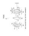
- Fig. 5 is a lens cross-sectional view which conceptually shows the lens arrangement structure of the projection lenses 20 as the first, second and third embodiments.
- the left upper side of the Fig. 5 (the upper side of a mechanical lens 101) is set as a screen 21 side (long conjugate side), and the right side is set as a liquid crystal panel block and light composition element side (short conjugate side).
- a first lens group 100, a second lens group 200 and a third lens group 300 are successively arranged from a long conjugate side to a short conjugate side. Further, a bending mirror M is provided between the first lens group 100 and the second lens group 200.
- the first lens group 100 comprises a meniscus lens 101 having a projecting shape at the long conjugate side and a concave lens 102 having a recess shape at the short conjugate side, which are arranged from the long conjugate side to the short conjugate side, thereby providing negative refractive power.
- both the surfaces of the meniscus lens 101 have an aspherical surface which is conformed with an aspherical coefficient in a numerical value embodiment described later.
- the second lens group 200 is composed of one positive lens 201 to be provided with positive refractive power.
- the air interval between the second lens group 200 and the first lens group can be provided with such a distance that the bending mirror M can be arranged, and also desired performance as the projection lens can be achieved.
- the third lens group 300 is composed of a laminated lens 301 and a positive lens 304 from the long conjugate side, and a convex-shaped meniscus lens 305 at the short conjugate side, which are arranged as shown in the figure, whereby it has positive refractive power.
- the laminated lens 301 is formed by arranging a double-concave lens (negative lens) 302 and a position lens 303 from the long conjugate side to the short conjugate side and laminating the convex surfaces of the double-concave lens 302 and the positive lens 303 to each other.
- meniscus lens 305 has an aspherical surface indicated by the numerical value embodiment described later on both the surfaces thereof.
- the light composition element and the liquid crystal panel block are shown at the short conjugate side of the third lens group, however, it is conceptually illustrated that the light composition element and the liquid crystal panel block are merely located at the light incident side as a positional relationship with the projection lens.
- the light composition element 19 and the liquid crystal panel blocks (9, 12, 18) are illustrated in this figure.
- the light composition element 19A and the liquid crystal panel blocks (9A, 12A, 19A) or the light composition element 19B are illustrated.
- the bending mirror M is provided to reflect the light flux from the second lens group 200 therefrom and convert the optical path, and then make the light flux incident to the first lens group 100, thereby promoting the miniaturization design of the cabinet of the projection display device as described with reference to Fig. 1.
- the bending mirror M is arranged in the projection lens 20 so as to convert the optical path of the light flux from the second lens group 200 by 90°, and in this case the following two methods may be considered by converting the optical path of the light flux from the second lens group 200 by 90° .
- a display area of the liquid crystal panel block is designed in a rectangular form to have a pair of long sides and a pair of short sides in association with an aspect ratio of images.
- the optical path conversion when the optical path conversion is performed on the basis of the liquid crystal panel block by the bending mirror M, there may be considered a method of converting the optical path by 90° along the long-side direction of the liquid crystal panel block and a method of converting the optical path by 90° along the short-side direction.
- Fig. 5 is a designed so that the optical path is converted by 90° along the long-side direction of the liquid crystal panel block, the side edge (cross-sectional portion) of the liquid crystal panel block shown in the figure becomes the long side.
- Fig. 5 is designed so that the optical path is converted by 90° along the short-side direction of the liquid crystal panel block, the side edge (cross-sectional portion) of the liquid crystal panel block shown in the figure becomes the short side.
- the cabinet of the projection display device can be miniaturized, and if the construction of the projection display device shown in Fig. 1 is used, for example, it is better to perform the optical path conversion along the long-side direction of the liquid crystal panel block. The reason is as follows.
- the light flux of modulated image light which is incident from the liquid crystal panel block to the projection lens 20 is first reflected by the bending mirror M in the projection lens to convert the optical path, and it is further reflected by the bending mirror 504 provided to the cabinet 501 of the projection display device to convert the optical path and then incident to the screen 21.
- the modulated image light from the liquid crystal panel block is projected to the screen through the two mirrors having the positional relationship shown in Fig. 1. At this time, the image is rotated by 90° through a process in which it passes from the liquid crystal panel block to the screen 21.
- the liquid crystal panel block is arranged so that the long-side direction thereof (the horizontal direction for the image) corresponds to the longitudinal direction, whereby the image is finally displayed on the screen 21 in such a proper state that the long-side direction of the image corresponds to the horizontal direction.
- various optical elements constituting the other projection device 502 are arranged so that the long-side direction corresponds to the longitudinal direction.
- the optical path of the light flux is converted by 90° along the long-side direction of the cabinet 503 which is arranged so that the long-side direction of the liquid crystal panel block and the other optical elements corresponds to the longitudinal direction.
- the optical path is converted as shown in Fig. 1. That is, the optical path is converted to direct upwardly with respect to the cabinet 503 of the projection device.
- the projection device 502 when the projection device 502 is arranged so that the long-side directions of the parts constituting the liquid crystal panel block, the other optical elements, etc. correspond to the longitudinal direction, the short-side corresponds to the lateral direction. Therefore, as compared with the case where the it is disposed so that the short-side directions of the various parts correspond to the longitudinal direction, the width W of the cabinet 503 of the projection device 502 can be more easily reduced. Further, in accordance with the arrangement of the internal various constituent part, the various constituent parts themselves can be miniaturized.
- the miniaturization of the cabinet 503 of the projection device 502 can be performed more effectively, thereby promoting the miniaturization (particularly, the reduction in depth) of the projection display device 500.
- As means of converting the optical path in the projection lens 20 may be considered not only a member having a mirror structure such as the above bending mirror M or the like, but also a member using a prism or the like.
- liquid crystal panel block is used as the projection device like this embodiment, only the polarization direction of any one of S-wave and P-wave is used as light being actually used.
- the coating may be performed so that high reflectance is provided only in the polarization direction of any one of S-wave and P-wave in connection with the polarization plane of the light flux which is finally emitted from the optical composition element (19, 19A, 19B).
- the optical path conversion means of this embodiment does not necessarily need any structure which can totally reflect both of S-wave and P-wave, and thus the cost can be reduced.
- composition focus distance of the third lens group 300 by F3 Representing the composition focus distance of the third lens group 300 by F3; the composition focus distance of the laminated lens 301 of the third lens group 300 by F31; the composition focus distance of the positive lens 304 of the third lens group 300 by FP32; the composition focus distance of the positive lens 304 and the aspherical lens (meniscus lens 305) of the third lens group 300 by F32; and the composition focus distance of the aspherical lens (meniscus lens 305) of the third lens group 300 by FP33, 1.00 ⁇ -F31/F3 ⁇ 2.50 0.9 ⁇ FP32/F3 ⁇ 1.40 2.00 ⁇ FP33/F32
- a long back focus is needed for the projection lens of the projection display device because an optical element such as a dichroic mirror or dichroic prism for color composition is needed.
- the housing size it is necessary to achieve a large frame at a short projection distance, and thus it is designed so that the angle of view of the projection lens 20 is large.
- the view angle of the projection lens 20 can be set to be large by satisfying the condition equation (1) in this embodiment.
- the lower limit value of the condition equation (1) is exceeded, the space of the color composition system is lost.
- the condition equation (2) defines a space in which the bending mirror M (or prism or the like) as the optical path conversion means is arranged in the projection lens 20 between the first lens group 100 and the second lens group 200. If the lower limit value is exceeded, the space in which the mirror or prism is placed is lost. If the upper limit value is exceeded, the total lens length is increased or the diameter of the first lens group is increased, and thus this is inconvenient.
- the condition equation (3) defines the ratio between the focus composition distance of the first lens group 100 and the second lens group 200 and the composition focus distance of the second lens group 200 and the third lens group 300. This condition is used to keep the size and back focus, and the optical performance of the overall lens system in good state.
- condition equation (3) When the condition equation (3) is satisfied, the size and back focus and the optical performance of the overall projection lens system are kept excellent. Conversely, if the upper limit value of the condition equation (3) is exceeded, the construction of the inverted telescope type is weakened. Therefore, it is difficult to keep the back focus. If the length is daringly increased, the total lens length is increased or the lens diameter of the first lens group 100 is increased, and this is inconvenient.
- the condition equation (4) is used to keep the telecentricity of the out-of-axis principal light beam incident to the liquid crystal panel face by setting the center air spacing between the second lens group 200 and the third lens group 300 to a large value and keeping the height of the paraxial ray emitted from the second lens group 200 to increase the back focus, and emitting the out-of-axis principal light beam to the high position of the third lens group 300.
- condition equation (4) if the upper limit value of the condition equation (4) is exceeded, this is inconvenient because various aberrations such as spherical aberration, etc. occur and thus the correction is difficult. Further, if the lower limit value of the condition equation (5) is exceeded, the back focus is shorter than a desired one or the telecentricity cannot be kept.
- condition equations (5) (6) (7) show the arrangement and focus distance balance of lenses which are in a good aberration correction state of the out-of-axis for the second lens group 200 and the third lens group 300.
- the respective out-of-axis light beams are passed through different portions of the lens, and the refraction state of the light beam is varied by the curved surface which is varied little by little every light beam due to the aspherical lens.
- the light beams from the on-axis light flux to the out-of-axis light flux in the neighborhood of the lens nearest to the liquid crystal panel block side of the second lens group 200 pass through substantially the same lens plane and emitted to the third lens group 300.
- the lens (positive lens 201) of the second lens group 200 is designed to guide the light beam to the laminated lens 301 of the third lens group 300.
- material such as glass or the like which satisfies the condition equations (8) (9) is used for lenses, whereby the color aberration is corrected.
- condition equation (6) indicates the balance of the refractive power of the positive lens 303 in the third lens group 300.
- the refractive power of the positive lens 303 is lowered and in order to compensate for this, loads are imposed on the other positive lenses in the first to third lens groups, so that the optical performance is deteriorated. Further, if the lower limit value of the condition equation (6) is exceeded, as the refractive power is excessively magnified, and there is a tendency that the lens thickness of the positive lens 303 is increased or the thickness of the lens periphery is lost, so that the processing of the lens is difficult.
- condition equation (7) indicates the balance of the refractive power of the aspherical lens (meniscus lens 305) in the third lens group 300.
- condition equation (5) indicates the refractive power of the positive lens 303 in the laminated lens 301 of the third lens group 300, and proper color correction can be performed by using glass satisfying the condition equations (8) (9).
- the refractive power of the negative lens (double-concave lens 302) in the laminated lens 301 must be magnified. If it is daringly magnified, the color dispersion is intensified.
- the projection display device having the construction shown in Fig. 1 it is necessary to perform the focus adjustment so that the projection light emitted from the projection lens 20 of the projection device 502 is focused on the screen 21.
- the focus adjustment is performed in the lens system in which light flux after the optical path is converted is achieved.
- the focus adjustment is performed by moving only the first lens group 100 along the optical axis OA (see Fig. 5).
- the focus adjustment may be defined as an adjustment work with which a proper value is achieved from the distance Lf between the end plane of the concave lens 102 at the shortest conjugate side in the first lens group 100 and the plane vertical to the optical axis OA passing through the upper side end portion with respect to the bending mirror M as shown in Fig. 5.
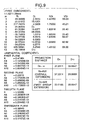
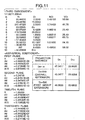
- m represents a plane number for a lens plane which is counted from the screen 21 side (long conjugate side)
- ri represents an i-th radius of curvature which is counted from the screen side
- di represents an i-th lens spacing
- ni represents an i-th refractive index
- vi represents i-th Abbe number.
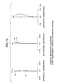
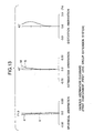
- the lens spacing in each of Figs. 9, 10 and 11 is shown for the case where the overall extension system is used as the focus adjustment system and the case where the system for moving only the above first lens group 100 along the optical axis (which is described as "first group extension" in each group) is used.
- the plane shape as the aspherical plane of the first plane, the second plane, the twelfth plane and the thirteenth plane is represented by the following equation wherein the center of the plane is set as an origin, r represents the central radius of curvature, k represents a cone coefficient and A4, A6, A8, A10 represent 4-order, 6-order, 8-order and 10-order aspherical plane coefficients, respectively.
- the spherical aberration, the astigmatism and the distortion aberration for the projection lenses 20 of the first to third embodiments are compared between the case where the overall extension system is used as the focus adjustment system and the case where the system of moving only the first lens group 100 along the optical axis (first lens group extension system) is used.
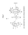
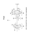
- the actual structure of the projection lens as the first to third embodiments is not limited to those shown in Figs. 6 to 8, and the number of lenses constituting each lens group may be changed insofar as the conditions described above are satisfied.
- the projection lens of the present invention is equipped in a projection device in which a liquid crystal panel is used as a two-dimensional image display element in a back projection type projection display device, however, the present invention is not limited to these embodiments.
- the present invention may be applied to a wide-angle photograph lens for a single-lens camera, a projection lens for a projection television using CRT, etc.
Landscapes
- Physics & Mathematics (AREA)
- Engineering & Computer Science (AREA)
- Multimedia (AREA)
- Signal Processing (AREA)
- General Physics & Mathematics (AREA)
- Optics & Photonics (AREA)
- Projection Apparatus (AREA)
- Lenses (AREA)
- Liquid Crystal (AREA)
Applications Claiming Priority (2)
| Application Number | Priority Date | Filing Date | Title |
|---|---|---|---|
| JP10115204A JPH11305117A (ja) | 1998-04-24 | 1998-04-24 | 投射レンズ及び投射レンズの焦点調整方法 |
| JP11520498 | 1998-04-24 |
Publications (3)
| Publication Number | Publication Date |
|---|---|
| EP0952474A2 EP0952474A2 (en) | 1999-10-27 |
| EP0952474A3 EP0952474A3 (en) | 2001-10-17 |
| EP0952474B1 true EP0952474B1 (en) | 2003-11-12 |
Family
ID=14656942
Family Applications (1)
| Application Number | Title | Priority Date | Filing Date |
|---|---|---|---|
| EP99303114A Expired - Lifetime EP0952474B1 (en) | 1998-04-24 | 1999-04-22 | Projection lens and focus adjusting method for projection lens |
Country Status (7)
| Country | Link |
|---|---|
| US (1) | US6144503A (enExample) |
| EP (1) | EP0952474B1 (enExample) |
| JP (1) | JPH11305117A (enExample) |
| KR (1) | KR100591782B1 (enExample) |
| CA (1) | CA2269484C (enExample) |
| DE (1) | DE69912674T2 (enExample) |
| ES (1) | ES2209331T3 (enExample) |
Families Citing this family (43)
| Publication number | Priority date | Publication date | Assignee | Title |
|---|---|---|---|---|
| JP2001343706A (ja) * | 2000-05-31 | 2001-12-14 | Sony Corp | 映像表示装置 |
| JP4224938B2 (ja) * | 2000-10-17 | 2009-02-18 | コニカミノルタオプト株式会社 | 斜め投影光学系 |
| JP2003015033A (ja) | 2001-06-28 | 2003-01-15 | Minolta Co Ltd | 投射光学系 |
| KR100542760B1 (ko) * | 2001-07-31 | 2006-01-20 | 엘지전자 주식회사 | 프로젝션 시스템의 투사렌즈계 |
| EP1422543A4 (en) * | 2001-08-28 | 2005-06-29 | Sony Corp | PROJECTION LENS |
| KR100441591B1 (ko) * | 2002-07-02 | 2004-07-23 | 삼성전자주식회사 | 영상투사장치의 투사렌즈계 |
| US7175287B2 (en) * | 2002-08-16 | 2007-02-13 | Infocus Corporation | Wide angle projection lens |
| US7009765B2 (en) * | 2002-08-16 | 2006-03-07 | Infocus Corporation | Wide angle lens system having a distorted intermediate image |
| US6896375B2 (en) * | 2002-08-16 | 2005-05-24 | Infocus Corporation | Rear projection display device having multiple mirrors that are substantially parallel to a screen |
| US7150537B2 (en) * | 2002-08-16 | 2006-12-19 | Infocus Corporation | Projection television device and screen |
| US7102820B2 (en) * | 2002-08-16 | 2006-09-05 | Infocus Corporation | Flat valley fresnel lens for a display device |
| US7341353B2 (en) * | 2002-08-16 | 2008-03-11 | Infocus Corporation | Variable fresnel screen for use in projection device |
| US6853493B2 (en) | 2003-01-07 | 2005-02-08 | 3M Innovative Properties Company | Folded, telecentric projection lenses for use with pixelized panels |
| US6765731B1 (en) | 2003-03-28 | 2004-07-20 | 3M Innovative Properties Company | Low element count projection lenses for use with pixelized panels |
| JP2004326079A (ja) * | 2003-04-10 | 2004-11-18 | Seiko Epson Corp | 投射レンズ及び投写型画像表示装置 |
| JP2004354437A (ja) * | 2003-05-27 | 2004-12-16 | Fuji Photo Optical Co Ltd | リアプロジェクション装置 |
| US7080910B2 (en) * | 2003-08-19 | 2006-07-25 | Infocus Corporation | Method and system for a thermal architecture and user adjustable keystone in a display device |
| JP4196815B2 (ja) * | 2003-11-28 | 2008-12-17 | 株式会社日立製作所 | 背面投写型映像表示装置 |
| EP1698182A1 (en) * | 2003-12-16 | 2006-09-06 | Koninklijke Philips Electronics N.V. | Rotatable projection lens for rear-projection applications |
| US7259912B2 (en) | 2004-01-06 | 2007-08-21 | Infocus Corporation | Fresnel lens having reduced distortions |
| JP4333401B2 (ja) | 2004-02-19 | 2009-09-16 | セイコーエプソン株式会社 | 小型ズームレンズ |
| US7116498B2 (en) * | 2004-03-12 | 2006-10-03 | Sony Corporation | Projection optical system and image projection apparatus |
| WO2005124419A1 (ja) * | 2004-06-17 | 2005-12-29 | Nikon Corporation | プロジェクターレンズ及びこのプロジェクターレンズを用いたプロジェクター装置 |
| JP2006047948A (ja) * | 2004-06-29 | 2006-02-16 | Konica Minolta Opto Inc | 投影光学系およびそれを備えた投影装置 |
| WO2006068363A1 (en) * | 2004-12-21 | 2006-06-29 | Lg Electronics Inc. | Thin type projector |
| KR100672506B1 (ko) * | 2004-12-22 | 2007-01-24 | 엘지전자 주식회사 | 프로젝터의 투사 장치 |
| JP4823641B2 (ja) * | 2005-10-19 | 2011-11-24 | 富士フイルム株式会社 | 投写レンズおよびこれを用いた投写型表示装置 |
| JP2007225776A (ja) * | 2006-02-22 | 2007-09-06 | Konica Minolta Opto Inc | 画像投影装置 |
| TWI284747B (en) * | 2006-05-18 | 2007-08-01 | Young Optics Inc | Fixed-focus lens |
| KR100862013B1 (ko) | 2007-01-23 | 2008-10-07 | 정승태 | 렌즈를 사용하는 광학장치의 결상면 밝기 보정용 필터 |
| JP2008203604A (ja) * | 2007-02-21 | 2008-09-04 | Hitachi Ltd | 投射型映像表示装置 |
| TW200903026A (en) * | 2007-07-12 | 2009-01-16 | Young Optics Inc | Fixed-focus lens |
| US7605988B2 (en) * | 2007-07-23 | 2009-10-20 | Angstrom, Inc. | Compact image taking lens system with a lens-surfaced prism |
| JP5009726B2 (ja) * | 2007-09-03 | 2012-08-22 | 富士フイルム株式会社 | 投影レンズおよびこれを用いた投写型表示装置 |
| US20090185067A1 (en) * | 2007-12-21 | 2009-07-23 | Stereo Display, Inc. | Compact automatic focusing camera |
| JP5358280B2 (ja) * | 2009-05-12 | 2013-12-04 | 日立コンシューマエレクトロニクス株式会社 | 投写ボード装置、及びこれに用いる透過型スクリーン |
| KR20110120590A (ko) * | 2010-04-29 | 2011-11-04 | 삼성전자주식회사 | 광학 시스템 및 이를 적용한 영상투사장치 |
| TWI427323B (zh) * | 2011-02-18 | 2014-02-21 | Young Optics Inc | 投影鏡頭與投影裝置 |
| JP5652349B2 (ja) * | 2011-07-25 | 2015-01-14 | 株式会社リコー | 広角レンズおよび全天球型撮像装置 |
| CN103439783B (zh) * | 2011-11-15 | 2017-09-12 | 深圳市亿思达科技集团有限公司 | 一种高分辩率广角投影镜头及投影仪 |
| JP5487251B2 (ja) * | 2012-07-06 | 2014-05-07 | 日立コンシューマエレクトロニクス株式会社 | 投写型映像表示装置および投写光学ユニット |
| US10746994B2 (en) * | 2014-08-07 | 2020-08-18 | Microsoft Technology Licensing, Llc | Spherical mirror having a decoupled aspheric |
| TWI614517B (zh) | 2017-01-04 | 2018-02-11 | 大立光電股份有限公司 | 影像擷取系統、取像裝置及電子裝置 |
Family Cites Families (9)
| Publication number | Priority date | Publication date | Assignee | Title |
|---|---|---|---|---|
| US4526442A (en) * | 1981-01-28 | 1985-07-02 | U.S. Precision Lens, Inc. | Compact projection lens |
| DE3119993A1 (de) * | 1981-05-20 | 1982-12-16 | Rolf Dr.-Ing. 7888 Rheinfelden Müller | "weitwinkelobjektiv" |
| US5278698A (en) * | 1990-07-06 | 1994-01-11 | Asahi Kogaku Kogyo Kabushiki Kaisha | Magnifying projecting lens |
| JPH04174812A (ja) * | 1990-11-08 | 1992-06-23 | Canon Inc | レトロフォーカス型レンズ |
| US5390048A (en) * | 1991-12-02 | 1995-02-14 | Matsushita Electric Industrial Co., Ltd. | Projection lens assembly and projection display apparatus |
| US5296967A (en) * | 1992-03-02 | 1994-03-22 | U.S. Precision Lens Incorporated | High speed wide angle projection TV lens system |
| JP3433266B2 (ja) * | 1993-06-15 | 2003-08-04 | 三菱電機株式会社 | 投写レンズ |
| KR100210247B1 (ko) * | 1996-01-24 | 1999-07-15 | 윤종용 | 광화각 액정 프로젝션 렌즈 시스템 |
| US5870228A (en) * | 1996-05-24 | 1999-02-09 | U.S. Precision Lens Inc. | Projection lenses having larger back focal length to focal length ratios |
-
1998
- 1998-04-24 JP JP10115204A patent/JPH11305117A/ja active Pending
-
1999
- 1999-04-20 US US09/294,380 patent/US6144503A/en not_active Expired - Fee Related
- 1999-04-21 CA CA002269484A patent/CA2269484C/en not_active Expired - Fee Related
- 1999-04-22 KR KR1019990014446A patent/KR100591782B1/ko not_active Expired - Fee Related
- 1999-04-22 EP EP99303114A patent/EP0952474B1/en not_active Expired - Lifetime
- 1999-04-22 DE DE69912674T patent/DE69912674T2/de not_active Expired - Fee Related
- 1999-04-22 ES ES99303114T patent/ES2209331T3/es not_active Expired - Lifetime
Also Published As
| Publication number | Publication date |
|---|---|
| KR19990083411A (ko) | 1999-11-25 |
| DE69912674T2 (de) | 2004-09-23 |
| CA2269484C (en) | 2007-10-09 |
| ES2209331T3 (es) | 2004-06-16 |
| EP0952474A2 (en) | 1999-10-27 |
| EP0952474A3 (en) | 2001-10-17 |
| DE69912674D1 (de) | 2003-12-18 |
| CA2269484A1 (en) | 1999-10-24 |
| JPH11305117A (ja) | 1999-11-05 |
| KR100591782B1 (ko) | 2006-06-23 |
| US6144503A (en) | 2000-11-07 |
Similar Documents
| Publication | Publication Date | Title |
|---|---|---|
| EP0952474B1 (en) | Projection lens and focus adjusting method for projection lens | |
| US7190528B2 (en) | Zoom lens and image projection apparatus having the same | |
| JP3982363B2 (ja) | 投射レンズ、プロジェクション表示装置 | |
| US5168351A (en) | Short focal length video color projector employing dichroic mirror block | |
| US6937401B2 (en) | Projection lens | |
| JPH09218379A (ja) | 広画角液晶プロジェクションレンズシステム | |
| JPH08320433A (ja) | 広角レンズ | |
| EP0602732A2 (en) | Optical system with astigmatism compensation | |
| US7667898B2 (en) | Zoom lens and projector | |
| EP1058461A2 (en) | Colour image projector | |
| US20050185153A1 (en) | Wide angle-of-view and high resolution rear projection optical system | |
| JP2002229125A (ja) | 投射型画像表示装置および画像表示システム | |
| US6590714B2 (en) | Color combining optical system and projection type display apparatus having the same | |
| US11061308B2 (en) | Projection optical system and projector | |
| US5539580A (en) | Projection optical system for a liquid crystal projector | |
| EP1014159B1 (en) | Illumination apparatus and projection apparatus | |
| KR100531383B1 (ko) | 프로젝션 시스템의 초 광각 줌 렌즈 | |
| KR100542760B1 (ko) | 프로젝션 시스템의 투사렌즈계 | |
| JP2000171703A (ja) | 投射レンズ | |
| JPH11305116A (ja) | 投射レンズ | |
| JP2003195164A (ja) | 広角投射レンズ及び広角投射レンズを用いた投射型表示装置 | |
| JPH11326763A (ja) | ズームレンズ及びそれを用いた投影装置 | |
| JP2000171702A (ja) | 投射レンズ | |
| JP2003066329A (ja) | 投射レンズ、及び映像表示装置 | |
| KR100385885B1 (ko) | 프로젝터용 투사광학계 |
Legal Events
| Date | Code | Title | Description |
|---|---|---|---|
| PUAI | Public reference made under article 153(3) epc to a published international application that has entered the european phase |
Free format text: ORIGINAL CODE: 0009012 |
|
| AK | Designated contracting states |
Kind code of ref document: A2 Designated state(s): AT BE CH CY DE DK ES FI FR GB GR IE IT LI LU MC NL PT SE Kind code of ref document: A2 Designated state(s): DE ES FR GB |
|
| AX | Request for extension of the european patent |
Free format text: AL;LT;LV;MK;RO;SI |
|
| PUAL | Search report despatched |
Free format text: ORIGINAL CODE: 0009013 |
|
| AK | Designated contracting states |
Kind code of ref document: A3 Designated state(s): AT BE CH CY DE DK ES FI FR GB GR IE IT LI LU MC NL PT SE |
|
| AX | Request for extension of the european patent |
Free format text: AL;LT;LV;MK;RO;SI |
|
| 17P | Request for examination filed |
Effective date: 20020320 |
|
| AKX | Designation fees paid |
Free format text: DE ES FR GB |
|
| GRAH | Despatch of communication of intention to grant a patent |
Free format text: ORIGINAL CODE: EPIDOS IGRA |
|
| GRAS | Grant fee paid |
Free format text: ORIGINAL CODE: EPIDOSNIGR3 |
|
| GRAA | (expected) grant |
Free format text: ORIGINAL CODE: 0009210 |
|
| AK | Designated contracting states |
Kind code of ref document: B1 Designated state(s): DE ES FR GB |
|
| REG | Reference to a national code |
Ref country code: GB Ref legal event code: FG4D |
|
| REF | Corresponds to: |
Ref document number: 69912674 Country of ref document: DE Date of ref document: 20031218 Kind code of ref document: P |
|
| REG | Reference to a national code |
Ref country code: ES Ref legal event code: FG2A Ref document number: 2209331 Country of ref document: ES Kind code of ref document: T3 |
|
| ET | Fr: translation filed | ||
| PLBE | No opposition filed within time limit |
Free format text: ORIGINAL CODE: 0009261 |
|
| STAA | Information on the status of an ep patent application or granted ep patent |
Free format text: STATUS: NO OPPOSITION FILED WITHIN TIME LIMIT |
|
| 26N | No opposition filed |
Effective date: 20040813 |
|
| PGFP | Annual fee paid to national office [announced via postgrant information from national office to epo] |
Ref country code: ES Payment date: 20090508 Year of fee payment: 11 |
|
| PGFP | Annual fee paid to national office [announced via postgrant information from national office to epo] |
Ref country code: FR Payment date: 20090417 Year of fee payment: 11 Ref country code: DE Payment date: 20090420 Year of fee payment: 11 |
|
| PGFP | Annual fee paid to national office [announced via postgrant information from national office to epo] |
Ref country code: GB Payment date: 20090422 Year of fee payment: 11 |
|
| GBPC | Gb: european patent ceased through non-payment of renewal fee |
Effective date: 20100422 |
|
| REG | Reference to a national code |
Ref country code: FR Ref legal event code: ST Effective date: 20101230 |
|
| PG25 | Lapsed in a contracting state [announced via postgrant information from national office to epo] |
Ref country code: DE Free format text: LAPSE BECAUSE OF NON-PAYMENT OF DUE FEES Effective date: 20101103 |
|
| PG25 | Lapsed in a contracting state [announced via postgrant information from national office to epo] |
Ref country code: GB Free format text: LAPSE BECAUSE OF NON-PAYMENT OF DUE FEES Effective date: 20100422 |
|
| REG | Reference to a national code |
Ref country code: ES Ref legal event code: FD2A Effective date: 20110718 |
|
| PG25 | Lapsed in a contracting state [announced via postgrant information from national office to epo] |
Ref country code: ES Free format text: LAPSE BECAUSE OF NON-PAYMENT OF DUE FEES Effective date: 20110706 |
|
| PG25 | Lapsed in a contracting state [announced via postgrant information from national office to epo] |
Ref country code: ES Free format text: LAPSE BECAUSE OF NON-PAYMENT OF DUE FEES Effective date: 20100423 |
|
| PG25 | Lapsed in a contracting state [announced via postgrant information from national office to epo] |
Ref country code: FR Free format text: LAPSE BECAUSE OF NON-PAYMENT OF DUE FEES Effective date: 20100430 |