EP0951189B1 - Dualband tragbares Telefon, umschaltbar zwischen unterschiedlichen Telefonsystemen - Google Patents
Dualband tragbares Telefon, umschaltbar zwischen unterschiedlichen Telefonsystemen Download PDFInfo
- Publication number
- EP0951189B1 EP0951189B1 EP99106195A EP99106195A EP0951189B1 EP 0951189 B1 EP0951189 B1 EP 0951189B1 EP 99106195 A EP99106195 A EP 99106195A EP 99106195 A EP99106195 A EP 99106195A EP 0951189 B1 EP0951189 B1 EP 0951189B1
- Authority
- EP
- European Patent Office
- Prior art keywords
- mode
- mobile phone
- control channel
- portable phone
- dual band
- Prior art date
- Legal status (The legal status is an assumption and is not a legal conclusion. Google has not performed a legal analysis and makes no representation as to the accuracy of the status listed.)
- Expired - Lifetime
Links
- 230000009977 dual effect Effects 0.000 title claims description 81
- 238000000034 method Methods 0.000 claims description 52
- 238000004891 communication Methods 0.000 claims description 27
- 230000004044 response Effects 0.000 claims description 17
- 238000012508 change request Methods 0.000 claims description 12
- 230000005684 electric field Effects 0.000 claims description 7
- 230000008569 process Effects 0.000 description 33
- 238000010586 diagram Methods 0.000 description 3
- 238000005516 engineering process Methods 0.000 description 3
- 230000001413 cellular effect Effects 0.000 description 2
- 230000003247 decreasing effect Effects 0.000 description 2
- 230000009471 action Effects 0.000 description 1
- 238000010276 construction Methods 0.000 description 1
- 230000006870 function Effects 0.000 description 1
- 230000000977 initiatory effect Effects 0.000 description 1
- 238000010295 mobile communication Methods 0.000 description 1
- 230000005236 sound signal Effects 0.000 description 1
Images


Classifications
-
- H—ELECTRICITY
- H04—ELECTRIC COMMUNICATION TECHNIQUE
- H04W—WIRELESS COMMUNICATION NETWORKS
- H04W88/00—Devices specially adapted for wireless communication networks, e.g. terminals, base stations or access point devices
- H04W88/02—Terminal devices
- H04W88/06—Terminal devices adapted for operation in multiple networks or having at least two operational modes, e.g. multi-mode terminals
Definitions
- the present invention relates to a dual band portable phone, and more particularly to a technique for quickly switching from one mobile phone system to another and a method for the same.
- a PHS personal handyphone system
- a mobile phone system employs a cellular technology in which an area size where electromagnetic wave can be received is up to about 100 meters radially from the base station of each cell. Therefore, it is essential to provide many base stations for a wide service area. While the PHS system is less in service fee than any other mobile phone systems, it is sometimes difficult to receive the electromagnetic wave.
- a GSM global system for mobile communications
- the GSM system is however higher in the service fee than the PHS system.
- the dual band portable phone operable in both the PHS system and the GSM system.
- the dual band portable phone usually operates in the PHS mode.
- the portable phone When being moved out of the service area for the PHS mode, the portable phone starts operating using the GSM mode.
- the PHS mode is a mode where the dual band portable phone is used as a mobile station of the PHS system
- the GSM mode is a mode where the same is used as a mobile station of the GSM system.
- the dual band portable phone When the dual band portable phone is turned on, it starts a function for searching the control channel in either the PHS system or the GSM system.
- the channel number (frequency) of the control channel is assigned to each dual band portable phone by a service supplier (an operator) of the PHS system.
- the dual band portable phone has a built-in memory in which the channel number is registered such that the control channel of the PHS system can be quickly found.
- the channel number of the control channel may arbitrarily be determined by its operator when desired. This requires the dual band portable phone to search a desired control channel through checking all the available channels for registration of the position. When the dual band portable phone is moved from the service area of the PHS system to the service area of the GSM system, it has to search all the available channels to determine the control channel to be used during the searching action.
- a related technology is disclosed as "method of registering the position in mobile radio communication" in Japanese Laid Open Patent Application ( JP-A-Showa 63-203025 ).
- the method of registering the position in mobile radio communication involves registering the position of a mobile portable phone when it is moved from one cell to another in the mobile phone system. More particularly, while a single control channel is used commonly in different systems, both automatic position registration and manual position registration are enabled.
- JP-A-Showa 63-203025 no technique is disclosed for allowing the mobile portable phone to move between the service areas of different mobile phone systems.
- radio communications apparatus and method of radio communications is disclosed in Japanese Laid Open Patent Application ( JP-A-Heisei 9-51321 ).
- the reference describes a technology for allocating frequency bands to two communication systems (for CDMA and cordless-telephone).
- a technique is not indicated to quickly perform a position registering process when the portable phone is moved between the service areas of the different mobile phone systems.
- DE 4344702 A1 discloses a dual band mobile phone which can communicate both over a GSM and over a PHS system. The incoming calls are routed automatically over the available system. When the PHS system is unavailable for longer periods, the phone searches for the availability of the GSM system.
- CMTS/MCS compatible mobile portable phone is disclosed in Japanese Laid Open Patent Application ( JP-A-Heisei 5-102923 ).
- the CMTS/MCS compatible mobile portable phone operates in either of a CMTS mode and an MCS mode when it is turned on.
- the CMTS/MCS compatible mobile portable phone cannot switch from its dedicated mobile phone system to another mobile phone system when it is moved out of the service area of the dedicated mobile phone system and its communication is disabled.
- An object of the present invention is to eliminate the foregoing disadvantages of conventional mobile telephones.
- Another object is to provide a dual band portable phone capable of quickly performing a position registering process for another mobile phone system when the portable phone is moved out of a service area of the current mobile phone system.
- Still another object of the present invention is to provide a method of switching between different mobile phone systems.
- a dual band portable phone includes a first mobile phone system used in a first mode, a second mobile phone system used in a second mode, a storing section and a control section.
- the storing section has a mode area for storing a mode data indicative of a current operation mode, a first area for storing a first control channel data indicative of a first control channel used for the first mobile phone system in the first mode, and a second area for storing a second control channel data indicative of a second control channel used for the second mobile phone system in the second mode.
- the mode data indicates the first mode at present.
- the control section performs a position registration of the portable phone using the second control channel data stored in the storing section to set the second mode, when a first radio communication using the first mobile phone system becomes impossible while the first radio communication is performed in the first mode.
- the control section also performs a second radio communication using the second mobile phone system.
- the control section may perform the position registration of the portable phone using the second control channel data stored in the storing section to set the second mode, when the portable phone is moved out of a first service area of the first mobile phone system while the first radio communication is performed in the first mode.
- control section may transmit a position registration request to a station for the second mobile phone system using the second control channel data, and may set the mode data indicative of the second mode in the storing section in response to a position registration completion notice from the station to set the second mode.
- control section may perform a position registration of the portable phone using the first control channel data stored in the storing section in response to a mode change request while the second radio communication is performed in the second mode, set the first mode in response to the position registration of the portable phone using the first control channel data, and perform a radio communication using the first mobile phone system.
- the mode change request may be issued when the portable phone is moved out of a service area of the second mobile phone system and into a service area of the first mobile phone system.
- the mode change request may be issued when the portable phone is located in a service area of the second mobile phone system and is moved into a service area of the first mobile phone system.
- the mode change request may be issued when the portable phone is located in a service area of the first mobile phone system and an operation unit is operated.
- control section acquires the first control channel data and the second control channel data in response to a start request, to store in the storing section.
- the start request may be issued when a power supply of the portable phone is turned on.
- control section sets the mode data indicative of the first mode in the storing section when both of the first control channel data and the second control channel data are acquired or when the first control channel data is acquired.
- the control section sets the mode data indicative of the second mode in the storing section when the second control channel data is acquired and when the first control channel data is not acquired.
- control section selects one having the highest reception electric field intensity level from among control channels for each of the first and second mobile phone systems to store a data corresponding to the one having the highest reception electric field intensity level in the storing section.
- the first mobile phone system is a PHS system and a second mobile phone system is a GSM system.
- a method of performing communication in a dual band portable phone includes:
- a PHS system is assigned as a first mobile phone system and a GSM system is assigned as a second mobile phone system.
- the dual band portable phone is located at a position where the service areas of two different mobile phone systems, namely the PHS system and the GSM system, overlap each other.
- the dual band portable phone carries out registration of its position for the PHS system and saves the channel numbers of the control channels of the GSM system in its memory, when the control channels of their respective mobile phone systems are searched.
- the dual band portable phone uses the control channel corresponding to the channel number stored in the memory. Accordingly, no time for searching the control channel is required, so that the registration of the position of the dual band portable phone to the base station in the GSM system can readily be conducted.
- Fig. 1 is a block diagram showing a structure of the dual band portable phone of the present invention.
- the dual band portable phone is composed of a common antenna 1, a PHS radio section 2, a GSM radio section 3, a common control section 4, a memory section 5, a speaker 6, a microphone 7, a key entry 8, and a display section 9.
- the common antenna 1 emits into the air, electromagnetic wave converted from an electric signal supplied from the PHS radio section 2 or the GSM radio section 3.
- the common antenna 1 also converts electromagnetic waves received from a PHS base station and a GSM base station both (not shown) into electric signals. The converted electric signal is then supplied to the PHS radio section 2 and the GSM radio section 3.
- the PHS radio section 2 modulates a data outputted from the common control section 4 to the common antenna 1. Also, the PHS radio section 2 demodulates the electric signal received by the common antenna 1. The demodulated electric signal is supplied as a reception data to the common control section 4. Similarly, the GSM radio section 3 modulates a data outputted from the common control section 4 to the common antenna 1 into an electric signal. Also, the GSM radio section 3 demodulates an electric signal received from the common antenna 1. The demodulated electric signal is supplied as a reception data to the common control section 4.
- the common control section 4 controls the entirety of the dual band portable phone.
- the common control section 4 may be a microprocessor.
- the memory section 5 stores therein programs to be executed as well as various data.
- the common control section 4 executes the programs stored in the memory section 5 to control the operation of the dual band portable phone.
- the memory section 5 includes a mode storage section 50, a PHS control channel storage section 51 and a GSM control channel storage section 52.
- the mode storage section 50 stores the current operation mode of the dual band portable phone.
- the PHS control channel storage section 51 stores the channel number of a PHS control channel.
- the GSM control channel storage section 52 stores the channel number of a GSM control channel. It is noted that a channel number of the PHS control channel predetermined by the operator is saved in the PHS control channel storage section 51.
- the speaker 6 emits a voice sound corresponding to an audio signal supplied from the common control section 4.
- the microphone 7 converts a voice sound into an electric signal which is supplied to the common control section 4.
- the key operation section 8 has, for example, a power switch (not shown) for turning on the power supply, a ten-key pad for inputting a dial number, and other controls (not shown).
- the display section 9 may be an LCD for displaying a symbol indicative of the out-of-area/in-area states, date, time, electric field intensity of the received electromagnetic wave, dial numbers, and other messages.
- the GSM base station (GSM CS) 11 covers a GSM service area 12 while the PHS base station (PHS CS) 13 covers a PHS service area 14.
- the dual band portable phone 10 is about to be moved from a position A where the GSM service area 12 and the PHS service area 14 overlap each other, to a position B which is in the GSM service area 12 but out of the PHS service area 14.
- the operation of the dual band portable phone is as follows.
- the dual band portable phone 10 When the dual band portable phone 10 is powered on at the position A, it receives the control channels from both the GSM base station 11 and the PHS base station 13. At this time, the dual band portable phone 10 registers its position to the PHS base station 13 and saves the channel number of the GSM control channel in the GSM control channel storage section 52 of its memory section 5.
- the dual band portable phone 10 is moved from the position A to the position B, it is disabled to receive the control channel of the PHS base station 13.
- the common control section 4 reads out the channel number from the GSM control channel storage section 52 of the memory section 5 and registers the position to the GSM base station 11 using the control channel corresponding to the channel number.
- the initial process will be described with reference to the flowchart shown in Fig. 3 .
- the routine of the initial process is initiated when the power supply is turned on. More specifically, when a power switch on the key operation section 8 is operated, a start request signal is issued at the same time as the power supply is turned on.
- a PHS position registration process is carried out in response to the start request (Step S10).
- PHS position registration process registration its position to the PHS base station 13 is performed when the dual band portable phone 10 is located in the PHS service area 14, as will be described later in more detail.
- its operation mode is set to the PHS mode. If the dual band portable phone 10 is out of the PHS service area 14, its operation mode remains unchanged so that a display section displays the PHS out-of-area state.
- Step S11 the GSM position registration
- the channel number indicative of a control channel is searched and stored in the GSM control channel storage section 52 of the memory section 5, as will be described later in more detail.
- the dual band portable phone 10 is not set to the PHS mode and located in the GSM service area 12, its position is registered to the GSM base station 11 and its operation mode is set to the GSM mode.
- the dual band portable phone 10 is not set to the PHS mode and located out of the GSM service area 12, its operation mode remains unchanged so that the display section displays the GSM out-of-area state.
- Step S12 It is then checked whether or not the dual band portable phone 10 is in the PHS mode (Step S12).
- the control goes to the PHS standby state (Step S13).
- PHS standby state a broadcast calling channel (PCH) transmitted from the PHS base station 13 in a predetermined interval of one or two seconds can be received.
- PCH broadcast calling channel
- Step S14 When it is determined that the phone 10 is out of the PHS service area 14, it is checked whether or not the dual band portable phone 10 is set to the GSM mode (Step S14). When it is determined that the dual band portable phone 10 stays in the GSM service area 12, the control goes to the GSM standby state (Step S15). In the GSM standby state, a broadcast calling channel (PCH) emitted in a predetermined interval of one or two seconds from the GSM base station 11 can be received. When it is determined that the phone 10 is out of the GSM service area 12, the power is turned off (Step S16).
- PCH broadcast calling channel
- the dual band portable phone 10 registers its position to the PHS base station 13 if the position registration is possible and is also set to the PHS mode. This allows the dual band portable phone 10 to be used in the PHS mode.
- the channel number of the GSM control channel is saved in the GSM control channel storage section 52 of the memory section 5.
- the position registration to the PHS base station 13 is impossible and the position registration to the GSM base station 11 is possible, the position is registered to the GSM base station 11 and the operation mode is switched to the GSM mode.
- the channel number of the GSM control channel is saved in the GSM control channel storage section 52 of the memory section 5.
- the dual band portable phone 10 is out of the operation so that its power supply is turned off.
- the PHS position registration carried out at Step S10 will be described in more detail referring to the flowchart shown in Fig. 4 .
- the routine of the PHS position registration is called at Step S10 of the initial process routine.
- the channel number of the control channel (CcH) is stored in the PHS control channel storage section 51 of the memory section 5.
- the common control section 4 instructs the PHS radio section 2 to continuously receive a signal for a period of, e.g., 300 ms (Step S20). More particularly, the common control section 4 controls the PHS radio section 2 to turn up the frequency of the control channel corresponding to the channel number stored in the PHS control channel storage section 51. Then, the PHS radio section 2 demodulates the received signal. The demodulated signal is supplied to the common control section 4.
- the common control section 4 checks whether or not electromagnetic wave of the control channel is received during the period of 300 ms (Step S21). When it is determined that the control channel electromagnetic wave is not received, the PHS out-of-area state is displayed (Step S28). In practice, the common control section 4 supplies the display section 9 with a predetermined data. Then, the display section 9 displays a message or a symbol indicating that the phone 10 is out of the PHS service area 14. Then, the control returns back to Step S11 of the initial process routine.
- Step S21 When it is determined that the control channel is received at Step S21, it is checked whether the reception electric field intensity level (RSSI) of the control channel is greater than a threshold value predetermined in the system, i.e., 40 dB ⁇ V/m (Step S22). When it is determined that the control channel electromagnetic wave having a field level greater than the threshold value is not received, the control jumps to Step S28 such that the PHS out-of-area state is displayed.
- RSSI reception electric field intensity level
- Step S22 When it is determined at Step S22 that one or more control channel electromagnetic waves having field levels greater than the threshold value are received, a process is performed to select the optimum control channel (Step S23). As the plural control channel electromagnetic waves having a field levels greater than the threshold value have been received, they are allocated with priority levels in the order of larger field level. The control channel electromagnetic wave having the highest priority is selected as the optimum control channel.
- the position registration request is issued (Step S24). That is, the common control section 4 transmits the position registration request to the PHS base station 13 which has transmitted the optimum control channel. More specifically, the position registration request is sent from the common control section 4 to the PHS radio section 2, is modulated and amplified by the PHS radio section 2, and then transmitted via the common antenna 1 to the PHS base station 13. It is then examined whether the position registration is completed or not (Step S25). This process is implemented by checking whether a data indicative of the completion of the position registration has been received from the PHS base station 13.
- the operation mode of the dual band portable phone 10 is set to the PHS mode (Step S26). More particularly, data of the PHS mode is saved in the PHS control channel storage section 51 of the memory section 5. Then, the control returns back to Step S11 of the initial process routine.
- Step S25 When it is determined at Step S25 that the position registration is not completed, i.e. the data of completion of the position registration is not properly received from the PHS base station 13, it is checked whether the other control channels are present (Step S27). In other words, it is examined whether control channel electromagnetic wave having the second highest priority is available or not. When it is determined that the control channel electromagnetic wave having the second highest priority level is available, the control channel electromagnetic wave having the second highest priority is selected as the optimum control channel. Then, the control goes back to Step S24. The position registration request as described above is issued to the PHS base station 13 which has transmitted the control channel electromagnetic wave having the second highest priority. When it is determined at Step S27 that the other control channels are not available, the control advances to Step S28 for display of the PHS out-of-area state.
- Steps S24, S25, S27, S24, and so on a group of the control channels are examined whether or not the position can be registered to the corresponding PHS base station 13. As a result, the control channel corresponding to the highest priority level is registered in the PHS base station 13. When non of the PHS base stations 13 is available for the position registration, the PHS out-of-area state is displayed.
- Step S11 The GSM position registration carried out at Step S11 will be now described in more detail with reference to the flowchart shown in Fig. 5 .
- the routine of the GSM position registration is called at Step S11 of the initial process routine.
- the channel number of the control channel has not been determined in advance but arbitrarily determined by the operator or the GSM base station 11.
- a process of checking all the control channels is performed. The following description is made in respect of the aspects distinguished from those of the PHS mode.
- Step S30 a process of checking all the control channels is performed (Step S30). More specifically, the common control section 4 controls the GSM radio section 3 to sequentially tune up frequencies corresponding to all the channel numbers. The GSM radio section 3 demodulates the received signals. The resultant demodulated signal is supplied to the common control section 4. Then, the common control section 4 examines whether or not the control channel electromagnetic wave is received (Step S31).
- Step S40 When it is determined that the control channel electromagnetic wave is not received, the control jumps to Step S40 for display of the GSM out-of-area state (Step S40). More particularly, the common control section 4 sends a predetermined data to the display section 9 which in turn displays a message or a symbol indicating that the phone 10 is out of the GSM service area 12. The control then returns back to Step S12 of the initial process routine.
- Step S31 When it is determined at Step S31 that the control channel electromagnetic wave is received, it is checked whether the reception electric field intensity level (RSSI) of the control channel electromagnetic wave is greater than a threshold value determined by the system (Step S32). When it is determined that the control channel electromagnetic wave having a field level greater than the threshold value is not received, the control jumps to Step S40 for display of the GSM out-of-area state.
- RSSI reception electric field intensity level
- Step S33 When it is determined at Step S32 that one or more control channel electromagnetic waves having field levels greater than the threshold value are received, the selection of the optimum control channel is carried out (Step S33). As the control channel electromagnetic waves having field levels greater than the threshold value have been received, they are allocated with priority levels in the order of their field level. Accordingly, the control channel with the highest priority is selected as the optimum control channel.
- the channel numbers of all the control channels are stored in the GSM control channel storage section 52 of the memory section 5 (Step S34).
- the channel numbers stored in the GSM control channel storage section 52 are referred when the operation mode of the dual band portable phone 10 or the mobile phone system is switched to another system.
- Step S35 it is then examined whether the current mode is the PHS mode or not (Step S35). This step is implemented by checking the mode data of the current operation mode stored in the mode storage section 50 of the memory section 5. When it is found that the current mode is the PHS mode, it is recognized that the PHS position registration has been conducted. Therefore, the control goes back to Step S12 of the initial process routine without carrying out the GSM position registration starting from Step S36.
- Step S35 When it is determined at Step S35 that the current operation mode is not the PHS mode, it is recognized that the PHS position registration has not yet been conducted. Therefore, the GSM position registration starting from Step S36 is carried out.
- the GSM position registration starts with a position registration request (Step S36). More particularly, the common control section 4 supplies the position registration request via the GSM radio section 3 to the GSM base station 11. In response, the GSM radio section 3 modulates, amplifies, and transmits the position registration request to the GSM base station 11 via the common antenna 1. Then, it is examined whether the position registration is completed or not (Step S37). This process is implemented by examining whether or not a data of completion of the position registration is properly received from the GSM base station 11.
- the operation mode of the dual band portable phone 10 is set to the GSM mode (Step S38). More specifically, a data indicative of the GSM mode is saved in the GSM control channel storage section 52 of the memory section 5. Then, the control returns back to Step S12 of the initial process routine.
- Step S39 When it is determined at Step S37 that the position registration is not completed, i.e. the data of completion of the position registration is not properly received from the GSM base station 11, it is checked whether another candidate of the control channel is present (Step S39). In other words, it is examined whether or not the other control channel electromagnetic wave having a priority level is received. When it is found that the other control channel is present, the control channel with the second highest priority is selected as the optimum control channel and the control goes back to Step S36. Then, the position registration request is issued to the GSM base station 11 which has transmitted the optimum control channel as described previously. On the other hand, when it is determined at Step S39 that the other control channel with priority level is not present, the control jumps to Step S40 for display of the GSM out-of-area state.
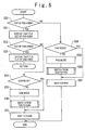
- the switching of the mobile phone system between the PHS system and the GSM system will be described in more detail with reference to the flowcharts shown in Figs. 6 and 7 .
- the routine of the mobile phone system switching is started in response to a mode switching request, i.e., a timer interrupt operation generated for every predetermined time interval by a timer (not shown).
- Step S50 it is checked whether or not the dual band portable phone 10 is out of the PHS service area 14, namely in its PHS out-of-area state.
- This step is implemented in the same manner as of the PHS position registration routine (See Fig. 4 ).
- the PHS out-of-area state is displayed (Step S51).
- the dual band portable phone 10 is out of the GSM service area 12, namely, in its GSM out-of-area state (Step S52).
- This step is implemented in the same manner as of the CSM position registration routine (See Fig. 5 ).
- the GSM out-of-area state is displayed (Step S53). The control then returns back to a step where the interruption is generated.
- Step S52 When it is determined at Step S52 that the portable phone 10 is in the GSM service area 12, it is checked whether the operation mode of the dual band portable phone 10 is the GSM mode (Step S54). When it is determined that the operation mode is not the GSM mode, it is recognized that the dual band portable phone 10 operating in the PHS mode has been move from the PHS area to the GSM area. As a result, the operation mode of the portable phone 10 is set to the GSM mode (Step S55).
- Step S56 a process of switching the mobile phone system from the PHS system to the GSM system is performed. This process will be described later in more detail.
- the dual band portable phone 10 enters a GSM standby mode (Step S57).
- Step S57 When it is determined at Step S54 that the operation mode is the GSM mode, it is recognized that the operation mode remains unchanged. As a result, the control jumps to Step S57 for calling the GSM standby mode.
- Step S50 When it is determined at Step S50 that the dual band portable phone 10 is in the PHS service area, it is checked whether the operation mode of the phone 10 is the PHS mode (Step S58). When it is determined that the operation mode is not the PHS mode, it is recognized that the dual band portable phone 10 operating in the GSM mode is moved into the PHS service area. As a result, the operation mode of the phone 10 is switched to the PHS mode (Step S59).
- Step S60 a process of switching the operation mode from the GSM mode to the PHS mode. This process is substantially the same as the operation of Step S56 (which will be described later in more detail) and its description will be omitted.
- Step S61 the dual band portable phone 10 enters a PHS standby mode.
- Step S58 it is determined at Step S58 that the operation mode is the PHS mode, it is recognized that the operation mode remains unchanged. Therefore, the control jumps to Step S61 for calling the PHS standby mode.
- Step S56 The switching of the mobile phone system from the PHS system to the GSM system carried out at Step S56 will be now described in more detail with reference to the flowchart shown in Fig. 7 .
- This switching process is performed in response to the mode switching request or the timer interrupt request, as described above.
- the common control section 4 checks whether or not the channel number of the GSM control channel is saved in the GSM control channel storage section 52 of the memory section 5 (Step S70). When it is determined that the channel number is saved, the common control section 4 controls the GSM radio section 3 to receive the control channel electromagnetic wave corresponding to by the channel number and subsequently searches the control channel (Step S71).
- Step S72 it is checked whether or not the GSM control channel electromagnetic wave corresponding to the channel number has been received correctly.
- the position registration is requested (Step S73). This process is the same as the process at Step S36.
- Step S74 it is examined whether the position registration is completed or not (Step S74). This step is the same as the process to Step S37.
- Step S78 When it is determined that the position registration is not completed, i.e. a data indicative of completion of the position registration is not received from the GSM base station 11, it is checked whether all the control channels have been checked for searching the GSM control channel (Step S78). When it is determined that all the control channels have not been checked, the control branches to Step S76 to check the remaining control channels. When it is determined that all the control channels have been checked, the control branches to Step S79 for display of the GSM out-of-area state (Step S79).
- Step S74 When it is determined at Step S74 that the position registration is completed, the channel number of the control channel at this time is saved in the GSM control channel storage section 52 of the memory section 5 (Step S75). Then, the control returns back to Step S57 (See Fig. 6 ) such that the dual band portable phone 10 enters the GSM standby mode. Accordingly, the routine of the mobile phone system switching is terminated.
- Step S76 When it is determined at Step S70 that the channel number is not saved in the GSM control channel storage section 52 of the memory section 5, all the control channels are checked (Step S76). This step is the same as that of Step S30. Subsequently, the common control section 4 checks whether a control channel electromagnetic wave is received on one of the control channel electromagnetic waves (Step S77).
- Step S79 When it is determined that the control channel electromagnetic wave is not received, the control branches to Step S79 for display of the GSM out-of-area state. Accordingly, the routine of the mobile phone system switching is terminated. On the other hand, when it is determined at Step S77 that the control channel electromagnetic wave is received, the control goes to Step S73 for the position registration.
- the dual band portable phone operable is described which can be applied to two mobile phone systems of the PHS and GSM systems.
- the present invention is not limited to the mobile phone systems.
- the present invention may be applicable to any other dual band portable phone in which at least one of two different mobile phone systems allows the control channel to be determined through checking of all the channels.
- the dual band portable phone when the dual band portable phone is moved from a PHS service area to a GSM service area, a process of searching all the channels can be omitted by storing the channel number of control channel in advance. Therefore, as the dual band portable phone is moved out from the PHS service area, it can readily search and identify the control channel for the GSM system, hence minimizing a time until the GSM standby mode is set.
- the time required for searching the GSM control channel is decreased, the initiation of the GSM radio section and thus the consumption of electric current can be minimized.
- the dual band portable phone is decreased in the power consumption and its waiting time will be increased.
Landscapes
- Engineering & Computer Science (AREA)
- Computer Networks & Wireless Communication (AREA)
- Signal Processing (AREA)
- Mobile Radio Communication Systems (AREA)
Claims (23)
- Tragbares Zweibandtelefon (10) mit:einem ersten Mobiltelefonsystem (2), das in einem ersten Modus verwendet wird,einem zweiten Mobiltelefonsystem (3), das in einem zweiten Modus verwendet wird,einem Speicherabschnitt (5) mit einem Modusbereich (50) zum Speichern von Modusdaten, die einen aktuellen Betriebsmodus angeben, einem ersten Bereich (51) zum Speichern erster Steuerkanaldaten, die einen ersten Steuerkanal angeben, der für das erste Mobiltelefonsystem (2) in dem ersten Modus verwendet wird, und einem zweiten Bereich (52) zum Speichern zweiter Steuerkanaldaten, die einen zweiten Steuerkanal angeben, der für das zweite Mobiltelefonsystem (3) in dem zweiten Modus verwendet wird, wobei die Modusdaten den ersten Modus angeben, undeinem Steuerabschnitt (4) zum Ausführen einer Positionsregistrierung des tragbaren Telefons (10) unter Verwendung der in dem Speicherabschnitt (5) gespeicherten zweiten Steuerkanaldaten, um den zweiten Modus festzulegen, wenn eine erste Funkkommunikation unter Verwendung des ersten Mobiltelefonsystems (2) unmöglich wird, während die erste Funkkommunikation in dem ersten Modus ausgeführt wird, und zum Ausführen einer zweiten Funkkommunikation unter Verwendung des zweiten Mobiltelefonsystems (3).
- Tragbares Zweibandtelefon nach Anspruch 1, wobei der Steuerabschnitt (4) eingerichtet ist, um die Positionsregistrierung des tragbaren Telefons (10) unter Verwendung der in dem Speicherabschnitt (5) gespeicherten zweiten Steuerkanaldaten auszuführen, um den zweiten Modus festzulegen, wenn das tragbare Telefon (10) aus einem ersten Dienstbereich des ersten Mobiltelefonsystems (2) heraus bewegt wird, während die erste Funkkommunikation in dem ersten Modus ausgeführt wird.
- Tragbares Zweibandtelefon nach Anspruch 1 oder 2, wobei der Steuerabschnitt (4) eingerichtet ist, um eine Positionsregistrierungsanforderung zu einer Station (11) für das zweite Mobiltelefonsystem (3) unter Verwendung der zweiten Steuerkanaldaten zu senden und die den zweiten Modus angebenden Modusdaten in dem Speicherabschnitt (5) ansprechend auf eine Positionsregistrierungs-Abschlussmitteilung von der Station (11) zu setzen, um den zweiten Modus festzulegen.
- Tragbares Zweibandtelefon nach einem der Ansprüche 1 bis 3, wobei der Steuerabschnitt (4) eingerichtet ist, um eine Positionsregistrierung des tragbaren Telefons (10) unter Verwendung der in dem Speicherabschnitt (5) gespeicherten ersten Steuerkanaldaten ansprechend auf eine Modusänderungsanforderung auszuführen, während die zweite Funkkommunikation in dem zweiten Modus ausgeführt wird, den ersten Modus ansprechend auf die Positionsregistrierung des tragbaren Telefons (10) unter Verwendung der ersten Steuerkanaldaten festzulegen und eine Funkkommunikation unter Verwendung des ersten Mobiltelefonsystems (2) auszuführen.
- Tragbares Zweibandtelefon nach Anspruch 4, wobei die Modusänderungsanforderung ausgegeben wird, wenn das tragbare Telefon (10) aus einem Dienstbereich des zweiten Mobiltelefonsystems (3) heraus und in einen Dienstbereich des ersten Mobiltelefonsystems (2) bewegt wird.
- Tragbares Zweibandtelefon nach Anspruch 4, wobei die Modusänderungsanforderung ausgegeben wird, wenn sich das tragbare Telefon (10) in einem Dienstbereich des zweiten Mobiltelefonsystems (3) befindet und in einen Dienstbereich des ersten Mobiltelefonsystems (2) bewegt wird.
- Tragbares Zweibandtelefon nach Anspruch 4, welches weiter einen Zeitgeber aufweist, und
wobei die Modusänderungsanforderung durch den Zeitgeber ausgegeben wird, wenn sich das tragbare Telefon (10) im zweiten Modus in einem Dienstbereich des ersten Mobiltelefonsystems (2) befindet. - Tragbares Zweibandtelefon nach einem der Ansprüche 1 bis 7, wobei der Steuerabschnitt (4) eingerichtet ist, um die ersten Steuerkanaldaten und die zweiten Steuerkanaldaten ansprechend auf eine Startanforderung zu erfassen, um sie in dem Speicherabschnitt (5) zu speichern.
- Tragbares Zweibandtelefon nach Anspruch 8, wobei die Startanforderung ausgegeben wird, wenn eine Stromversorgung des tragbaren Telefons (10) eingeschaltet wird.
- Tragbares Zweibandtelefon nach Anspruch 8, wobei der Steuerabschnitt (4) eingerichtet ist, um die den ersten Modus angebenden Modusdaten in dem Speicherabschnitt (5) festzulegen, wenn sowohl die ersten Steuerkanaldaten als auch die zweiten Steuerkanaldaten erfasst werden oder wenn die ersten Steuerkanaldaten erfasst werden.
- Tragbares Zweibandtelefon nach Anspruch 10, wobei der Steuerabschnitt (4) eingerichtet ist, um die den zweiten Modus angebenden Modusdaten in dem Speicherabschnitt (5) festzulegen, wenn die zweiten Steuerkanaldaten erfasst werden und die ersten Steuerkanaldaten nicht erfasst werden.
- Tragbares Zweibandtelefon nach Anspruch 8, wobei der Steuerabschnitt (4) eingerichtet ist, um aus Steuerkanälen für sowohl das erste als auch das zweite Mobiltelefonsystem (2, 3) einen auszuwählen, der das höchste Intensitätsniveau des elektrischen Empfangsfelds aufweist, um Daten, die dem Kanal mit dem höchsten Intensitätsniveau des elektrischen Empfangsfelds entsprechen, in dem Speicherabschnitt (5) zu speichern.
- Tragbares Zweibandtelefon nach einem der Ansprüche 1 bis 12, wobei das erste Mobiltelefonsystem (2) ein PHS-System ist und das zweite Mobiltelefonsystem (3) ein GSM-System ist.
- Verfahren zum Ausführen einer Kommunikation in einem tragbaren Zweibandtelefon, welches folgende Schritte aufweist:Ausführen einer Kommunikation unter Verwendung eines ersten Mobiltelefonsystems in einem ersten Modus, wobei eine Positionsregistrierung unter Verwendung des ersten Mobiltelefonsystems auf der Grundlage einen ersten vorbestimmten Kanal angebender erster Steuerkanaldaten ausgeführt wurde,Schalten von dem ersten Mobiltelefonsystem zu einem zweiten Mobiltelefonsystem unter Verwendung einen zweiten vorbestimmten Kanal angebender zweiter Steuerkanaldaten, wenn noch in dem ersten Mobiltelefonsystem gearbeitet wird, so dass ein zweiter Modus festgelegt wird, undFortsetzen der Kommunikation unter Verwendung des zweiten Mobiltelefonsystems in dem zweiten Modus.
- Verfahren nach Anspruch 14, wobei das Schalten das Ausführen einer Positionsregistrierung des tragbaren Telefons unter Verwendung der zweiten Steuerkanaldaten zum Festlegen des zweiten Modus aufweist, wenn das tragbare Telefon aus einem ersten Dienstbereich des ersten Mobiltelefonsystems bewegt wird, während die erste Funkkommunikation in dem ersten Modus ausgeführt wird.
- Verfahren nach Anspruch 14 oder 15, wobei das Schalten aufweist:Senden einer Positionsregistrierungsanforderung zu einer Station für das zweite Mobiltelefonsystem unter Verwendung der zweiten Steuerkanaldaten undFestlegen des zweiten Modus ansprechend auf eine Positionsregistrierungs-Abschlussmitteilung von der Station.
- Verfahren nach einem der Ansprüche 14 bis 16, welches weiter folgende Schritte aufweist:Ausführen einer Positionsregistrierung des tragbaren Telefons unter Verwendung der ersten Steuerkanaldaten ansprechend auf eine Modusänderungsanforderung, während die Kommunikation in dem zweiten Modus ausgeführt wird,Festlegen des ersten Modus ansprechend auf die Positionsregistrierung des tragbaren Telefons unter Verwendung der ersten Steuerkanaldaten undFortsetzen der Kommunikation unter Verwendung des ersten Mobiltelefonsystems.
- Verfahren nach Anspruch 17, wobei die Modusänderungsanforderung ausgegeben wird, wenn das tragbare Telefon aus einem Dienstbereich des zweiten Mobiltelefonsystems heraus und in einen Dienstbereich des ersten Mobiltelefonsystems bewegt wird.
- Verfahren nach Anspruch 17, wobei die Modusänderungsanforderung ausgegeben wird, wenn sich das tragbare Telefon in einem Dienstbereich des zweiten Mobiltelefonsystems befindet und in einen Dienstbereich des ersten Mobiltelefonsystems bewegt wird.
- Verfahren nach Anspruch 17, wobei die Modusänderungsanforderung ausgegeben wird, wenn sich das tragbare Telefon in einem Dienstbereich des ersten Mobiltelefonsystems befindet und eine Betriebseinheit betrieben wird.
- Verfahren nach einem der Ansprüche 14 bis 20, ferner mit dem Schritt:Erfassen der ersten Steuerkanaldaten und der zweiten Steuerkanaldaten ansprechend auf eine Startanforderung.
- Verfahren nach Anspruch 21, wobei die Startanforderung ausgegeben wird, wenn eine Stromversorgung des tragbaren Telefons eingeschaltet wird.
- Verfahren nach einem der Ansprüche 14 bis 22, wobei das erste Mobiltelefonsystem ein PHS-System ist und das zweite Mobiltelefonsystem ein GSM-System ist.
Applications Claiming Priority (2)
| Application Number | Priority Date | Filing Date | Title |
|---|---|---|---|
| JP10099398 | 1998-04-13 | ||
| JP10100993A JP3048137B2 (ja) | 1998-04-13 | 1998-04-13 | デュアルバンド携帯電話機及び移動電話システム切替方法 |
Publications (3)
| Publication Number | Publication Date |
|---|---|
| EP0951189A2 EP0951189A2 (de) | 1999-10-20 |
| EP0951189A3 EP0951189A3 (de) | 2000-04-19 |
| EP0951189B1 true EP0951189B1 (de) | 2008-07-02 |
Family
ID=14288844
Family Applications (1)
| Application Number | Title | Priority Date | Filing Date |
|---|---|---|---|
| EP99106195A Expired - Lifetime EP0951189B1 (de) | 1998-04-13 | 1999-04-09 | Dualband tragbares Telefon, umschaltbar zwischen unterschiedlichen Telefonsystemen |
Country Status (6)
| Country | Link |
|---|---|
| US (1) | US6453172B1 (de) |
| EP (1) | EP0951189B1 (de) |
| JP (1) | JP3048137B2 (de) |
| CN (1) | CN1115806C (de) |
| AU (1) | AU759371B2 (de) |
| DE (1) | DE69938987D1 (de) |
Families Citing this family (28)
| Publication number | Priority date | Publication date | Assignee | Title |
|---|---|---|---|---|
| JP3250541B2 (ja) * | 1999-03-19 | 2002-01-28 | 株式会社デンソー | 無線通信システム |
| KR100344620B1 (ko) * | 1999-12-20 | 2002-07-25 | 삼성전기주식회사 | 이중모드 다이오드스위치 |
| KR100356958B1 (ko) * | 2000-03-06 | 2002-10-18 | 엘지전자 주식회사 | 이동교환 시스템에서 구역 및 타이머 기준 위치등록을이용한 가입자 정보 복구 방법 |
| US6778827B1 (en) * | 2000-09-07 | 2004-08-17 | Ericsson Inc. | Methods and systems for scanning and locking onto a control channel via a multi-level search in a wireless communications system |
| JP4622070B2 (ja) | 2000-09-13 | 2011-02-02 | 株式会社デンソー | 適応通信システム、通信端末、及び記録媒体 |
| US6934539B2 (en) * | 2001-01-08 | 2005-08-23 | Lucent Technologies Inc. | Apparatus and method for use in identifying presence of wireless terminals in mobile wireless communication systems |
| US20020132610A1 (en) * | 2001-01-17 | 2002-09-19 | Catriona Chaplin | Profile-dependent background picture for mobile terminal displays |
| GB0124323D0 (en) * | 2001-10-10 | 2001-11-28 | Nokia Corp | Setting mode of communication |
| KR100770885B1 (ko) * | 2001-10-29 | 2007-10-26 | 삼성전자주식회사 | 이동통신 단말기의 손실 감소 방법 및 그 이동통신 단말기 |
| US20040204035A1 (en) * | 2002-09-24 | 2004-10-14 | Sharada Raghuram | Multi-mode mobile communications device and method employing simultaneously operating receivers |
| US7657282B2 (en) * | 2002-10-23 | 2010-02-02 | Hitachi, Ltd. | Multimode wireless communication apparatus and high frequency integrated circuit therefor |
| JP4083172B2 (ja) | 2003-04-07 | 2008-04-30 | 富士通株式会社 | デュアルモードシステム及びデュアルモード無線端末 |
| US8682386B2 (en) | 2003-04-07 | 2014-03-25 | Fujitsu Limited | Dual-mode system and dual-mode wireless terminal |
| US20040253952A1 (en) * | 2003-06-10 | 2004-12-16 | Rager Kent D. | Communications service searching in multi-band wireless communications devices and methods |
| TWI272028B (en) * | 2004-05-10 | 2007-01-21 | Benq Corp | Mode control method for mobile wireless communication apparatus |
| US20050266874A1 (en) * | 2004-05-26 | 2005-12-01 | Chengshing Lai | [method of automatically switching communication mode] |
| TWI280776B (en) * | 2004-08-11 | 2007-05-01 | Inventec Appliances Corp | Method for enabling mobile phone to transmit data and perform audio communication simultaneously |
| TWI242356B (en) * | 2004-08-30 | 2005-10-21 | Inventec Appliances Corp | Communication method between a fixed telephone and a PHS mobile phone by means of an intercom communication function |
| CN100380829C (zh) * | 2005-01-17 | 2008-04-09 | 英华达(南京)科技有限公司 | 一种采用单天线的gsm及phs双模手机 |
| KR100640810B1 (ko) | 2005-01-27 | 2006-11-06 | 엘지전자 주식회사 | 전자결제 기능을 갖는 이동 통신 단말기 및 그 방법 |
| TW200627978A (en) * | 2005-01-31 | 2006-08-01 | Inventec Appliances Corp | Method for communication between cellular phones |
| KR100780232B1 (ko) | 2006-02-03 | 2007-11-27 | 에스케이네트웍스 주식회사 | 이동전화 및 데이타 통신 네트워크를 이용한 내선전화 서비스 방법 |
| TW200828961A (en) * | 2006-12-29 | 2008-07-01 | Inventec Appliances Corp | Method of transmitting data through mobile communication equipment |
| GB0702242D0 (en) * | 2007-02-06 | 2007-03-14 | Lucent Technologies Inc | Mobility management across different access technologies for a multimode terminal |
| US8060106B1 (en) * | 2007-02-23 | 2011-11-15 | Nextel Communications Inc. | Method and system for acquisition of a service provider communications network by a mobile communications device |
| WO2008108252A1 (ja) * | 2007-02-27 | 2008-09-12 | Kyocera Corporation | 無線通信端末および圏内復帰処理方法 |
| US9154636B2 (en) * | 2008-12-18 | 2015-10-06 | Continental Automotive Systems, Inc | System and method for emergency reporting |
| JP6528449B2 (ja) * | 2014-06-26 | 2019-06-12 | 株式会社リコー | プログラム、情報処理装置、及び情報処理システム |
Family Cites Families (9)
| Publication number | Priority date | Publication date | Assignee | Title |
|---|---|---|---|---|
| JP2523304B2 (ja) | 1987-02-18 | 1996-08-07 | 日本電信電話株式会社 | 移動無線の位置登録方式 |
| JP2836651B2 (ja) | 1991-10-11 | 1998-12-14 | 松下電器産業株式会社 | 広域系/閉域系共用携帯無線電話機 |
| US5504803A (en) | 1991-11-25 | 1996-04-02 | Matsushita Electric Industrial Co., Ltd. | Method for automatic mode selection for a dual-mode telephone handset for use in a cellular mobile telephone system and in a wireless telephone system |
| US5564077A (en) * | 1992-02-05 | 1996-10-08 | Kabushiki Kaisha Toshiba | Dual mode radio communication apparatus having function of selectively designating analog or digital mode |
| DE4344702A1 (de) | 1993-12-27 | 1995-07-06 | Deutsche Bundespost Telekom | Verfahren und Anordnung zum wechselweisen Betreiben eines mobilen Endgerätes über ein zellulares Mobilfunksystem und ein Schnurlossystem in einem Festnetz |
| JPH0951321A (ja) | 1995-08-09 | 1997-02-18 | Sony Corp | 無線通信装置及び無線通信方法 |
| JP3035497B2 (ja) | 1995-08-18 | 2000-04-24 | エヌ・ティ・ティ移動通信網株式会社 | 移動局のモード切り換え方法 |
| DE19617441C1 (de) * | 1996-05-02 | 1997-12-18 | Deutsche Telekom Mobil | Verfahren zur Integration von Schnurlostelefonnetzen in zellulare Mobilfunknetzen |
| US6185422B1 (en) * | 1998-06-19 | 2001-02-06 | Nokia Mobile Phones Ltd | Method and apparatus for transitioning between control channels in a cellular system |
-
1998
- 1998-04-13 JP JP10100993A patent/JP3048137B2/ja not_active Expired - Lifetime
-
1999
- 1999-04-07 US US09/287,283 patent/US6453172B1/en not_active Expired - Lifetime
- 1999-04-09 DE DE69938987T patent/DE69938987D1/de not_active Expired - Lifetime
- 1999-04-09 EP EP99106195A patent/EP0951189B1/de not_active Expired - Lifetime
- 1999-04-12 AU AU23704/99A patent/AU759371B2/en not_active Ceased
- 1999-04-13 CN CN99107513.7A patent/CN1115806C/zh not_active Expired - Lifetime
Also Published As
| Publication number | Publication date |
|---|---|
| AU759371B2 (en) | 2003-04-10 |
| AU2370499A (en) | 1999-10-21 |
| JPH11298964A (ja) | 1999-10-29 |
| US6453172B1 (en) | 2002-09-17 |
| DE69938987D1 (de) | 2008-08-14 |
| EP0951189A2 (de) | 1999-10-20 |
| EP0951189A3 (de) | 2000-04-19 |
| CN1237048A (zh) | 1999-12-01 |
| JP3048137B2 (ja) | 2000-06-05 |
| CN1115806C (zh) | 2003-07-23 |
Similar Documents
| Publication | Publication Date | Title |
|---|---|---|
| EP0951189B1 (de) | Dualband tragbares Telefon, umschaltbar zwischen unterschiedlichen Telefonsystemen | |
| JP4227194B2 (ja) | ハンドセット選択チャンネル割当てを用いるマルチモード通信ネットワーク | |
| US5613208A (en) | Channel scan in cellular telephone system | |
| EP0978210B1 (de) | Verbinden eines mehrbetriebsartenfähigen endgerätes mit dem netz in einem mobilkommunikationssystem | |
| CN100521827C (zh) | 用于根据位置选择系统选择算法的方法和设备 | |
| US20020068574A1 (en) | Network selection in a mobile telecommunications system | |
| KR20050060073A (ko) | 동시에 동작하는 수신기를 사용하는 다중 모드 이동 통신장치 및 방법 | |
| AU680755B2 (en) | Power saving system for a mobile radio | |
| JPH11289278A (ja) | 携帯無線端末装置 | |
| US6119002A (en) | Mobile station having methods and apparatus for performing neighbor channel measurements from analog control channel | |
| JPH0965415A (ja) | デジタル移動電話機のローミング制御方式 | |
| US5940760A (en) | Method and apparatus to reduce non-public mode search time in a mobile station | |
| WO1995031046A1 (en) | System for scanning channels | |
| GB2321161A (en) | Cordless telephone system | |
| JP3102761B2 (ja) | 移動通信の圏外待ち受け方法 | |
| JP3102760B2 (ja) | 移動通信の圏外待ち受け方法 | |
| JPH07135677A (ja) | デジタル方式自動車電話システムの制御方法 | |
| JP3850300B2 (ja) | 移動体通信機器および表示制御方法 | |
| JP2003047049A (ja) | 無線通信機 | |
| JPH08182038A (ja) | 無線電話機 | |
| JP2000261852A (ja) | Cdma移動通信端末装置 | |
| MXPA96000131A (en) | Energy saving system for a radio mo | |
| JPH1094032A (ja) | 携帯用端末装置 | |
| JP2001157245A (ja) | 携帯通信端末装置 | |
| JPH09271057A (ja) | 再通信方法および携帯電話機 |
Legal Events
| Date | Code | Title | Description |
|---|---|---|---|
| PUAI | Public reference made under article 153(3) epc to a published international application that has entered the european phase |
Free format text: ORIGINAL CODE: 0009012 |
|
| AK | Designated contracting states |
Kind code of ref document: A2 Designated state(s): DE FR GB IT |
|
| AX | Request for extension of the european patent |
Free format text: AL;LT;LV;MK;RO;SI |
|
| PUAL | Search report despatched |
Free format text: ORIGINAL CODE: 0009013 |
|
| AK | Designated contracting states |
Kind code of ref document: A3 Designated state(s): AT BE CH CY DE DK ES FI FR GB GR IE IT LI LU MC NL PT SE |
|
| AX | Request for extension of the european patent |
Free format text: AL;LT;LV;MK;RO;SI |
|
| 17P | Request for examination filed |
Effective date: 20000316 |
|
| AKX | Designation fees paid |
Free format text: DE FR GB IT |
|
| 17Q | First examination report despatched |
Effective date: 20041001 |
|
| GRAP | Despatch of communication of intention to grant a patent |
Free format text: ORIGINAL CODE: EPIDOSNIGR1 |
|
| GRAS | Grant fee paid |
Free format text: ORIGINAL CODE: EPIDOSNIGR3 |
|
| GRAA | (expected) grant |
Free format text: ORIGINAL CODE: 0009210 |
|
| AK | Designated contracting states |
Kind code of ref document: B1 Designated state(s): DE FR GB IT |
|
| REG | Reference to a national code |
Ref country code: GB Ref legal event code: FG4D |
|
| REF | Corresponds to: |
Ref document number: 69938987 Country of ref document: DE Date of ref document: 20080814 Kind code of ref document: P |
|
| PLBE | No opposition filed within time limit |
Free format text: ORIGINAL CODE: 0009261 |
|
| STAA | Information on the status of an ep patent application or granted ep patent |
Free format text: STATUS: NO OPPOSITION FILED WITHIN TIME LIMIT |
|
| 26N | No opposition filed |
Effective date: 20090403 |
|
| REG | Reference to a national code |
Ref country code: DE Ref legal event code: R082 Ref document number: 69938987 Country of ref document: DE Representative=s name: VOSSIUS & PARTNER PATENTANWAELTE RECHTSANWAELT, DE Ref country code: DE Ref legal event code: R079 Ref document number: 69938987 Country of ref document: DE Free format text: PREVIOUS MAIN CLASS: H04Q0007320000 Ipc: H04W0088060000 |
|
| PGFP | Annual fee paid to national office [announced via postgrant information from national office to epo] |
Ref country code: IT Payment date: 20140418 Year of fee payment: 16 Ref country code: FR Payment date: 20140409 Year of fee payment: 16 |
|
| REG | Reference to a national code |
Ref country code: GB Ref legal event code: 732E Free format text: REGISTERED BETWEEN 20140814 AND 20140820 |
|
| REG | Reference to a national code |
Ref country code: DE Ref legal event code: R082 Ref document number: 69938987 Country of ref document: DE Representative=s name: BARDEHLE PAGENBERG PARTNERSCHAFT MBB PATENTANW, DE Effective date: 20140821 Ref country code: DE Ref legal event code: R082 Ref document number: 69938987 Country of ref document: DE Representative=s name: VOSSIUS & PARTNER PATENTANWAELTE RECHTSANWAELT, DE Effective date: 20140821 Ref country code: DE Ref legal event code: R081 Ref document number: 69938987 Country of ref document: DE Owner name: APPLE INC., CUPERTINO, US Free format text: FORMER OWNER: NEC CORP., TOKYO, JP Effective date: 20140821 Ref country code: DE Ref legal event code: R079 Ref document number: 69938987 Country of ref document: DE Free format text: PREVIOUS MAIN CLASS: H04Q0007320000 Ipc: H04W0088060000 Effective date: 20140821 |
|
| REG | Reference to a national code |
Ref country code: FR Ref legal event code: TP Owner name: APPLE INC., US Effective date: 20140924 |
|
| REG | Reference to a national code |
Ref country code: DE Ref legal event code: R082 Ref document number: 69938987 Country of ref document: DE Representative=s name: BARDEHLE PAGENBERG PARTNERSCHAFT MBB PATENTANW, DE |
|
| PG25 | Lapsed in a contracting state [announced via postgrant information from national office to epo] |
Ref country code: IT Free format text: LAPSE BECAUSE OF NON-PAYMENT OF DUE FEES Effective date: 20150409 |
|
| REG | Reference to a national code |
Ref country code: FR Ref legal event code: ST Effective date: 20151231 |
|
| PG25 | Lapsed in a contracting state [announced via postgrant information from national office to epo] |
Ref country code: FR Free format text: LAPSE BECAUSE OF NON-PAYMENT OF DUE FEES Effective date: 20150430 |
|
| PGFP | Annual fee paid to national office [announced via postgrant information from national office to epo] |
Ref country code: GB Payment date: 20180329 Year of fee payment: 20 |
|
| PGFP | Annual fee paid to national office [announced via postgrant information from national office to epo] |
Ref country code: DE Payment date: 20180327 Year of fee payment: 20 |
|
| REG | Reference to a national code |
Ref country code: DE Ref legal event code: R071 Ref document number: 69938987 Country of ref document: DE |
|
| REG | Reference to a national code |
Ref country code: GB Ref legal event code: PE20 Expiry date: 20190408 |
|
| PG25 | Lapsed in a contracting state [announced via postgrant information from national office to epo] |
Ref country code: GB Free format text: LAPSE BECAUSE OF EXPIRATION OF PROTECTION Effective date: 20190408 |