EP0950435A2 - Spritzwandmodul und aus Spritzwandmodulen aufgebaute Spritzwand - Google Patents
Spritzwandmodul und aus Spritzwandmodulen aufgebaute Spritzwand Download PDFInfo
- Publication number
- EP0950435A2 EP0950435A2 EP99104865A EP99104865A EP0950435A2 EP 0950435 A2 EP0950435 A2 EP 0950435A2 EP 99104865 A EP99104865 A EP 99104865A EP 99104865 A EP99104865 A EP 99104865A EP 0950435 A2 EP0950435 A2 EP 0950435A2
- Authority
- EP
- European Patent Office
- Prior art keywords
- bulkhead
- baffle
- module according
- filter element
- module
- Prior art date
- Legal status (The legal status is an assumption and is not a legal conclusion. Google has not performed a legal analysis and makes no representation as to the accuracy of the status listed.)
- Granted
Links
- 239000007921 spray Substances 0.000 title description 5
- 241000446313 Lamella Species 0.000 claims description 9
- 238000000034 method Methods 0.000 description 3
- 238000004080 punching Methods 0.000 description 3
- 238000001914 filtration Methods 0.000 description 2
- 238000004519 manufacturing process Methods 0.000 description 2
- 239000000463 material Substances 0.000 description 2
- 239000002184 metal Substances 0.000 description 2
- 239000003973 paint Substances 0.000 description 2
- 101100390736 Danio rerio fign gene Proteins 0.000 description 1
- 101100390738 Mus musculus Fign gene Proteins 0.000 description 1
- 208000027418 Wounds and injury Diseases 0.000 description 1
- 238000005452 bending Methods 0.000 description 1
- 238000006243 chemical reaction Methods 0.000 description 1
- 238000010276 construction Methods 0.000 description 1
- 230000006378 damage Effects 0.000 description 1
- 238000006073 displacement reaction Methods 0.000 description 1
- 238000009826 distribution Methods 0.000 description 1
- 238000005516 engineering process Methods 0.000 description 1
- 239000012535 impurity Substances 0.000 description 1
- 208000014674 injury Diseases 0.000 description 1
- 239000003595 mist Substances 0.000 description 1
- 238000009420 retrofitting Methods 0.000 description 1
- 239000000126 substance Substances 0.000 description 1
Images


Classifications
-
- B—PERFORMING OPERATIONS; TRANSPORTING
- B05—SPRAYING OR ATOMISING IN GENERAL; APPLYING FLUENT MATERIALS TO SURFACES, IN GENERAL
- B05B—SPRAYING APPARATUS; ATOMISING APPARATUS; NOZZLES
- B05B14/00—Arrangements for collecting, re-using or eliminating excess spraying material
- B05B14/40—Arrangements for collecting, re-using or eliminating excess spraying material for use in spray booths
- B05B14/44—Arrangements for collecting, re-using or eliminating excess spraying material for use in spray booths using walls specially adapted for promoting separation of the excess material from the air, e.g. baffle plates
-
- B—PERFORMING OPERATIONS; TRANSPORTING
- B05—SPRAYING OR ATOMISING IN GENERAL; APPLYING FLUENT MATERIALS TO SURFACES, IN GENERAL
- B05B—SPRAYING APPARATUS; ATOMISING APPARATUS; NOZZLES
- B05B14/00—Arrangements for collecting, re-using or eliminating excess spraying material
- B05B14/40—Arrangements for collecting, re-using or eliminating excess spraying material for use in spray booths
- B05B14/43—Arrangements for collecting, re-using or eliminating excess spraying material for use in spray booths by filtering the air charged with excess material
-
- B—PERFORMING OPERATIONS; TRANSPORTING
- B05—SPRAYING OR ATOMISING IN GENERAL; APPLYING FLUENT MATERIALS TO SURFACES, IN GENERAL
- B05B—SPRAYING APPARATUS; ATOMISING APPARATUS; NOZZLES
- B05B16/00—Spray booths
- B05B16/40—Construction elements specially adapted therefor, e.g. floors, walls or ceilings
Definitions
- the invention relates to a bulkhead module and one of such Bulkhead modules composed bulkhead according to the preamble of Claim 10.
- Bulkheads are used in a wide variety of areas Surface technology in industry and trade. For example, in Paint shops are polluted by air spray Bulkheads vacuumed and cleaned. Due to the negative pressure of one in the When the fan is installed on the bulkhead, the spray mist becomes in the work area detected and evenly over the entire surface of the filter device Bulkhead vacuumed. Depending on the design of the filter units, here Efficiencies up to 99% can be achieved.
- Such bulkheads consist of a uniform, rectangular frame with floor, back, ceiling and side walls.
- the front wall is through formed the filter element and a baffle arranged in front of it has labyrinthine lamellae. That or the filter elements are in held in a frame and inserted at the front of the bulkhead where they are fixed in position with a lever lock. Before that it will Baffle arranged, which is deflected by the lamella arrangement contaminated air and thus an even distribution over the whole Filter element guaranteed.
- These baffles also have a stable Frame in which the lattice slats are used as individual elements. There such a baffle extends over the entire front wall, this leads at a considerable weight.
- baffle bars are also included appropriate lever locks fixed on the front of the bulkhead. Another disadvantage is that such bulkheads are inflexible and cannot be extended or shortened without great effort.
- a bulkhead module which is a module dimension having frame with at least one floor, back and ceiling wall and with a front wall permeable to air to be extracted, which comprises at least one filter element, and the means for connecting to has further bulkhead modules, the baffle in Guide rails is held laterally displaceable.
- a bulkhead module is understood to be a bulkhead element that together with other bulkhead modules or elements into one complete bulkhead can be assembled. It becomes one Modular construction of the bulkhead realized in different ways Lengths can be created.
- the filter elements are made of materials that are usually used for the filtration of spray mists. Here can also have two or more filter elements per module, for example be arranged one behind the other.
- the width (module size) is less than 1 m, for example to a bulkhead be screwed together.
- Other fasteners such as clips, Locking elements or the like are conceivable.
- each bulkhead module has at least one filter element of its own.
- Each bulkhead module preferably has its own in front of the filter element arranged baffle, which means the size of the baffle and thus the weight of the baffle is reduced to a manageable size. Of the This makes it easier to replace the baffle.
- the baffle points labyrinth-like arranged lamellae, so that the deducted Spray is swirled, which in turn, among other things. the filtration improves.
- the Grid slats are preferably arranged one behind the other in such a way that results in a labyrinthine flow path.
- the guide rails are preferably on the outside of the frame arranged so that the baffle bars are easily accessible without conversions. Retrofitting bulkhead modules with baffle grids is therefore an option simple way possible.
- the guide rails can be made of Z-shaped Profile elements exist, for example on the frame of the Bulkhead module can be screwed or welded.
- the baffle preferably consists of two arranged one behind the other Lattice elements, each lattice element advantageously consisting of a punched openings provided plates. Such plates are preferably sheets. Compared to attaching individual slats to one As a result, the manufacturing effort is considerably simplified. In addition, the usually existing frame, the largest part, is omitted contributes to the weight of the baffle. The low weight means that Risk of injury when removing or moving the baffle grille considerably reduced.
- the lattice fins created by the punching process are preferred connected to one another via webs which are deliberate when punching out the openings be left standing. It becomes a great stability at the same time achieved low weight of the grid elements, thereby replacing the Baffle is additionally facilitated.
- the edges of the lattice lamellae are bent, whereby in Contrary to the known baffle bars, the lamellar edges with the Lamella middle steps form an angle ⁇ , which is preferably between 40 ° and 50 °. This will result in better air deflection and one less adhesion of the impurities, for example the paint components, achieved.
- the baffle grids are easier to close due to this shape clean.
- the baffle bars can be made from sheet metal on modern machines be, after the punching process with a corresponding Bending process the baffle can be manufactured quickly and inexpensively.
- baffle bars are stackable and therefore also to save space.
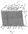
- a bulkhead 1 can be seen in perspective, which is composed of three bulkhead modules 2a, b, c. Typical Dimensions of such a module are 50 cm x 50 cm x 200 cm.
- Each Bulkhead module 2a, b, c has a bottom wall 6, a rear wall 5 and one Cover wall 7, the side bulkhead modules 2a, c also over each have a side wall 4.
- the middle bulkhead module 2b has in the ceiling wall 7, a suction opening 3, in which, for example Fan can be used, the air from the inside of the Aspirating bulkhead 1. This will contaminate the air Front wall 8 sucked into the interior of the bulkhead 1.
- a frame-like frame 22 is provided, the front wall 8 by a Filter element 9 and a front baffle 12 is formed.
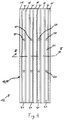
- FIG 3 shows a bulkhead 1 in which the baffle grille 12 have been omitted so that the filter elements 9 can be seen.
- the Filter elements are held in a frame 10, which by means of an above and lever lock 11 arranged at the bottom in the respective bulkhead module 2a-d is held.
- Figs. 1 and 2 is shown on the top and bottom of the Frame 22 each have a rail 18 and 19 arranged, for example a Z-shaped profile element, in particular a correspondingly shaped one Sheet metal can exist. It is possible to use these rails 18 and 19 as in the Fig. 1 can be seen to train consistently. But there is also Possibility to assign a separate rail to each module Needed to have an unimpeded lateral displacement of the baffle 12th to enable.
- the baffle 12 pushed out of the rails 18 and 19 laterally and parked next to the bulkhead 1. It is then the corresponding filter element of the relevant bulkhead module 2a-c accessible. After the exchange of this filter element in question is the adjacent baffle 12 moved so that the filter element underneath for an exchange is accessible. The individual filter elements can thus be used one after the other be replaced.
- the baffle 12 can be made just like the other components of the bulkhead modules 2a-d any materials. However, sheets are preferred for the Manufacture of the individual components used.
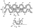
- the baffle Grating elements 13, 14 can each consist of one Single sheet are made, openings 21 are punched, the are elongated in the embodiment shown here, so that Form vertically aligned lattice fins 15 between the openings.
- the punched openings 21 are arranged so that between the Grid lamellas 15 webs 20 remain, the lattice lamellas with one another connect. It can therefore encompass one of the grating lamellae 15 Frame are dispensed with, so that the baffle 12 is lighter overall.
- each baffle grid 12 consists of two grid elements 13 and 14 exists, the grating lamellae 15 being offset from one another are, so that a corresponding air deflection by the arrows is marked, can take place before the contaminated air on the Filter elements arrives.
- Each individual lamella 15 consists, as in FIG. 5b is shown enlarged, from a slat middle section 17 and the two Slat edges 16, which with the slat middle section 17 an angle ⁇ form, which is preferably 45 °. This will improve Redirection and less adhesion of the substances in the air achieved.
Landscapes
- Filtering Of Dispersed Particles In Gases (AREA)
- Details Or Accessories Of Spraying Plant Or Apparatus (AREA)
- Joining Of Building Structures In Genera (AREA)
- Ventilation (AREA)
Abstract
Description
- Fig. 1
- eine Spritzwand, die aus drei Spritzwandmodulen zusammengesetzt ist, in perspektivischer Darstellung,
- Fig. 2
- einen Vertikalschnitt durch ein in der Fig. 1 gezeigtes Spritzwandmodul,
- Fig. 3
- eine perspektivische Darstellung einer Spritzwand ohne Prallgitter,
- Fig. 4
- die Vorderansicht eines Prallgitters und
- Fign. 5a und 5b
- einen Horizontalschnitt längs der Linie V-V des in Fig. 4 gezeigten Prallgitters einschließlich einer Detailvergrößerung.
- 1
- Spritzwand
- 2a,b,c,d
- Spritzwandmodul
- 3
- Absaugöffnung
- 4
- Seitenwand
- 5
- Rückwand
- 6
- Bodenwand
- 7
- Deckenwand
- 8
- Vorderwand
- 9
- Filterelement
- 10
- Rahmen des Filterelementes
- 11
- Hebelverschluß
- 12
- Prallgitter
- 13
- Gitterelement
- 14
- Gitterelement
- 15
- Gitterlamelle
- 16
- Lamellenrand
- 17
- Lamellenmittelabschnitt
- 18
- obere Führungsschiene
- 19
- untere Führungsschiene
- 20
- Steg
- 21
- Öffnung
- 22
- Gestell
Claims (10)
- Spritzwandmodul, gekennzeichnet durch ein ein Modulmaß aufweisendes Gestell (22) mit mindestens einer Boden-, Rück- und Deckenwand (5,6,7) und mit einer für abzusaugende Luft durchlässigen Vorderwand (8), die mindestens ein Filterelement (9) umfaßt, und durch Mittel zum Verbinden mit mindestens einem weiteren Spritzwandmodul (2a-d).
- Spritzwandmodul nach Anspruch 1, dadurch gekennzeichnet, daß vor dem Filterelement (9) ein Prallgitter (12) mit labyrinthartig angeordneten Gitterlamellen (15) angeordnet ist, wobei das Prallgitter (12) in Führungsschienen (18,19) seitlich verschiebbar gehalten ist.
- Spritzwandmodul nach Anspruch 2, dadurch gekennzeichnet, daß die Führungsschienen (18,19) an der Außenseite des Gestells (22) angeordnet sind.
- Spritzwandmodul nach Anspruch 2 oder 3, dadurch gekennzeichnet, daß die Führungsschienen (18,19) aus Z-förmigen Profilelementen bestehen.
- Spritzwandmodul nach einem der Ansprüche 2 bis 4, dadurch gekennzeichnet, daß das Prallgitter (12) aus zwei hintereinander angeordneten Gitterelementen (13,14) besteht.
- Spritzwandmodul nach Anspruch 5, dadurch gekennzeichnet, daß jedes Gitterelement (13,14) aus einer mit ausgestanzten Öffnungen (21) versehenen Platte besteht.
- Spritzwandmodul nach einem der Ansprüche 2 bis 6, dadurch gekennzeichnet, daß die Gitterlamellen (15) über Stege (20) miteinander verbunden sind.
- Spritzwandmodul nach einem der Ansprüche 2 bis 7, dadurch gekennzeichnet, daß die Ränder (16) der Gitterlamellen (15) umgebogen sind.
- Spritzwandmodul nach einem der Ansprüche 2 bis 8, dadurch gekennzeichnet, daß die Lamellenränder (16) mit den Lamellenmittelabschnitten (17) einen Winkel α mit 40° < α < 50° bilden.
- Spritzwand mit Boden-, Decken- und Seitenwänden und mit einer für abzusaugende Luft durchlässigen Vorderwand, die aus mindestens einem Filterelement besteht, gekennzeichnet durch mindestens zwei nebeneinander angeordnete Spritzwandmodule (2a-d) mit jeweils mindestens einem eigenem Filterelement (9).
Applications Claiming Priority (2)
| Application Number | Priority Date | Filing Date | Title |
|---|---|---|---|
| DE19816623A DE19816623C2 (de) | 1998-04-15 | 1998-04-15 | Spritzwandmodul und aus Spritzwandmodulen aufgebaute Spritzwand |
| DE19816623 | 1998-04-15 |
Publications (3)
| Publication Number | Publication Date |
|---|---|
| EP0950435A2 true EP0950435A2 (de) | 1999-10-20 |
| EP0950435A3 EP0950435A3 (de) | 2004-03-24 |
| EP0950435B1 EP0950435B1 (de) | 2008-10-29 |
Family
ID=7864561
Family Applications (1)
| Application Number | Title | Priority Date | Filing Date |
|---|---|---|---|
| EP99104865A Expired - Lifetime EP0950435B1 (de) | 1998-04-15 | 1999-03-11 | Spritzwandmodul und aus Spritzwandmodulen aufgebaute Spritzwand |
Country Status (4)
| Country | Link |
|---|---|
| EP (1) | EP0950435B1 (de) |
| AT (1) | ATE412471T1 (de) |
| DE (2) | DE19816623C2 (de) |
| ES (1) | ES2313761T3 (de) |
Cited By (2)
| Publication number | Priority date | Publication date | Assignee | Title |
|---|---|---|---|---|
| EP3524361A1 (de) * | 2018-02-09 | 2019-08-14 | Eisenmann SE | Vorrichtung zum abscheiden von overspray |
| CN110270460A (zh) * | 2019-06-25 | 2019-09-24 | 河北骄阳丝网设备有限责任公司 | 钢结构喷涂系统 |
Families Citing this family (2)
| Publication number | Priority date | Publication date | Assignee | Title |
|---|---|---|---|---|
| DE102006005629A1 (de) * | 2006-02-08 | 2007-08-09 | Rehau Ag + Co. | Lackieranlage im Modulaufbau |
| DE102007063162B3 (de) * | 2007-12-19 | 2009-03-05 | Karl-Heinz Fehr | Modulartig zusammengesetzte Beschichtungszelle |
Family Cites Families (5)
| Publication number | Priority date | Publication date | Assignee | Title |
|---|---|---|---|---|
| DE918193C (de) * | 1950-02-09 | 1954-09-20 | Heinrich Ausserehl | Farbspritzstand |
| CA1296885C (en) * | 1988-11-04 | 1992-03-10 | Geln F. Widdifield | Air filtering system for paint spray |
| FR2687082A1 (fr) * | 1992-02-11 | 1993-08-13 | Sitonet Sa | Tunnel de traitement de surface et son procede de realisation. |
| DE9211612U1 (de) * | 1992-08-28 | 1993-01-28 | Machholz-Industrie-Vertretungen-GmbH, 4620 Castrop-Rauxel | Einrichtung zum Anrühren und Mischen von Farben |
| US5288324A (en) * | 1992-12-18 | 1994-02-22 | Shaneyfelt Jack L | Multi-color powder coat paint recovery apparatus |
-
1998
- 1998-04-15 DE DE19816623A patent/DE19816623C2/de not_active Expired - Fee Related
-
1999
- 1999-03-11 DE DE59914886T patent/DE59914886D1/de not_active Expired - Lifetime
- 1999-03-11 AT AT99104865T patent/ATE412471T1/de not_active IP Right Cessation
- 1999-03-11 EP EP99104865A patent/EP0950435B1/de not_active Expired - Lifetime
- 1999-03-11 ES ES99104865T patent/ES2313761T3/es not_active Expired - Lifetime
Non-Patent Citations (1)
| Title |
|---|
| None |
Cited By (3)
| Publication number | Priority date | Publication date | Assignee | Title |
|---|---|---|---|---|
| EP3524361A1 (de) * | 2018-02-09 | 2019-08-14 | Eisenmann SE | Vorrichtung zum abscheiden von overspray |
| CN110270460A (zh) * | 2019-06-25 | 2019-09-24 | 河北骄阳丝网设备有限责任公司 | 钢结构喷涂系统 |
| CN110270460B (zh) * | 2019-06-25 | 2024-03-08 | 河北骄阳焊工有限公司 | 钢结构喷涂系统 |
Also Published As
| Publication number | Publication date |
|---|---|
| ATE412471T1 (de) | 2008-11-15 |
| EP0950435B1 (de) | 2008-10-29 |
| DE19816623A1 (de) | 1999-10-21 |
| DE19816623C2 (de) | 2001-05-17 |
| DE59914886D1 (de) | 2008-12-11 |
| ES2313761T3 (es) | 2009-03-01 |
| EP0950435A3 (de) | 2004-03-24 |
Similar Documents
| Publication | Publication Date | Title |
|---|---|---|
| DE202007001942U1 (de) | Tropfenabscheider für Gaswäscher | |
| DE2220638C2 (de) | Lüftungsgitter mit Jalousieleisten | |
| DE3616554C2 (de) | Messerwalzen-Abstreifvorrichtung für Aktenvernichter oder dgl. | |
| DE19816623C2 (de) | Spritzwandmodul und aus Spritzwandmodulen aufgebaute Spritzwand | |
| DE8910063U1 (de) | Induktivdurchlaß | |
| EP0438676B1 (de) | Vorrichtung zum Abscheiden von Fluiden | |
| EP0554960B1 (de) | Lüftungsgitter | |
| DE19513201C1 (de) | Tropfenabscheider für eine dezentrale Heizungs-, Lüftungs- und/oder Kühlvorrichtung | |
| DE3111360C2 (de) | Lüftungsvorrichtung für Räume mit zwei getrennten Strömungswegen zur Be- und Entlüftung | |
| EP1458455B1 (de) | Halteprofil für lamellen, modulare halteprofileinheit und eine solche aufweisende abscheide-, lichtreduzier- oder strömungsleiteinheit | |
| EP0687790B1 (de) | Linearverbinder für hohle Abstandsprofile eines Mehrscheibenisolierglases | |
| DE19715516C1 (de) | Lüftungsgitter | |
| CH659930A5 (de) | Abdeckrost fuer entmistungskanaele in viehstaellen. | |
| CH663079A5 (de) | Lueftungsvorrichtung fuer den einbau in eine fenster-, tuer- oder andere wandoeffnung eines gebaeudes. | |
| DE2802696C2 (de) | ||
| DE3231486C2 (de) | ||
| EP0667497A1 (de) | Lüftungsanordnung | |
| DE102006011152B4 (de) | Tropfenabscheideranordnung | |
| DE3801425A1 (de) | Lueftungsdecke | |
| DE4200722A1 (de) | Spritzwasserfaenger fuer das vom fahrzeugrad aufgewirbelte wasser | |
| DE2828338C2 (de) | Rechteckiger Deckenauslaß | |
| EP3669963B1 (de) | Tropfenabscheider mit neuer verbindungsstruktur | |
| DE1580939C3 (de) | Lüftungsgitter für Fahrzeuge, insbesondere für Schienenfahrzeuge | |
| EP0077440B1 (de) | Teleskopabdeckung für Werkzeugmaschinen | |
| EP0077456B1 (de) | Abdeckung für das Maschinenbett von Werkzeugmaschinen |
Legal Events
| Date | Code | Title | Description |
|---|---|---|---|
| PUAI | Public reference made under article 153(3) epc to a published international application that has entered the european phase |
Free format text: ORIGINAL CODE: 0009012 |
|
| AK | Designated contracting states |
Kind code of ref document: A2 Designated state(s): AT BE CH CY DE DK ES FI FR GB GR IE IT LI LU MC NL PT SE |
|
| AX | Request for extension of the european patent |
Free format text: AL;LT;LV;MK;RO;SI |
|
| PUAL | Search report despatched |
Free format text: ORIGINAL CODE: 0009013 |
|
| AK | Designated contracting states |
Kind code of ref document: A3 Designated state(s): AT BE CH CY DE DK ES FI FR GB GR IE IT LI LU MC NL PT SE |
|
| AX | Request for extension of the european patent |
Extension state: AL LT LV MK RO SI |
|
| 17P | Request for examination filed |
Effective date: 20040504 |
|
| AKX | Designation fees paid |
Designated state(s): AT BE CH DE ES FR GB LI |
|
| AXX | Extension fees paid |
Extension state: SI Payment date: 20040504 Extension state: RO Payment date: 20040504 Extension state: MK Payment date: 20040504 Extension state: LV Payment date: 20040504 Extension state: LT Payment date: 20040504 Extension state: AL Payment date: 20040504 |
|
| 17Q | First examination report despatched |
Effective date: 20070418 |
|
| GRAP | Despatch of communication of intention to grant a patent |
Free format text: ORIGINAL CODE: EPIDOSNIGR1 |
|
| GRAS | Grant fee paid |
Free format text: ORIGINAL CODE: EPIDOSNIGR3 |
|
| GRAA | (expected) grant |
Free format text: ORIGINAL CODE: 0009210 |
|
| AK | Designated contracting states |
Kind code of ref document: B1 Designated state(s): AT BE CH DE ES FR GB LI |
|
| AX | Request for extension of the european patent |
Extension state: AL LT LV MK RO SI |
|
| REG | Reference to a national code |
Ref country code: GB Ref legal event code: FG4D Free format text: NOT ENGLISH |
|
| REG | Reference to a national code |
Ref country code: CH Ref legal event code: EP |
|
| REF | Corresponds to: |
Ref document number: 59914886 Country of ref document: DE Date of ref document: 20081211 Kind code of ref document: P |
|
| REG | Reference to a national code |
Ref country code: ES Ref legal event code: FG2A Ref document number: 2313761 Country of ref document: ES Kind code of ref document: T3 |
|
| PLBE | No opposition filed within time limit |
Free format text: ORIGINAL CODE: 0009261 |
|
| STAA | Information on the status of an ep patent application or granted ep patent |
Free format text: STATUS: NO OPPOSITION FILED WITHIN TIME LIMIT |
|
| 26N | No opposition filed |
Effective date: 20090730 |
|
| REG | Reference to a national code |
Ref country code: CH Ref legal event code: PL |
|
| PG25 | Lapsed in a contracting state [announced via postgrant information from national office to epo] |
Ref country code: LI Free format text: LAPSE BECAUSE OF NON-PAYMENT OF DUE FEES Effective date: 20090331 Ref country code: CH Free format text: LAPSE BECAUSE OF NON-PAYMENT OF DUE FEES Effective date: 20090331 |
|
| PGFP | Annual fee paid to national office [announced via postgrant information from national office to epo] |
Ref country code: ES Payment date: 20100324 Year of fee payment: 12 |
|
| PGFP | Annual fee paid to national office [announced via postgrant information from national office to epo] |
Ref country code: FR Payment date: 20100331 Year of fee payment: 12 |
|
| PGFP | Annual fee paid to national office [announced via postgrant information from national office to epo] |
Ref country code: GB Payment date: 20100324 Year of fee payment: 12 Ref country code: AT Payment date: 20100322 Year of fee payment: 12 |
|
| PGFP | Annual fee paid to national office [announced via postgrant information from national office to epo] |
Ref country code: BE Payment date: 20100323 Year of fee payment: 12 |
|
| BERE | Be: lapsed |
Owner name: KRAUTZBERGER G.M.B.H. Effective date: 20110331 |
|
| LTLA | Lt: lapse of european patent or patent extension |
Effective date: 20110311 |
|
| GBPC | Gb: european patent ceased through non-payment of renewal fee |
Effective date: 20110311 |
|
| PG25 | Lapsed in a contracting state [announced via postgrant information from national office to epo] |
Ref country code: AT Free format text: LAPSE BECAUSE OF NON-PAYMENT OF DUE FEES Effective date: 20110311 |
|
| REG | Reference to a national code |
Ref country code: FR Ref legal event code: ST Effective date: 20111130 |
|
| PG25 | Lapsed in a contracting state [announced via postgrant information from national office to epo] |
Ref country code: BE Free format text: LAPSE BECAUSE OF NON-PAYMENT OF DUE FEES Effective date: 20110331 |
|
| REG | Reference to a national code |
Ref country code: DE Ref legal event code: R082 Ref document number: 59914886 Country of ref document: DE Representative=s name: MEHLER ACHLER PATENTANWAELTE PARTNERSCHAFT MBB, DE Ref country code: DE Ref legal event code: R082 Ref document number: 59914886 Country of ref document: DE Representative=s name: MEHLER ACHLER PATENTANWAELTE, DE |
|
| PG25 | Lapsed in a contracting state [announced via postgrant information from national office to epo] |
Ref country code: FR Free format text: LAPSE BECAUSE OF NON-PAYMENT OF DUE FEES Effective date: 20110331 |
|
| PG25 | Lapsed in a contracting state [announced via postgrant information from national office to epo] |
Ref country code: GB Free format text: LAPSE BECAUSE OF NON-PAYMENT OF DUE FEES Effective date: 20110311 |
|
| REG | Reference to a national code |
Ref country code: ES Ref legal event code: FD2A Effective date: 20120509 |
|
| PG25 | Lapsed in a contracting state [announced via postgrant information from national office to epo] |
Ref country code: ES Free format text: LAPSE BECAUSE OF NON-PAYMENT OF DUE FEES Effective date: 20110312 |
|
| REG | Reference to a national code |
Ref country code: DE Ref legal event code: R079 Ref document number: 59914886 Country of ref document: DE Free format text: PREVIOUS MAIN CLASS: B05B0015120000 Ipc: B05B0016000000 |
|
| PGFP | Annual fee paid to national office [announced via postgrant information from national office to epo] |
Ref country code: DE Payment date: 20180313 Year of fee payment: 20 |
|
| REG | Reference to a national code |
Ref country code: DE Ref legal event code: R071 Ref document number: 59914886 Country of ref document: DE |